EP0666367B1 - Kupplungskonstruktion zwischen Rollen einer Breit-Nip Presse - Google Patents
Kupplungskonstruktion zwischen Rollen einer Breit-Nip Presse Download PDFInfo
- Publication number
- EP0666367B1 EP0666367B1 EP94850073A EP94850073A EP0666367B1 EP 0666367 B1 EP0666367 B1 EP 0666367B1 EP 94850073 A EP94850073 A EP 94850073A EP 94850073 A EP94850073 A EP 94850073A EP 0666367 B1 EP0666367 B1 EP 0666367B1
- Authority
- EP
- European Patent Office
- Prior art keywords
- coupling
- tie member
- tie
- bearing housing
- extended
- Prior art date
- Legal status (The legal status is an assumption and is not a legal conclusion. Google has not performed a legal analysis and makes no representation as to the accuracy of the status listed.)
- Expired - Lifetime
Links
- 238000010276 construction Methods 0.000 title claims abstract description 43
- 238000010168 coupling process Methods 0.000 title claims abstract description 43
- 238000005859 coupling reaction Methods 0.000 title claims abstract description 43
- 230000008878 coupling Effects 0.000 title claims abstract description 42
- 229910000906 Bronze Inorganic materials 0.000 claims description 2
- ATJFFYVFTNAWJD-UHFFFAOYSA-N Tin Chemical compound [Sn] ATJFFYVFTNAWJD-UHFFFAOYSA-N 0.000 claims description 2
- 239000010974 bronze Substances 0.000 claims description 2
- KUNSUQLRTQLHQQ-UHFFFAOYSA-N copper tin Chemical compound [Cu].[Sn] KUNSUQLRTQLHQQ-UHFFFAOYSA-N 0.000 claims description 2
- 238000010438 heat treatment Methods 0.000 description 2
- XLYOFNOQVPJJNP-UHFFFAOYSA-N water Substances O XLYOFNOQVPJJNP-UHFFFAOYSA-N 0.000 description 2
- 230000001143 conditioned effect Effects 0.000 description 1
- 230000000694 effects Effects 0.000 description 1
- 239000011796 hollow space material Substances 0.000 description 1
- 230000006698 induction Effects 0.000 description 1
- 238000005461 lubrication Methods 0.000 description 1
- 238000000034 method Methods 0.000 description 1
- 238000003825 pressing Methods 0.000 description 1
Images



Classifications
-
- D—TEXTILES; PAPER
- D21—PAPER-MAKING; PRODUCTION OF CELLULOSE
- D21F—PAPER-MAKING MACHINES; METHODS OF PRODUCING PAPER THEREON
- D21F3/00—Press section of machines for making continuous webs of paper
- D21F3/02—Wet presses
- D21F3/0209—Wet presses with extended press nip
- D21F3/0218—Shoe presses
-
- D—TEXTILES; PAPER
- D21—PAPER-MAKING; PRODUCTION OF CELLULOSE
- D21F—PAPER-MAKING MACHINES; METHODS OF PRODUCING PAPER THEREON
- D21F7/00—Other details of machines for making continuous webs of paper
- D21F7/001—Wire-changing arrangements
Definitions
- the invention concerns a coupling construction between extended-nip rolls, according to the preamble of claim 1, which is based on DE-A-4219503.
- the nip between extended-nip rolls consists of a pair of rolls composed of SYM-ZL and SYM-BELT rolls.
- a special feature of such a nip is the high linear load.
- the linear load is at the maximum up to 1200 kN/m. In such a case, a normal screw coupling is not possible, because, in order to overcome the linear load, 130 screws per roll would be needed.
- tie members for joining together the bearing housings of the rolls in an extended-nip press.
- the tie members have been connected with the bearing-housing constructions so that, when the coupling is being uncoupled, they can be pivoted into such a position that the uncoupled roll / mantle belt / bearing can be removed.
- each tie member is linked with one of the bering housings.
- the tie member is fitted to pivot in relation to the bearing housing and so that the end of the tie member is fitted to be locked by means of a wedge effect with the other bearing housing.
- the moving of the tie member takes place by means of a hydraulic cylinder.
- two tie members are employed, and the coupling construction is symmetric in relation to the vertical central axis (Y axis) of the construction.
- the construction in accordance with the invention comprises an articulation point at each end of the tie member.
- Said solution of construction permits the tie member to be operated optionally so that the tie member is linked to be pivoted at either one of the bearing housings, either the upper or the lower bearing housing. In this way, it is possible to condition/replace either the upper bearing housing or the lower bearing housing or to condition/replace either the upper roll or the lower roll. For example, it is easy to replace the belt mantle by uncoupling the connection between the bearing housings.
- the ultimate fixing of the tie member to the constructions of the bearing housing is carried out by means of screw members or equivalent.
- the uncoupling of the tie member from the friction joint is carried out, in the first stage, by means of screw members or equivalent.
- the shifting of the tie member itself apart from the bearing housing in engagement with it takes place by means of a hydraulic cylinder.
- the solution in accordance with the invention is sufficiently simple and, yet, operable.
- the coupling construction does not require a large space.
- the nip forces do not have to be transferred to the frame constructions. In such a case, an expensive and spacious outside frame system is avoided.
- the solution is also well suitable for modernizations.
- the device in accordance with the invention for joining together of extended-nip press rolls is characterized that the extended-nip press rolls are joined together by their ends by means of two tie members, which tie members are placed symmetrically in relation to the vertical axis (Y axis) and which tie members can be connected optionally with either one of the bearing housings, in which case, by means of the selective coupling, either the upper bearing housing or the lower bearing housing can be removed/serviced.
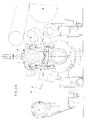
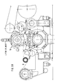
- Figure 1 is a side view of an extended-nip press equipment of a paper machine / board machine.
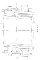
- Figure 2 shows the extended-nip press equipment as viewed in the machine direction and partly in section.
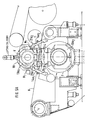
- FIG 3A shows an extended-nip press equipment in accordance with the invention with the rolls of the extended-nip press joined together by their bearing housings.
- Figure 3B shows the equipment as shown in Fig. 3A as viewed in the direction of the arrow K 1 in Fig. 3A.
- Figure 4A is an axonometric exploded view of the parts of the coupling construction between the rolls in the equipment as shown in Figs. 3A and 3B.
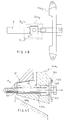
- Figure 4B illustrates the engagement of the cylinder S with the middle frame 21a 2 and with the tie member 14a 2 .
- Figure 4C illustrates the engagement of the tie member 14a 2 with the frame R 2 by means of a screw, by means of which screw the tie member 14a 2 can also be detached from the engagement with the frame part R 2 .
- Figure 5A shows an operation stage of the device in accordance with the invention in which the lower roll can be serviced.
- Figure 5B shows a stage of the method in accordance with the invention in which the upper roll can be lifted off, for example, for servicing, the coupling means remaining in connection with the bearing housings of the lower roll.
- Fig. 1 shows an extended-nip press equipment of a paper machine.
- the web W is passed into the nip N between the lower extended-nip press roll 11 and the back-up roll 10 while placed between the felt H and the roll face 10' of the back-up roll 10.
- Fig. 2 shows the rolls 10 and 11 of Fig. 1 as viewed in the machine direction.
- the extended nip between the rolls 10 and 11 is denoted in the figure with the reference arrow N.
- the felt H and the web W are passed through the nip N.
- the roll 10 is a variable-crown back-up roll
- the roll 11 is an extended-nip press roll that comprises the loading means 12a 1 ,12a 2 ..., in which roll the loading means 12a 1 , 12a 2 ..., preferably cylinder means in the central axle 13, are fitted to act with a force upon the loading or glide shoe 12b and further, through the flexible closed glide-belt mantle F, upon the web W so as to remove water from the web.
- the term web W refers to a paper or board web.
- the lower extended-nip press roll 11 comprises a flexible closed glide-belt mantle F, which is fitted to run along the face of the loading shoe, i.e. of the glide shoe 12b, an oil medium being passed into the space between the glide shoe 12b and the closed glide-belt mantle F to constitute the lubrication medium.
- the back-up roll 10 may be preferably a roll heated from inside by means of a heating medium, e.g. water, steam or oil, or from outside, e.g., by means of induction or infrared heating.
- the back-up roll 10 may also be a non-heated roll.
- Fig. 3A shows a coupling construction in accordance with the invention between the rolls in an extended-nip press.
- the first bearing housing 13a 1 which is the upper bearing housing in the figure
- the second bearing housing which is the lower bearing housing 13a 2 as shown in the figure
- the upper roll and the lower roll are interconnected by means of the tie members 14a 1 and 14a 2 .
- the bearing housings are interconnected by means of similar tie members 14a 1 and 14a 2 .
- Fig. 3B shows the coupling construction shown in Fig. 3A, viewed in the direction of the arrow K 1 in Fig. 3A.
- Fig. 4A is an axonometric exploded view of the parts of the coupling construction in an equipment in accordance with the invention.
- the fastening construction in accordance with the invention is symmetric in relation to the vertical axis (Y axis).
- the construction of the fastening construction is also substantially symmetric in relation to the second axis (X axis) perpendicular to the Y axis.
- the first bearing housing which is the upper bearing housing 13a 1 as shown in Fig. 4A, includes a lifting bracket 15.
- the lifting bracket 15 comprises a bracket part 15a 1 , and therein a through hole 15a 2 for the loop of the lifting device, and a plate part 15a 3 connected with the bracket part 15a 1 , which plate part is attached to the frame R 1 of the bearing housing 13a 1 by means of screw means 16b 1 ...16b 4 .
- the screws 16a 1 ...16a 4 are passed through the screw holes 15b 1 ...15b 4 into the frame R 1 , being threaded into the threaded holes in said frame.
- the bearing housing 13a 1 comprises a lower fastening construction B 1 .
- the fastening construction B 1 is symmetric in relation to the Y axis and comprises similar fastening-construction portions B 1.1 ,B 1.2 .
- the frame R 1 is preferably a cast construction.
- the frame R 1 comprises a central opening M for the axle of the upper roll. In the figures, the bearing means on which the rolls revolve are not shown separately.
- the frame comprises a side face C 1 and therein a plane T 1 . On the side face C, there is a side projection 16, comprising a face C 2 .
- the face planes T 1 and T 2 of the faces C 1 and C 2 are preferably parallel to one another, connected by a coupling face C 3 placed as inclined in relation to said planes.
- the side face C 1 comprises a screw hole 17a 1 and, in a corresponding way, the face C 2 comprises a screw hole 17a 2 ,17a 3 .
- the face C 1 further comprises a bracket 30a 1 ,20a 2 and therein shaft holes D 1 ,D 2 .
- the frame R 1 further comprises coupling means B 1.3 ,B 1.4 , which are similar to one another and which are placed at both sides of the Y axis.
- the coupling means B 1.3 comprise a plane face T 4 and therein a projection edge 18, which comprises screw holes 19a 1 ,19a 2 as well as a keyway 20 in the bottom face.
- the solution of equipment comprises hollow middle frames 21a 1 ,21a 2 , which are constructions similar to one another.
- the middle frame 21a 1 comprises an upper wall 22a 1 and a lower wall 22a 2 .
- the solution comprises side walls 22a 3 ,22a 4 , which interconnect the upper and the lower walls perpendicularly and which comprise holes 23a 1 ,23a 2 for the shaft of the pivot cylinder S.
- side walls 24a 1 ,24a 2 between the upper and the lower walls 22a 1 ,22a 2 .
- the side walls 24a 1 ,24a 2 comprise openings 25a 1 , 25a 2 .
- the walls mentioned above define a hollow space E in the interior space between them, the cylinder being fitted partly in said space by its cylinder frame and so that the shaft connected with the cylinder frame is connected and linked pivotally in the axle holes 23a 1 ,23a 2 .
- the upper and the lower walls 22a 1 ,22a 2 project by their ends from the side walls, and their projection portions comprise screw holes 26a 1 ...26a 4 and grooves 26a 5 ...26a 8 for the screws.
- the upper wall 22a 1 comprises a plane face T 5 and therein a keyway 27a 1 and, correspondingly, the lower wall part 22a 2 comprises a plane face T 6 and therein a keyway 27a 2 .
- the screws are not shown separately by whose means the middle frame 21a 1 , 21a 2 is connected to its bearing housings.
- the solution of equipment comprises adapter pieces 28a 1 ,28a 2 , which are construction parts similar to one another.
- the adapter piece 28a 1 comprises an upper plane face T 7 and a lower plane face T 8 and keyways 29a 1 ,29a 2 in said faces.
- the adapter piece comprises grooves 30a 1 ...30a 4 for the fitting of fastening parts, such as screws.
- the lower, second bearing housing 13a 2 comprises a frame R 2 , preferably a cast frame, and therein a central hole M 2 for the axle of the lower roll.
- the bearing housing comprises upper fastening means B 2.1 ,B 2.2 , which are constructions substantially similar to one another and which correspond to the fastening and coupling means B 1.1 ,B 1.2 of the upper bearing housing. Thus, they are constructions symmetric in relation to the central axis Y.
- said fastening means comprise a face C 1 , a second face C 2 , which has been raised in relation to said first face C 1 , and between said faces a face C 3 , which is a coupling face.
- the face C 3 is preferably an inclined face.
- the face C 4 comprises a groove 300 for a bracket, and a hole 31 in the frame R 2 , whereby it is possible to pass the shaft 32 through the hole 31 and through the hole provided in the fastening bracket of the tie member, which fastening bracket is placed in the groove 300 for the bracket.
- the fastening means B 2.3 ,B 2.4 are constructions similar to one another and similar to the fastenings B 1.3 and B 1.4 of the upper bearing housing.
- the lower bearing housing comprises lower fastening means B 1.5 and B 1.6 , which are similar to one another. They comprise a plate 33b and therein grooves 33a 1 ...33a 4 for screws, by whose means the construction is fixed to the machine foundation P.
- Each tie member 14a 1 ,14a 2 comprises a middle frame 34a 1 and, at both of its ends, side frames 34a 2 ,34a 3 , whose longitudinal axes are substantially perpendicular to the longitudinal axis Z 1 of the middle frame.
- the tie members 14a 1 , 14a 2 are symmetric in relation to the central axis X'.
- Each tie member comprises an articulation point N 1 ,N 2 at its ends, in which case the tie member can be connected optionally with either one of the bearing housings.
- At each end of the middle frame 34a 1 there is a bracket 35a 1 ,35a 2 .
- the bracket 35a 1 includes a hole 36, through which the shaft 37 can be passed, in which case the tie member can be coupled, with an articulated joint, with one of the bearing housings by means of said shaft 37.
- the other end of the tie member comprises a similar bracket construction 35a 2 , by whose means the tie member can be coupled optionally, with an articulated joint, with the other bearing housing.
- the tie member 14a 1 , 14a 2 comprises a handle, by whose means the tie member can be displaced by making use of an outside device.
- the middle frame 34a 1 of the tie member comprises a central opening 38 passing through the middle frame.
- brackets 39a 1 ,39a 2 At both sides of the opening 38, there are brackets 39a 1 ,39a 2 .
- the brackets 39a 1 ,39a 2 comprise through holes 40a 1 ,40a 2 for a shaft, whereby the pivot cylinder S can be coupled with the tie member by the end of the piston rod.
- the side frames 34a 2 ,34a 3 comprise a wedge piece 41 of tin bronze, whose coupling face D' is preferably a cylindrical face.
- the middle frame 34a 1 comprises screw holes 42a 1 ,42a 2 and 42a 3 , of which holes, tightening screws 43a 1 ,43a 2 are passed through the holes 42a 1 ,42a 2 , and of which holes, a detaching and tightening screw 43a 3 is passed through the hole 42a 3 .
- Fig. 4B is an illustration on an enlarged scale of the engagement of the tie member 14a 1 with the cylinder device S.
- the cylinder S which is preferably a hydraulic cylinder, is further coupled by its cylinder frame S' with the middle frame 21a 1 .
- the middle frames 21a 1 and 21a 2 can be coupled by separate screw means (not shown) both with the upper bearing housing 13a 1 and with the lower bearing housing 13a 2 .
- the coupling mentioned above also permits that the tie members 14a 1 ,14a 2 can be coupled operationally either with the upper bearing housing or with the lower bearing housing.
- Fig. 4C shows the engagement of the tie member 14a 2 with the frame R 2 by means of the screw 43a 3 .
- the screw 43a 3 is passed through the screw hole 42a 3 placed in the tie member 14a 2 into the threaded hole 101 in the frame R 2 .
- the screw 43a 3 comprises a flange 102.
- the tie member 14a 2 comprises a recess 105 in one of its faces, the flange 102 of the screw 43a 3 being placed in said recess.
- Fig. 5A shows a solution of equipment in accordance with the invention in an operation stage in which the tie members 14a 1 ,14a 2 are linked pivotally with the upper bearing housing and in which solution of equipment the tie members 14a 1 ,14a 2 are kept by means of the cylinder device S in a so-called open position, in which case the lower roll and the lower bearing housing can be conditioned/detached.
- Fig. 5B shows a coupling construction in accordance with the invention in a mode of operation in which the tie members 14a 1 ,14a 2 are linked pivotally with the lower bearing housing and in which said tie members are kept in a so-called open position by means of the cylinder device S.
- the tie members are brought close to the bearing housing to be coupled, and the ultimate fixing and pressing of the tie member against its back-up face takes place by means of separate screw means.
Landscapes
- Paper (AREA)
- Rolls And Other Rotary Bodies (AREA)
- Machines For Manufacturing Corrugated Board In Mechanical Paper-Making Processes (AREA)
- Forwarding And Storing Of Filamentary Material (AREA)
Claims (11)
- Kupplungskonstruktion zwischen Langspaltpressenwalzen (11, 10), wobei eine der Walzen (11) in der Langspaltpresse eine Belastungseinrichtung, vorzugsweise einen Belastungsschuh, hat, mit deren Hilfe der Riemenmantel belastet wird und der Riemenmantel in dem Pressenspalt in Richtung auf die andere der Walzen (10) gepreßt wird, und die Langspaltpressenwalze (11) und die Gegendruckwalze (10) mit Hilfe von Bindegliedern (14a1, 14a2) lösbar miteinander verbunden sind, und zwar über die Lagergehäuse der Langspaltwalzen (10, 11),
dadurch gekennzeichnet, daß
die Bindeglieder (14a1, 14a2) entweder mit dem oberen oder dem unteren der Lagergehäuse in der Langspaltpresse schwenkbar verbunden sind. - Kupplungskonstruktion nach Anspruch 1,
dadurch gekennzeichnet, daß
die an jedem Ende der Walzen befindlichen Lagergehäuse mittels zweier Bindeglieder, den Bindegliedern (14a1; 14a2), lösbar miteinander verbunden ist, wobei jedes Paar von Bindegliedern mit Hilfe ihrer Gelenkpunkte (N1 oder N2) mit demselben Lagergehäuse verbunden ist, und daß in Kupplungssituationen die Bindeglieder mit Hilfe von einem ihrer Enden mit dem anderen Lagergehäuse, das zusammenzukoppeln ist, gegen die Kupplungsfläche dieses Lagergehäuses in Kontakt gepreßt worden sind. - Kupplungskonstruktion nach einem der vorangegangenen Ansprüche,
dadurch gekennzeichnet, daß
an jedem Ende der Walzen die Bindeglieder (14a1, 14a2) mit Bezug auf die vertikale Achse (Y-Achse) symmetrisch angeordnet sind. - Kupplungskonstruktion nach einem der vorangegangenen Ansprüche,
dadurch gekennzeichnet, daß
ein separater Schwenkzylinder (S) vorhanden ist, der mit Hilfe eines Endes mit einem zwischen den Lagergehäusen befindlichen Mittelrahmen und mit Hilfe des anderen Endes mit dem Bindeglied (14a1, 14a2) gekuppelt ist. - Kupplungskonstruktion nach dem vorangegangenen Anspruch,
dadurch gekennzeichnet, daß
ein Mittelrahmen (21a1, 21a2) vorhanden ist, der einen hohlen inwendigen Raum (E) aufweist, wobei der Schwenkzylinder (S) mit einem Ende mit Hilfe einer Gelenkverbindung mit dem Mittelrahmen verbunden ist, während der Schwenkzylinder (S) zumindest teilweise in dem hohlen inwendigen Raum (E) in dem Mittelrahmen angeordnet ist. - Kupplungskonstruktion nach einem der vorangegangenen Ansprüche,
dadurch gekennzeichnet, daß
jedes Bindeglied (14a1, 14a2) eine symmetrische Achse (X'-Achse) aufweist, und daß entsprechend das Bindeglied (14a1, 14a2) an jedem Ende des Mittelrahmens (34a1) des Bindeglieds (14a1, 14a2) Gelenkpunkte (N1, N2) aufweist. - Kupplungskonstruktion nach dem vorangegangenen Anspruch,
dadurch gekennzeichnet, daß
ein Träger (35a1, 35a2) oder dergleichen vorhanden ist, durch den die Welle (37) verlegbar ist, um das Bindeglied (14a1, 14a2) mit Hilfe einer Gelenkverbindung mit dem Lagergehäuse (13a1 oder 13a2) zu verbinden. - Kupplungskonstruktion nach einem der vorangegangenen Ansprüche,
dadurch gekennzeichnet, daß
das Bindeglied (14a1, 14a2) einen Mittelrahmen (34a1) und an beiden Enden des Mittelrahmens Seitenrahmen (34a2, 34a3) aufweist, deren Längsachsen im wesentlichen senkrecht zu der Längsachse (Z1) des Mittelrahmens sind, wobei die Seitenrahmen an den Innenflächen des somit gebildeten U-Abschnitts ein Kupplungsstück (41), vorzugsweise ein Kupplungsstück aus Zinnbronze, aufweisen, dessen Kupplungsfläche (D') mit der an der Seitenfläche des Lagergehäuses vorgesehenen Gegenkupplungsfläche (C3) in Kontakt verkeilbar ist. - Kupplungskonstruktion nach einem der vorangegangenen Ansprüche,
dadurch gekennzeichnet, daß
jedes Bindeglied (14a1, 14a2) Schraubenlöcher (42a1, 42a2, 42a3) aufweist, von welchen Löchern durch die Löcher (42a1, 42a2) Befestigungsschrauben (43a1, 43a2) verlegt worden sind, und von welchen Löchern durch das Loch (42a3) eine Ablöse- und Befestigungsschraube (43a3) verlegt worden ist, in welchem Falle das Bindeglied mit Hilfe der Schrauben mit dem Lagergehäuse lösbar kuppelbar ist, wobei ein Satz von Schrauben als Befestigungsschrauben wirkt, und zumindest eine solche Schraube vorgesehen ist, um als eine Ablöseschraube zu wirken. - Kupplungskonstruktion nach einem der vorangegangenen Ansprüche,
dadurch gekennzeichnet, daß
der Zylinder (S) ein Hydraulikzylinder ist, mit dessen Hilfe das Bindeglied (14a1, 14a2) von dem Lagergehäuse weggebracht wird, das mit diesem Bindeglied gekuppelt gewesen ist, und mit dessen Hilfe das Bindeglied (14a1, 14a2) in Verbindung mit dem mit dem Bindeglied zu kuppelnden Lagergehäuse gebracht wird. - Kupplungskonstruktion nach einem der vorangegangenen Ansprüche,
dadurch gekennzeichnet, daß
das Bindeglied (14a1, 14a2) eine Durchgangsöffnung (38) und in Verbindung mit der Öffnung eine Kupplungseinrichtung aufweist, mit deren Hilfe der Zylinder (S) mit dem Bindeglied (14a1, 14a2) kuppelbar ist.
Applications Claiming Priority (2)
| Application Number | Priority Date | Filing Date | Title |
|---|---|---|---|
| FI940522A FI101633B (fi) | 1994-02-04 | 1994-02-04 | Pitkänippitelojen välinen kytkentärakenne ja menetelmä pitkänippiteloj en yhteenliittämisessä |
| FI940522 | 1994-02-04 |
Publications (2)
| Publication Number | Publication Date |
|---|---|
| EP0666367A1 EP0666367A1 (de) | 1995-08-09 |
| EP0666367B1 true EP0666367B1 (de) | 1998-11-25 |
Family
ID=8539927
Family Applications (1)
| Application Number | Title | Priority Date | Filing Date |
|---|---|---|---|
| EP94850073A Expired - Lifetime EP0666367B1 (de) | 1994-02-04 | 1994-04-29 | Kupplungskonstruktion zwischen Rollen einer Breit-Nip Presse |
Country Status (7)
| Country | Link |
|---|---|
| US (1) | US5507223A (de) |
| EP (1) | EP0666367B1 (de) |
| JP (1) | JPH07216775A (de) |
| AT (1) | ATE173775T1 (de) |
| CA (1) | CA2123723C (de) |
| DE (1) | DE69414819T2 (de) |
| FI (1) | FI101633B (de) |
Families Citing this family (19)
| Publication number | Priority date | Publication date | Assignee | Title |
|---|---|---|---|---|
| DE4417760C2 (de) * | 1994-05-20 | 1999-03-25 | Voith Sulzer Papiermasch Gmbh | Preßvorrichtung |
| FI950580A7 (fi) * | 1995-02-10 | 1996-08-11 | Valmet Corp | Laitteisto pitkän nipin muodostavien telojen yhteenkytkennässä |
| US5788997A (en) * | 1995-06-16 | 1998-08-04 | Interko, Inc. | Stress-free multiroller dough sheeting system |
| SE504847C2 (sv) * | 1995-09-27 | 1997-05-12 | Valmet Karlstad Ab | Lyftanordning för en toppvals för en valspress i en pappers- eller kartongmaskin |
| FI107463B (fi) * | 1996-06-05 | 2001-08-15 | Metso Paper Inc | Pitkänippitelan ja sen vastatelan välinen kytkentärakenne |
| DE19713285A1 (de) * | 1997-03-29 | 1998-10-01 | Voith Sulzer Papiermasch Gmbh | Preßvorrichtung für eine Papiermaschine |
| DE19741425B4 (de) * | 1997-09-19 | 2007-04-19 | Voith Patent Gmbh | Walzenpresse |
| US6248210B1 (en) | 1998-11-13 | 2001-06-19 | Fort James Corporation | Method for maximizing water removal in a press nip |
| US7024990B1 (en) | 1999-10-13 | 2006-04-11 | Metso Paper, Inc. | Calender and an arrangement for fastening rolls of a calender |
| FI116414B (fi) * | 2001-07-05 | 2005-11-15 | Vaahto Oy | Kytkentärakenne ja menetelmä pitkänippipuristimen telojen yhteenliittämiseksi ja lukitsemiseksi |
| AT412097B (de) * | 2002-10-17 | 2004-09-27 | Andritz Ag Maschf | Pressvorrichtung |
| DE10249948A1 (de) * | 2002-10-26 | 2004-05-13 | Voith Paper Patent Gmbh | Walzenanordnung |
| DE102004028480A1 (de) * | 2004-06-11 | 2006-01-05 | Eduard Küsters Maschinenfabrik GmbH & Co. KG | Vorrichtung zum Bilden eines Langspalts |
| DE102005040722A1 (de) * | 2005-08-27 | 2007-03-01 | Voith Patent Gmbh | Pressanordnung |
| DE102007005395A1 (de) * | 2007-02-03 | 2008-08-07 | Voith Patent Gmbh | Pressanordnung |
| FI124735B (fi) * | 2010-11-26 | 2014-12-31 | Valmet Technologies Inc | Liitosjärjestely |
| DE202013101056U1 (de) * | 2012-03-16 | 2013-03-18 | Metso Paper, Inc. | Verbindungsanordnung zwischen Lagergehäusen von Walzen einer Faserbahnmaschine |
| CN103072273B (zh) * | 2012-12-24 | 2015-03-25 | 杭州珂瑞特机械制造有限公司 | 多层夹筋无纺布全能焊接设备连杆夹紧机构及压紧方法 |
| CN103395203B (zh) * | 2013-08-09 | 2016-01-20 | 衡阳新华华致橡塑制品有限公司 | 密封条在线贴绒方法及装置 |
Family Cites Families (12)
| Publication number | Priority date | Publication date | Assignee | Title |
|---|---|---|---|---|
| US2277313A (en) * | 1940-08-01 | 1942-03-24 | Goodrich Co B F | Change-roll calender |
| US2512648A (en) * | 1945-05-05 | 1950-06-27 | Beloit Iron Works | Press roll assembly |
| US3049074A (en) * | 1959-04-20 | 1962-08-14 | Fulton Iron Works Co | Mill housing |
| DE1961110A1 (de) * | 1969-12-05 | 1971-06-24 | Demag Ag | Walzwerk mit einem mehrteiligen Walzenstaender |
| DE2221785C2 (de) * | 1972-05-04 | 1984-06-14 | Horst 7101 Obergruppenbach Liebert | Walzenpresse zum Kompaktieren, Pelletieren oder Brikettieren |
| CH560852A5 (de) * | 1973-02-08 | 1975-04-15 | Escher Wyss Ag | |
| DE2606842C3 (de) * | 1976-02-20 | 1978-08-17 | Schloemann-Siemag Ag, 4000 Duesseldorf | Walzenständer in geteilter Bauart mit abnehmbaren Ständerkappen und Zugankerverbindungen zwischen dem Ständer und den Ständerkappen |
| FI833133L (fi) * | 1982-09-30 | 1984-03-31 | Beloit Corp | Press med foerlaengt nyp |
| US4790908A (en) * | 1988-02-19 | 1988-12-13 | Beloit Corporation | Extended nip press belt guide and method |
| DE9103795U1 (de) * | 1991-03-28 | 1992-04-23 | J.M. Voith Gmbh, 7920 Heidenheim | Walzenpresse |
| DE4140879A1 (de) * | 1991-12-11 | 1993-06-17 | Voith Gmbh J M | Pressenpartie |
| DE4219503C2 (de) * | 1992-06-13 | 1995-06-14 | Escher Wyss Gmbh | Walzenpresse |
-
1994
- 1994-02-04 FI FI940522A patent/FI101633B/fi not_active IP Right Cessation
- 1994-04-29 DE DE69414819T patent/DE69414819T2/de not_active Expired - Fee Related
- 1994-04-29 AT AT94850073T patent/ATE173775T1/de not_active IP Right Cessation
- 1994-04-29 EP EP94850073A patent/EP0666367B1/de not_active Expired - Lifetime
- 1994-05-13 US US08/242,440 patent/US5507223A/en not_active Expired - Fee Related
- 1994-05-17 CA CA002123723A patent/CA2123723C/en not_active Expired - Fee Related
- 1994-05-18 JP JP6127063A patent/JPH07216775A/ja active Pending
Also Published As
| Publication number | Publication date |
|---|---|
| FI101633B1 (fi) | 1998-07-31 |
| DE69414819D1 (de) | 1999-01-07 |
| EP0666367A1 (de) | 1995-08-09 |
| DE69414819T2 (de) | 1999-05-12 |
| ATE173775T1 (de) | 1998-12-15 |
| CA2123723C (en) | 1999-02-23 |
| FI940522L (fi) | 1995-08-05 |
| FI101633B (fi) | 1998-07-31 |
| FI940522A0 (fi) | 1994-02-04 |
| JPH07216775A (ja) | 1995-08-15 |
| US5507223A (en) | 1996-04-16 |
| CA2123723A1 (en) | 1995-08-05 |
Similar Documents
| Publication | Publication Date | Title |
|---|---|---|
| US5507223A (en) | Arrangement for coupling extended-nip rolls | |
| EP0619399B1 (de) | Verfahren und Vorrichtung zur Öffnung des Press-Spaltes in einer Langspaltpresse | |
| US5975532A (en) | Seal construction for a suction roll in a paper machine | |
| US5413036A (en) | Roll press, specifically for the paper industry | |
| US5693186A (en) | Method and apparatus for interconnecting rolls in an extended-nip press | |
| KR100228925B1 (ko) | 제지기계에서 이퀄라이징 프레스가 장치된 프레스부 및 프레스 방법 | |
| FI112264B (fi) | Puristinlaite | |
| US5395172A (en) | Bearing assembly | |
| DE68924559D1 (de) | Presspartie mit Gestellaufbau für eine Papiermaschine. | |
| JPH07151137A (ja) | 片持支持可能ローラ | |
| CA2124473C (en) | Apparatus for dewatering mixtures of fibrous and liquid materials | |
| JPS5966594A (ja) | 広幅ニツププレス | |
| US4551205A (en) | Press section without press suction rollers in a paper machine | |
| US5850785A (en) | Coupling construction between an extended-nip roll and a backup roll | |
| CN102535226B (zh) | 连接装置 | |
| US4879002A (en) | Frame construction of the press section in a paper machine | |
| EP0319502B1 (de) | Vorrichtung in einem freitragenden Rahmenteil der Presspartie und/oder Siebpartie einer Papiermaschine | |
| FI82089C (fi) | Presspartiet i en pappersmaskin och dess stomkonstruktion. | |
| US5577441A (en) | Pressing device for extracting liquid from a pulp web | |
| US7024990B1 (en) | Calender and an arrangement for fastening rolls of a calender | |
| EP0308028B1 (de) | Pressenpartie in einer Papiermaschine | |
| FI953702A7 (fi) | Laakeripesien välinen kytkentärakenne pitkänippipuristimessa | |
| JPH1025687A (ja) | ローラプレス | |
| FI94651B (fi) | Pitkänippipuristintelojen välinen kytkentärakenne | |
| CA2043002C (en) | Method and device in a compact press section of a paper machine for replacement of rolls and fabrics |
Legal Events
| Date | Code | Title | Description |
|---|---|---|---|
| PUAI | Public reference made under article 153(3) epc to a published international application that has entered the european phase |
Free format text: ORIGINAL CODE: 0009012 |
|
| AK | Designated contracting states |
Kind code of ref document: A1 Designated state(s): AT CH DE FR GB IT LI SE |
|
| 17P | Request for examination filed |
Effective date: 19950919 |
|
| 17Q | First examination report despatched |
Effective date: 19961216 |
|
| GRAG | Despatch of communication of intention to grant |
Free format text: ORIGINAL CODE: EPIDOS AGRA |
|
| RAP1 | Party data changed (applicant data changed or rights of an application transferred) |
Owner name: VALMET CORPORATION |
|
| GRAG | Despatch of communication of intention to grant |
Free format text: ORIGINAL CODE: EPIDOS AGRA |
|
| GRAH | Despatch of communication of intention to grant a patent |
Free format text: ORIGINAL CODE: EPIDOS IGRA |
|
| GRAH | Despatch of communication of intention to grant a patent |
Free format text: ORIGINAL CODE: EPIDOS IGRA |
|
| GRAA | (expected) grant |
Free format text: ORIGINAL CODE: 0009210 |
|
| AK | Designated contracting states |
Kind code of ref document: B1 Designated state(s): AT CH DE FR GB IT LI SE |
|
| REF | Corresponds to: |
Ref document number: 173775 Country of ref document: AT Date of ref document: 19981215 Kind code of ref document: T |
|
| REG | Reference to a national code |
Ref country code: CH Ref legal event code: NV Representative=s name: R. A. EGLI & CO. PATENTANWAELTE Ref country code: CH Ref legal event code: EP |
|
| REF | Corresponds to: |
Ref document number: 69414819 Country of ref document: DE Date of ref document: 19990107 |
|
| ITF | It: translation for a ep patent filed | ||
| ET | Fr: translation filed | ||
| PLBE | No opposition filed within time limit |
Free format text: ORIGINAL CODE: 0009261 |
|
| STAA | Information on the status of an ep patent application or granted ep patent |
Free format text: STATUS: NO OPPOSITION FILED WITHIN TIME LIMIT |
|
| 26N | No opposition filed | ||
| REG | Reference to a national code |
Ref country code: GB Ref legal event code: IF02 |
|
| PGFP | Annual fee paid to national office [announced via postgrant information from national office to epo] |
Ref country code: GB Payment date: 20040331 Year of fee payment: 11 |
|
| PGFP | Annual fee paid to national office [announced via postgrant information from national office to epo] |
Ref country code: SE Payment date: 20040402 Year of fee payment: 11 Ref country code: CH Payment date: 20040402 Year of fee payment: 11 |
|
| PGFP | Annual fee paid to national office [announced via postgrant information from national office to epo] |
Ref country code: AT Payment date: 20040405 Year of fee payment: 11 |
|
| PGFP | Annual fee paid to national office [announced via postgrant information from national office to epo] |
Ref country code: DE Payment date: 20040408 Year of fee payment: 11 |
|
| PGFP | Annual fee paid to national office [announced via postgrant information from national office to epo] |
Ref country code: FR Payment date: 20040415 Year of fee payment: 11 |
|
| PG25 | Lapsed in a contracting state [announced via postgrant information from national office to epo] |
Ref country code: IT Free format text: LAPSE BECAUSE OF NON-PAYMENT OF DUE FEES;WARNING: LAPSES OF ITALIAN PATENTS WITH EFFECTIVE DATE BEFORE 2007 MAY HAVE OCCURRED AT ANY TIME BEFORE 2007. THE CORRECT EFFECTIVE DATE MAY BE DIFFERENT FROM THE ONE RECORDED. Effective date: 20050429 Ref country code: GB Free format text: LAPSE BECAUSE OF NON-PAYMENT OF DUE FEES Effective date: 20050429 Ref country code: AT Free format text: LAPSE BECAUSE OF NON-PAYMENT OF DUE FEES Effective date: 20050429 |
|
| PG25 | Lapsed in a contracting state [announced via postgrant information from national office to epo] |
Ref country code: SE Free format text: LAPSE BECAUSE OF NON-PAYMENT OF DUE FEES Effective date: 20050430 Ref country code: LI Free format text: LAPSE BECAUSE OF NON-PAYMENT OF DUE FEES Effective date: 20050430 Ref country code: CH Free format text: LAPSE BECAUSE OF NON-PAYMENT OF DUE FEES Effective date: 20050430 |
|
| PG25 | Lapsed in a contracting state [announced via postgrant information from national office to epo] |
Ref country code: DE Free format text: LAPSE BECAUSE OF NON-PAYMENT OF DUE FEES Effective date: 20051101 |
|
| EUG | Se: european patent has lapsed | ||
| REG | Reference to a national code |
Ref country code: CH Ref legal event code: PL |
|
| GBPC | Gb: european patent ceased through non-payment of renewal fee |
Effective date: 20050429 |
|
| PG25 | Lapsed in a contracting state [announced via postgrant information from national office to epo] |
Ref country code: FR Free format text: LAPSE BECAUSE OF NON-PAYMENT OF DUE FEES Effective date: 20051230 |
|
| REG | Reference to a national code |
Ref country code: FR Ref legal event code: ST Effective date: 20051230 |