EP0668794B1 - Dispositif permettant de recouvrir des particules solides - Google Patents
Dispositif permettant de recouvrir des particules solides Download PDFInfo
- Publication number
- EP0668794B1 EP0668794B1 EP94924850A EP94924850A EP0668794B1 EP 0668794 B1 EP0668794 B1 EP 0668794B1 EP 94924850 A EP94924850 A EP 94924850A EP 94924850 A EP94924850 A EP 94924850A EP 0668794 B1 EP0668794 B1 EP 0668794B1
- Authority
- EP
- European Patent Office
- Prior art keywords
- disc
- housing
- locking pin
- parts
- disc parts
- Prior art date
- Legal status (The legal status is an assumption and is not a legal conclusion. Google has not performed a legal analysis and makes no representation as to the accuracy of the status listed.)
- Expired - Lifetime
Links
- 239000002245 particle Substances 0.000 title claims abstract description 15
- 239000007787 solid Substances 0.000 title claims abstract description 14
- 239000011248 coating agent Substances 0.000 title claims abstract description 11
- 238000000576 coating method Methods 0.000 title claims abstract description 11
- 239000007791 liquid phase Substances 0.000 claims description 3
- 239000012071 phase Substances 0.000 claims description 2
- 238000006073 displacement reaction Methods 0.000 claims 1
- 239000012530 fluid Substances 0.000 claims 1
- 239000000155 melt Substances 0.000 abstract description 7
- 239000000463 material Substances 0.000 abstract 2
- 239000007788 liquid Substances 0.000 description 6
- 238000010438 heat treatment Methods 0.000 description 4
- 238000003780 insertion Methods 0.000 description 2
- 230000037431 insertion Effects 0.000 description 2
- 238000000034 method Methods 0.000 description 2
- 238000006243 chemical reaction Methods 0.000 description 1
- 239000011247 coating layer Substances 0.000 description 1
- 239000010410 layer Substances 0.000 description 1
- 238000012261 overproduction Methods 0.000 description 1
- 125000006850 spacer group Chemical group 0.000 description 1
- 238000009827 uniform distribution Methods 0.000 description 1
Images

Classifications
-
- B—PERFORMING OPERATIONS; TRANSPORTING
- B01—PHYSICAL OR CHEMICAL PROCESSES OR APPARATUS IN GENERAL
- B01F—MIXING, e.g. DISSOLVING, EMULSIFYING OR DISPERSING
- B01F25/00—Flow mixers; Mixers for falling materials, e.g. solid particles
- B01F25/70—Spray-mixers, e.g. for mixing intersecting sheets of material
- B01F25/74—Spray-mixers, e.g. for mixing intersecting sheets of material with rotating parts, e.g. discs
-
- B—PERFORMING OPERATIONS; TRANSPORTING
- B01—PHYSICAL OR CHEMICAL PROCESSES OR APPARATUS IN GENERAL
- B01F—MIXING, e.g. DISSOLVING, EMULSIFYING OR DISPERSING
- B01F25/00—Flow mixers; Mixers for falling materials, e.g. solid particles
- B01F25/70—Spray-mixers, e.g. for mixing intersecting sheets of material
- B01F25/74—Spray-mixers, e.g. for mixing intersecting sheets of material with rotating parts, e.g. discs
- B01F25/743—Spray-mixers, e.g. for mixing intersecting sheets of material with rotating parts, e.g. discs the material being fed on both sides of a part rotating about a vertical axis
Definitions
- the invention relates to a device for coating solid-state particles with a layer obtained and solidifying from a liquid phase, in which a rotating turbine in a housing, constructed from two disk parts is provided, on a surface of a disk part with the solid particles and in an underlying cavity is supplied with the liquid forming the liquid phase, the liquid for coating the solid particles passing through an annular gap between the disk parts into an annular space leading to the outwardly thrown solid particles in the housing.
- Such a device is known from EP 0 048 312 A1.
- the two disk parts forming the turbine lie axially against one another with blade webs, which protrude downward into the cavity from the upper disk part and form flow channels between them for the liquid, which is generally formed from a melt, which then reaches the annular gap. If the amount of melt discharged which forms the liquid is to be varied, for example by different droplet sizes in the coating veil, then it becomes necessary to remove the turbine and replace it with a turbine provided with a different annular gap, or to provide spacers which change the distance between the disk parts. In both cases it is necessary to remove the turbine from the housing.
- the invention has for its object to provide a device of the type mentioned in such a way that a change in the annular gap height is possible without removing the turbine.
- a device of the type mentioned at the outset to arrange the two disk parts so as to be axially adjustable relative to one another from outside to adjust the size of the annular gap.
- this can be done in a particularly simple and advantageous manner in that the axial adjustment takes place through a central thread connecting the two disk parts, in particular a fine thread, and in that means that can be actuated from outside the housing to rotate the disk parts against one another and Means for fixing the mutual position of the disk parts are provided.
- a mutual rotation of the two disk parts which can be brought about from the outside, is sufficient in order to be able to carry out the change in the annular gap, which is generally only slight.
- the means for rotation are formed from an adjusting pin which engages radially into a first disk part through a housing slot which extends over part of the circumference, and the second disk part is advantageously provided with an anti-rotation device for this purpose.
- the turbine therefore only needs to be stopped, after which - after removal of a locking device - the two disk parts are rotated relative to one another by a certain angle, so that they can be adjusted axially against one another in the desired manner by the fine thread.
- the anti-rotation device consists of a locking pin which is guided through a housing cover and is supported on the surface of the second disk part.
- the means for fixing the relative position of the two disc parts can be formed from a locking pin which engages radially in both disc parts.
- the locking pin can be screwed into a thread provided radially in the second disk part, and the adjusting pin can be axially and non-rotatably connected to the locking pin.
- the locking pin can initially be moved out of its locking position via the adjusting pin introduced from the outside for the adjustment process. The desired adjustment can then be made when the anti-rotation device is attached to the second disk part. The locking pin is then screwed in again and the turbine can take over production again without the need for expansion or laborious conversion work.
- the two disk parts can be axially displaced relative to one another, but a feed connection for the melt protrudes expediently into the cavity in the turbine, which causes a uniform distribution of the liquid and which is firmly connected to a feed pipe coming from the outside, it is in a further development of the invention, it is advantageous if this feed connector is arranged axially displaceably in a central collar of the second disk part. Finally, a labyrinth seal can be provided between the collar and the supply nozzle, so that even with the given adjustment possibility for the annular gap, the supply for the melt forming the liquid can take place in a proven manner.
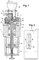
- FIG. 1 shows a device for coating solid particles, which essentially consists of a tubular housing (1) which, in the exemplary embodiment, is composed of four housing rings (1a, 1b, 1c and 1d).
- a drive shaft (4) designed as a hollow shaft for a turbine (5) is mounted, which in a manner not shown via a drive in Rotation is set.
- a further pipe (6) is laid at a distance from the inner diameter of the hollow shaft (4), which is attached to the turbine and serves to supply the trubin body with a heating medium which can pass through the channels arranged in the turbine body in the circuit .
- the turbine (5) is constructed from two disc parts (5a and 5b), the disc part (5b) being connected to the hollow shaft (4) and the tube (6) and also having the heating channels (7).
- the disc part (5b) is provided with a threaded connector (8) which has a fine thread.
- a second disk part (5a) is screwed on its surface with the Radially extending blades (10) shown in section and provided with a cavity (11) in its interior, can be guided via a fit relative to the first disc part and connected via a feed nozzle (12) to a feed tube (13), the in Fig.
- the feed connector (12) is guided in an axially displaceable manner in a collar (32) which is provided in the middle of the disk part (5a) and projects upwards.
- a labyrinth seal is provided between the feed connector (12) and the collar (32).
- the tube (13) is surrounded by a heating jacket (14) through which a heating medium can be supplied in the direction of the arrow (15) and can be discharged again through a second tube (16).
- a cylindrical tube (17) with a funnel (18) is inserted centrally in the cover (3), which is formed in two parts, through which the solid particles to be coated are supplied to the surface of the disk part (5a) in a manner not shown.
- the mass required for coating is fed in the form of a melt in the heated state in the direction of the arrow (20) through the pipe (13) into the space (11) and from there via radially running bores into an annular gap (21) and from there together with the solid particles thrown radially outwards from the blades (10) into an annular space (22), in which the melt which forms a kind of veil after emerging from the annular gap (21) coats the solid particles.
- This coating layer is then cooled and solidified.
- the slot (26) opens out into a larger recess (27), which serves for better accessibility.
- the cover (3) is provided with a bore (28) which is directed obliquely from above onto the disc part (5a) in such a way that a locking pin (29) is inserted from above can be inserted at the bottom into the space between the radially extending blades (10).
- This locking pin (29) blocks rotation of the disk part (5a). If the adjusting pin (25) is pivoted counterclockwise from its position shown in FIG. 3 within its slot (26), the disk part (5b) rotates relative to the fixed disk part (5a). The disc part (5a) is therefore adjusted in its axial position relative to the disc part (5b) by the thread of the connecting piece (8) which engages in it, which is a fine thread.
- the adjustment pin is of course in a position in which it does not engage in the disk part (5a). This means that the height of the annular gap (21) also changes. If the desired height of the annular gap is set, the adjusting pin (25) is pulled out of its bore (24) and replaced by a further locking pin (30), which is shown in FIGS. 1 and 2.
- This locking pin has a threaded head and can be screwed into a corresponding thread in the bore (24). During this screwing operation, its end engages in blind hole bores (40) with an insertion cone which are radially arranged on the outer circumference of the disk part (5a) and which are evenly distributed over the circumference of the disk part (5a) at certain angular intervals. This results in securing the two disc parts (5a and 5b) to one another.
- annular gap (21) is to be adjusted after a certain operating phase, then the locking pin (30) is turned off its openings of the disc part (5a) and after the insertion of the adjustment pin (25), a new adjustment process can be carried out without the need to remove the turbine (5).
- the locking pin (30) has, for example, a hexagon socket on its end provided with the threaded head (31) for inserting the adjusting pin (25). Adjusting pin and locking pin form a common adjusting pin when the locking pin (30) is removed from its locking position by actuation by the adjusting pin. In this embodiment, it is not necessary to remove the locking pin (31) completely from the disk body (5b) each time. However, this configuration presupposes that the axial path, which is necessary for removing the locking pin (30) from the bores of the disk part (5a), is available for the head (31) of the locking pin (30) within the disk part (5b).
Landscapes
- Chemical & Material Sciences (AREA)
- Chemical Kinetics & Catalysis (AREA)
- Turbine Rotor Nozzle Sealing (AREA)
- Glanulating (AREA)
- Glass Compositions (AREA)
- Nozzles (AREA)
- Other Surface Treatments For Metallic Materials (AREA)
- Application Of Or Painting With Fluid Materials (AREA)
- Coating Apparatus (AREA)
- Manufacturing Of Micro-Capsules (AREA)
- Paints Or Removers (AREA)
Claims (10)
- Dispositif permettant de recouvrir des particules solides à l'aide d'une couche tirée d'une phase liquide et se durcissant, dans lequel est prévue une turbine (5) tournant dans un bâti, constituée de deux parties en forme de disque (5a, 5b), qui est approvisionnée en particules solides sur une surface d'une partie en forme de disque (5a) et en matière fondue formant la phase liquide dans une cavité (11) se trouvant au-dessous, la matière liquide destinée à recouvrir les particules solides parvenant dans le bâti à un espace annulaire (22) portant les particules solides projetées par la force centrifuge vers l'extérieur à travers une fente annulaire (21) entre les parties en forme de disque (5a, 5b), caractérisé en ce que les deux parties en forme de disque (5a, 5b) sont configurées axialement mobiles l'une par rapport à l'autre depuis l'extérieur pour le réglage de la hauteur de la fente annulaire (21).
- Dispositif selon la revendication 1, caractérisé en ce que le déplacement axial est obtenu grâce à un filetage central (8), notamment un filetage à pas fin, liant les deux parties en forme de disque (5a, 5b) et en ce qu'il est prévu des moyens (25) susceptibles d'être manoeuvrés depuis l'extérieur du bâti (1, 1a) permettant la rotation mutuelle des parties en forme de disque et des moyens (30) permettant la fixation de la position mutuelle des parties en forme de disque.
- Dispositif selon la revendication 2, caractérisé en ce que les moyens (25) permettant la rotation sont formés d'une broche de déplacement s'enclenchant radialement dans une première partie en forme de disque (5b) par une fente de bâti (26) s'étendant sur une partie de la périphérie.
- Dispositif selon l'une quelconque des revendications 1 à 3, caractérisé en ce que la deuxième partie en forme de disque (5a) est munie d'un dispositif de protection contre la rotation (29)
- Dispositif selon la revendication 4, caractérisé en ce que le dispositif de protection contre la rotation est formé d'une broche d'arrêt (29) dirigée à travers un couvercle de bâti (3), s'appuyant à la surface de la deuxième partie en forme de disque (5a).
- Dispositif selon la revendication 2, caractérisé en ce que les moyens permettant la fixation de la position relative des deux parties en forme de disque (5a, 5b) sont constitués d'une broche d'arrêt (24) s'enclenchant radialement dans les deux parties en forme de disque.
- Dispositif selon la revendication 6, caractérisé en ce que la broche d'arrêt (24) est susceptible d'être vissée sur un filetage prévu dans la première partie en forme de disque (5b).
- Dispositif selon la revendication 7, caractérisé en ce que la broche de déplacement (25) est susceptible d'être connectée de manière axiale et libre en rotation à la broche d'arrêt (30).
- Dispositif selon la revendication 7, caractérisé en ce qu'un embout d'approvisionnement (12) relié à un tuyau d'approvisionnement (13) de la matière fondue fixe est disposé de manière axialement mobile dans une collerette centrale (32) de la deuxième partie en forme de disque (5a).
- Dispositif selon la revendication 9, caractérisé en ce qu'entre la collerette (32) et l'embout d'approvisionnement (12) est prévue une garniture à labyrinthe.
Applications Claiming Priority (3)
| Application Number | Priority Date | Filing Date | Title |
|---|---|---|---|
| DE4330632 | 1993-09-10 | ||
| DE4330632A DE4330632C1 (de) | 1993-09-10 | 1993-09-10 | Vorrichtung zum Überziehen von Festkörperpartikeln |
| PCT/EP1994/002608 WO1995007135A1 (fr) | 1993-09-10 | 1994-08-05 | Dispositif permettant de recouvrir des particules solides |
Publications (2)
| Publication Number | Publication Date |
|---|---|
| EP0668794A1 EP0668794A1 (fr) | 1995-08-30 |
| EP0668794B1 true EP0668794B1 (fr) | 1996-11-06 |
Family
ID=6497308
Family Applications (1)
| Application Number | Title | Priority Date | Filing Date |
|---|---|---|---|
| EP94924850A Expired - Lifetime EP0668794B1 (fr) | 1993-09-10 | 1994-08-05 | Dispositif permettant de recouvrir des particules solides |
Country Status (11)
| Country | Link |
|---|---|
| US (1) | US5593500A (fr) |
| EP (1) | EP0668794B1 (fr) |
| JP (1) | JPH08501729A (fr) |
| KR (1) | KR950704031A (fr) |
| CN (1) | CN1114496A (fr) |
| AT (1) | ATE144914T1 (fr) |
| AU (1) | AU665914B2 (fr) |
| CA (1) | CA2147131A1 (fr) |
| DE (2) | DE4330632C1 (fr) |
| GR (1) | GR3021597T3 (fr) |
| WO (1) | WO1995007135A1 (fr) |
Families Citing this family (1)
| Publication number | Priority date | Publication date | Assignee | Title |
|---|---|---|---|---|
| CN102712009A (zh) * | 2010-01-08 | 2012-10-03 | 福伊特专利有限公司 | Df涂布机用头 |
Family Cites Families (6)
| Publication number | Priority date | Publication date | Assignee | Title |
|---|---|---|---|---|
| US3269660A (en) * | 1965-10-12 | 1966-08-30 | Stratford Eng Corp | Mixing atomizing rotor |
| EP0048312A1 (fr) * | 1980-09-19 | 1982-03-31 | Nemo Ivarson | Procédé et dispositif de mélange continu d'un liquide avec une poudre |
| SE455672B (sv) * | 1985-02-04 | 1988-08-01 | Lejus Medical Ab | Forfarande for overdragning av fasta patiklar med en smelta |
| US5132142A (en) * | 1991-03-19 | 1992-07-21 | Glatt Gmbh | Apparatus and method for producing pellets by layering power onto particles |
| DE59201645D1 (de) * | 1991-07-11 | 1995-04-20 | Glatt Gmbh | Verfahren und Einrichtung zum Beschichten von Teilchen. |
| DE4330633C1 (de) * | 1993-09-10 | 1995-04-13 | Santrade Ltd | Vorrichtung zum Überziehen kleiner Festkörper |
-
1993
- 1993-09-10 DE DE4330632A patent/DE4330632C1/de not_active Expired - Fee Related
-
1994
- 1994-08-05 AU AU74981/94A patent/AU665914B2/en not_active Ceased
- 1994-08-05 JP JP7508406A patent/JPH08501729A/ja active Pending
- 1994-08-05 CN CN94190679A patent/CN1114496A/zh active Pending
- 1994-08-05 WO PCT/EP1994/002608 patent/WO1995007135A1/fr not_active Ceased
- 1994-08-05 KR KR1019950701594A patent/KR950704031A/ko not_active Abandoned
- 1994-08-05 DE DE59401000T patent/DE59401000D1/de not_active Expired - Fee Related
- 1994-08-05 US US08/397,134 patent/US5593500A/en not_active Expired - Fee Related
- 1994-08-05 EP EP94924850A patent/EP0668794B1/fr not_active Expired - Lifetime
- 1994-08-05 AT AT94924850T patent/ATE144914T1/de not_active IP Right Cessation
- 1994-10-05 CA CA002147131A patent/CA2147131A1/fr not_active Abandoned
-
1996
- 1996-11-12 GR GR960402975T patent/GR3021597T3/el unknown
Also Published As
| Publication number | Publication date |
|---|---|
| KR950704031A (ko) | 1995-11-17 |
| CN1114496A (zh) | 1996-01-03 |
| ATE144914T1 (de) | 1996-11-15 |
| EP0668794A1 (fr) | 1995-08-30 |
| WO1995007135A1 (fr) | 1995-03-16 |
| GR3021597T3 (en) | 1997-02-28 |
| CA2147131A1 (fr) | 1995-03-16 |
| DE59401000D1 (de) | 1996-12-12 |
| AU665914B2 (en) | 1996-01-18 |
| AU7498194A (en) | 1995-03-27 |
| US5593500A (en) | 1997-01-14 |
| JPH08501729A (ja) | 1996-02-27 |
| DE4330632C1 (de) | 1995-02-09 |
Similar Documents
| Publication | Publication Date | Title |
|---|---|---|
| DE2530018C2 (de) | Mischkopf zum Herstellen einer polymerisierbaren Mischung aus einer Mehrzahl von Mischungskomponenten | |
| DE2650742C2 (de) | Schneckenmischer | |
| EP0046569B1 (fr) | Procédé et appareil pour mélanger des solides avec des liquides | |
| DE2839552C3 (de) | Düsenkopf zum Herstellen von Kunststoffgranulat | |
| DE3885284T2 (de) | Verfahren und vorrichtung zur bildung von tropfen. | |
| DE60112529T2 (de) | Vorrichtung zum bewegen und orientieren von sprühdüsen in einer beschichtungstrommel | |
| DE3617175C2 (de) | Einrichtung zum Passieren, insbesondere Granulieren und/oder Sieben eines Gutes | |
| EP3498407A1 (fr) | Dispositif de tourbillonnage | |
| DE4330632C1 (de) | Vorrichtung zum Überziehen von Festkörperpartikeln | |
| DE4017558C2 (de) | Verwendung von Drehkörpern zur Variation des Durchschnittsquerschnitts für das Kunststoffmaterial in Planetwalzen-Extrudern | |
| DE69613580T2 (de) | Umlaufender regenerativer warmetauscher | |
| DE2414102A1 (de) | Einrichtung zur zerstaeubung einer fluessigen oder pastoesen substanz | |
| DE4330633C1 (de) | Vorrichtung zum Überziehen kleiner Festkörper | |
| CH688338A5 (de) | Gewindeschneidvorrichtung | |
| DE2607265B2 (de) | Vorrichtung zum Kühlen von Gußteilen und Formsand | |
| EP0247348A2 (fr) | Dispositif de pré-cristallisation | |
| EP0712331B1 (fr) | Dispositif permettant de charger sous forme de bandes ou de gouttes des materiaux coulants sur une bande transporteuse | |
| AT404679B (de) | Vorrichtung zum erzeugen von granulat | |
| DE4244035C1 (de) | Vorrichtung zur Herstellung von Granulat | |
| EP0015380B1 (fr) | Procédé et dispositif de lubrification d'un couteau de coupe-pain | |
| DE4115845C2 (fr) | ||
| EP3317007B1 (fr) | Dispositif et procédé de formation de gouttes à partir d'un produit fluide | |
| DE10138334A1 (de) | Vorrichtung zum Auspressen fließfähiger Massen und Verfahren zur Herstellung einer solchen Vorrichtung | |
| EP4052884B1 (fr) | Clapet anti-retour | |
| EP0494166B1 (fr) | Dispositif d'amenee de fluide d'amortissement dans des tubes conducteurs sur des tours multibroches et similaire |
Legal Events
| Date | Code | Title | Description |
|---|---|---|---|
| PUAI | Public reference made under article 153(3) epc to a published international application that has entered the european phase |
Free format text: ORIGINAL CODE: 0009012 |
|
| 17P | Request for examination filed |
Effective date: 19950309 |
|
| AK | Designated contracting states |
Kind code of ref document: A1 Designated state(s): AT BE CH DE DK ES FR GB GR IE IT LI LU MC NL PT SE |
|
| 17Q | First examination report despatched |
Effective date: 19951129 |
|
| GRAH | Despatch of communication of intention to grant a patent |
Free format text: ORIGINAL CODE: EPIDOS IGRA |
|
| GRAH | Despatch of communication of intention to grant a patent |
Free format text: ORIGINAL CODE: EPIDOS IGRA |
|
| GRAA | (expected) grant |
Free format text: ORIGINAL CODE: 0009210 |
|
| AK | Designated contracting states |
Kind code of ref document: B1 Designated state(s): AT BE CH DE DK ES FR GB GR IE IT LI LU MC NL PT SE |
|
| PG25 | Lapsed in a contracting state [announced via postgrant information from national office to epo] |
Ref country code: GR Free format text: LAPSE BECAUSE OF FAILURE TO SUBMIT A TRANSLATION OF THE DESCRIPTION OR TO PAY THE FEE WITHIN THE PRESCRIBED TIME-LIMIT Effective date: 19961106 Ref country code: ES Free format text: THE PATENT HAS BEEN ANNULLED BY A DECISION OF A NATIONAL AUTHORITY Effective date: 19961106 Ref country code: DK Effective date: 19961106 |
|
| REF | Corresponds to: |
Ref document number: 144914 Country of ref document: AT Date of ref document: 19961115 Kind code of ref document: T |
|
| ITF | It: translation for a ep patent filed | ||
| GBT | Gb: translation of ep patent filed (gb section 77(6)(a)/1977) |
Effective date: 19961120 |
|
| REG | Reference to a national code |
Ref country code: IE Ref legal event code: FG4D Free format text: 70577 |
|
| REF | Corresponds to: |
Ref document number: 59401000 Country of ref document: DE Date of ref document: 19961212 |
|
| REG | Reference to a national code |
Ref country code: GR Ref legal event code: FG4A Free format text: 3021597 |
|
| PG25 | Lapsed in a contracting state [announced via postgrant information from national office to epo] |
Ref country code: SE Effective date: 19970206 Ref country code: PT Effective date: 19970206 |
|
| ET | Fr: translation filed | ||
| PG25 | Lapsed in a contracting state [announced via postgrant information from national office to epo] |
Ref country code: IE Free format text: LAPSE BECAUSE OF NON-PAYMENT OF DUE FEES Effective date: 19970627 |
|
| REG | Reference to a national code |
Ref country code: IE Ref legal event code: FD4D Ref document number: 70577 Country of ref document: IE |
|
| PG25 | Lapsed in a contracting state [announced via postgrant information from national office to epo] |
Ref country code: AT Free format text: LAPSE BECAUSE OF NON-PAYMENT OF DUE FEES Effective date: 19970805 |
|
| PG25 | Lapsed in a contracting state [announced via postgrant information from national office to epo] |
Ref country code: LU Free format text: LAPSE BECAUSE OF NON-PAYMENT OF DUE FEES Effective date: 19970831 Ref country code: LI Free format text: LAPSE BECAUSE OF NON-PAYMENT OF DUE FEES Effective date: 19970831 Ref country code: CH Free format text: LAPSE BECAUSE OF NON-PAYMENT OF DUE FEES Effective date: 19970831 Ref country code: BE Free format text: LAPSE BECAUSE OF NON-PAYMENT OF DUE FEES Effective date: 19970831 |
|
| PLBE | No opposition filed within time limit |
Free format text: ORIGINAL CODE: 0009261 |
|
| STAA | Information on the status of an ep patent application or granted ep patent |
Free format text: STATUS: NO OPPOSITION FILED WITHIN TIME LIMIT |
|
| 26N | No opposition filed | ||
| BERE | Be: lapsed |
Owner name: SANTRADE LTD Effective date: 19970831 |
|
| PG25 | Lapsed in a contracting state [announced via postgrant information from national office to epo] |
Ref country code: MC Free format text: LAPSE BECAUSE OF NON-PAYMENT OF DUE FEES Effective date: 19980228 |
|
| REG | Reference to a national code |
Ref country code: CH Ref legal event code: PL |
|
| PG25 | Lapsed in a contracting state [announced via postgrant information from national office to epo] |
Ref country code: FR Free format text: LAPSE BECAUSE OF NON-PAYMENT OF DUE FEES Effective date: 19980430 |
|
| PG25 | Lapsed in a contracting state [announced via postgrant information from national office to epo] |
Ref country code: DE Free format text: LAPSE BECAUSE OF NON-PAYMENT OF DUE FEES Effective date: 19980501 |
|
| REG | Reference to a national code |
Ref country code: FR Ref legal event code: ST |
|
| PG25 | Lapsed in a contracting state [announced via postgrant information from national office to epo] |
Ref country code: GB Free format text: LAPSE BECAUSE OF NON-PAYMENT OF DUE FEES Effective date: 19980805 |
|
| PG25 | Lapsed in a contracting state [announced via postgrant information from national office to epo] |
Ref country code: NL Free format text: LAPSE BECAUSE OF NON-PAYMENT OF DUE FEES Effective date: 19990301 |
|
| GBPC | Gb: european patent ceased through non-payment of renewal fee |
Effective date: 19980805 |
|
| NLV4 | Nl: lapsed or anulled due to non-payment of the annual fee |
Effective date: 19990301 |
|
| PG25 | Lapsed in a contracting state [announced via postgrant information from national office to epo] |
Ref country code: IT Free format text: LAPSE BECAUSE OF NON-PAYMENT OF DUE FEES;WARNING: LAPSES OF ITALIAN PATENTS WITH EFFECTIVE DATE BEFORE 2007 MAY HAVE OCCURRED AT ANY TIME BEFORE 2007. THE CORRECT EFFECTIVE DATE MAY BE DIFFERENT FROM THE ONE RECORDED. Effective date: 20050805 |