EP0669165A1 - Tube d'alimentation sous pression pour hachoir de viande - Google Patents
Tube d'alimentation sous pression pour hachoir de viande Download PDFInfo
- Publication number
- EP0669165A1 EP0669165A1 EP95101765A EP95101765A EP0669165A1 EP 0669165 A1 EP0669165 A1 EP 0669165A1 EP 95101765 A EP95101765 A EP 95101765A EP 95101765 A EP95101765 A EP 95101765A EP 0669165 A1 EP0669165 A1 EP 0669165A1
- Authority
- EP
- European Patent Office
- Prior art keywords
- pressure pipe
- insert
- base body
- pressure
- pipe according
- Prior art date
- Legal status (The legal status is an assumption and is not a legal conclusion. Google has not performed a legal analysis and makes no representation as to the accuracy of the status listed.)
- Granted
Links
- 235000013372 meat Nutrition 0.000 title claims description 13
- 229910045601 alloy Inorganic materials 0.000 claims abstract description 3
- 239000000956 alloy Substances 0.000 claims abstract description 3
- 239000011324 bead Substances 0.000 claims description 14
- 238000000034 method Methods 0.000 claims description 8
- 239000010935 stainless steel Substances 0.000 claims description 2
- 229910001220 stainless steel Inorganic materials 0.000 claims description 2
- 239000000463 material Substances 0.000 abstract description 14
- 229910000831 Steel Inorganic materials 0.000 abstract description 3
- 239000010959 steel Substances 0.000 abstract description 3
- 238000004519 manufacturing process Methods 0.000 description 6
- 238000005520 cutting process Methods 0.000 description 5
- 241000282461 Canis lupus Species 0.000 description 4
- 239000002245 particle Substances 0.000 description 4
- 229910000851 Alloy steel Inorganic materials 0.000 description 3
- 238000004140 cleaning Methods 0.000 description 3
- 238000005299 abrasion Methods 0.000 description 2
- 238000011109 contamination Methods 0.000 description 2
- 230000000694 effects Effects 0.000 description 2
- 238000007493 shaping process Methods 0.000 description 2
- 229910000990 Ni alloy Inorganic materials 0.000 description 1
- 230000006978 adaptation Effects 0.000 description 1
- 238000005275 alloying Methods 0.000 description 1
- 230000015572 biosynthetic process Effects 0.000 description 1
- 239000002826 coolant Substances 0.000 description 1
- 238000001816 cooling Methods 0.000 description 1
- 230000001419 dependent effect Effects 0.000 description 1
- 238000006073 displacement reaction Methods 0.000 description 1
- 210000003746 feather Anatomy 0.000 description 1
- 238000010348 incorporation Methods 0.000 description 1
- 238000009434 installation Methods 0.000 description 1
- 230000003993 interaction Effects 0.000 description 1
- 230000008092 positive effect Effects 0.000 description 1
- 239000002994 raw material Substances 0.000 description 1
- 239000007858 starting material Substances 0.000 description 1
Images



Classifications
-
- B—PERFORMING OPERATIONS; TRANSPORTING
- B02—CRUSHING, PULVERISING, OR DISINTEGRATING; PREPARATORY TREATMENT OF GRAIN FOR MILLING
- B02C—CRUSHING, PULVERISING, OR DISINTEGRATING IN GENERAL; MILLING GRAIN
- B02C18/00—Disintegrating by knives or other cutting or tearing members which chop material into fragments
- B02C18/30—Mincing machines with perforated discs and feeding worms
- B02C18/305—Details
Definitions
- the invention relates to a pressure pipe for meat grinders according to the preamble of claim 1.
- the processed material to be minced is put into the machine via a suitable feeding device, preferably a filling funnel, and conveyed to the cutting set by the pressure and conveyor screw mounted in the pressure housing or pressure tube.
- a suitable feeding device preferably a filling funnel
- the pressure and conveyor screw mounted in the pressure housing or pressure tube.
- Corresponding pressure housings are shown in the publications PS 620 312, DE-AS 1061 646 and DE-OS 3245 414.
- the pressure and conveying screw as well as the pressure pipe of the meat grinder have the task of supporting, conveying and compressing the grinded material to a certain degree.
- the pressure pipes are manufactured using various manufacturing methods. Pressure pipes are cast, welded or manufactured by mechanical processing. In the previously known manufacturing methods and methods, the trains in the pressure pipes are also manufactured according to the respective method, which is associated with high material and manufacturing costs.
- the object of the invention is to develop a pressure pipe for meat grinders which meets the required flow and comminution conditions, ensures interchangeability, depending on the prevailing operating conditions, and largely excludes the abrasion of material particles and thus contamination with the material to be minced, the cleaning of the pressure pipe should be simplified and improved to ensure a high level of hygiene.
- a pressure tube according to the invention which consists of a base body and a base body provided support system, designed as a pressure pipe insert, which is arranged exchangeably in the base body, the pressure pipe itself, provided with a special profile, which forms the trains in the pressure pipe, is interchangeable or fixed on the meat grinder.
- the base body of the pressure pipe is manufactured in a known manner and from the usual materials, while the pressure pipe insert is made separately from the base body and made of a high-alloy steel, for example a Cr-Ni alloy steel, with other types of material also being used can. It is essential that the pressure pipe insert is designed with a surface texture that is significantly below the standard value Rz 25 without considerable additional effort in order to meet the required hygiene regulations.
- the support system according to the invention embodied in a pressure tube insert, consisting of a cold-formed sheet-like body provided with beads, which is shaped and connected to a cylindrical body after the cold deformation, for example deep drawing, thus resulting in the pressure tube insert in which the incorporated beads are represented as trains , which is then inserted into the base body of the pressure pipe.
- the base body of the pressure tube consists of a high-alloy steel, preferably a Cr-Ni steel, which is formed in an analogous manner from a cold-formed flat body provided with beads to form a circular base body, in which the incorporated beads are also used present themselves as trains and fulfill the corresponding functions.
- the pressure tube insert consists of several segments, preferably two half-shells, which, when paired with one another, are used in the base body of the pressure tube, the cables already being formed in the segments / half-shells.
- the removable support system is designed as a cage-like pressure pipe insert, in the circumferential on the side and along the pressure pipe insert, several spiral strips, attached to the end faces in end disks, are provided.
- This support system also referred to as an open support cage, is in operative connection with the smooth walls of the base body of the pressure pipe and thus produces the active system required for crushing the wolf material.
- the support system essentially absorbs the axially acting thrust forces, the inner wall of the base body from the pressure pipe acts as the groove base while simultaneously absorbing radially acting raw material clamping forces.
- the support cage and the base body of the pressure pipe the overall function of the pressure pipe and the work and conveyor screw is ensured.
- connection between the base body and the support system is designed to be positive, which on the one hand ensures that the support system is interchangeable according to the prevailing operating conditions and on the other hand ensures precise fixation and positioning within the base body.
- the meat mincers With the invention, it is possible to equip the meat mincers with a relatively easy-to-produce base body, designed as a pressure housing or pressure tube, and then to insert them into the base body with the separately produced pressure tube insert, which can be selected according to the operating conditions according to the number, shape and size of the trains.
- the main advantages of the invention come, namely adaptation of the train design and arrangement in the pressure pipe according to the operating conditions, the interchangeability of the pressure pipe insert, the greatest possible avoidance of abrasion of particles of the pressure pipe and thus the contamination of these particles with the wolf material, the much cheaper Manufacturing effort and a high level of hygiene to bear.
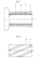
- the support system 7 according to the invention is, as shown in FIG. 1, arranged in the base body in such a way that it can be removed or exchanged and connected to the base body 1 in a form-fitting manner, the support system 7 being designed as a pressure pipe insert 2.
- the starting product for a pressure pipe insert 2 is a flat base element 5 made of a high-alloy stainless steel, Cr, Ti or Ni being used as alloying elements.
- the flat base element 5 is subjected to a cold deformation, the beads 6 being shaped out, in such a way that when the pressure tube insert 2 is formed as a result of the base element 5 being assembled into a cylindrical body, the beads 6 run along the pressure tube insert 2 which has formed and the trains 3 form.
- FIG. 2 shows a section of the flat basic element 5 and shows the obliquely molded beads 6, which then form as swirling trains 3 in the pressure pipe insert 2.
- FIG. 4 An advantageous embodiment of the use of the pressure tube insert 2 in the base body 1 is shown in FIG. 4.
- the pressure tube insert 2 is used in the base body 1 in such a way that a space 4 is provided between the two parts.
- This intermediate space 4 enables additional cooling of the material to be minced, in that a cooling medium can be introduced into this intermediate space 4, which can act directly on the material, since the existing wall thickness of the pressure tube insert 2 of approximately 1-3 mm permits good heat exchange.
- the intermediate space 4 can be used for the installation and arrangement of special functional elements.
- sensors can be arranged which directly record the prevailing operating conditions, which are fed to a central control unit, in order then to be usable as a control and control variable for the functional process of the grinder and for controlling the grinder.
- the pressure pipe insert 2 can also be formed from individual segments, a pressure pipe insert 2 made from two half-shells 8 most advantageously meeting the production and application-related and hygienic requirements.
- FIG. 5 shows a half-shell 8 with the already incorporated cables 3, which, when paired with a second half-shell 8, result in the complete pressure tube insert 2 and are used in this state in the base body 1 of the pressure tube.
- the half-shells 8 can be secured via a strip 9, which in turn engages in a groove 10 provided in the base body 1, as a result of which the entire pressure tube insert 2 is mounted in a manner that prevents it from rotating.
- the pressure pipe insert 2 is secured against axial displacement on the inlet side by the end face of the pressure pipe insert 2 in the pressure pipe, and on the outlet side it is secured by the union nut of the meat grinder, which also braces the cutting set parts.
- This design ensures the positive connection of the pressure pipe insert 2 and the base body 1 of the pressure pipe and enables easy removal or replacement, since no additional bracing and holding devices have to be released.
- the existing ejection device can be used to remove the pressure pipe insert 2.
- FIG. 6 shows a cage-like pressure pipe insert 2, which consists of spirally running spirals 11, which are delimited and fastened to the front by the disks 12; 13, and strips 11 are provided along the pressure pipe insert 2 on the outer periphery of the spirals 11, which are connected both to the disks 12, 13 and to the coils 11 and thus give the pressure tube insert 2 the required stability.
- the pressure tube insert 2 can also be secured against rotation in the form that a groove 14 is provided in the disc 12 provided on the outlet side, which locks the entire pressure tube insert 2 in the inserted state by the feather key 15, which is also required for receiving and securing the cutting set parts .
- a groove 14 is provided in the disc 12 provided on the outlet side, which locks the entire pressure tube insert 2 in the inserted state by the feather key 15, which is also required for receiving and securing the cutting set parts .
- the pressure pipe insert 2 is removed in the manner already described or by simply reaching behind the disk 12 and pulling it forward.
- both the pressure pipe insert 2 itself and the pressure pipe can be cleaned easily and comprehensively, no residual particles remain in or on the parts, 100% cleaning is possible, which in turn corresponds to the required hygiene condition.
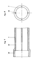
- a meat grinder with a pressure tube also fulfills this required hygienic condition, the base body 1 of which, as shown in FIGS. 9 and 10, consists of a high-alloy steel, in the flat starting product of which beads are incorporated and formed into a circular base body.
- the trains 16 resulting from the shaping to form a main body 1 are arranged on the circumferential side of the main body 1 and, depending on the shaping of the beads in the flat starting material, can have different train cross-sectional shapes.
- Trapezoidal cross-sections are shown, which are provided with curves, which has a very advantageous effect on the transport of the wolf material and at the same time has a positive effect on the cleaning process.
- the trains 16 can run both in a straight line and in a swirling manner and end on the outlet side in front of the respective cutting set.
- FIGS. 9 and 10 also show the assignment of a filling funnel 17 to the pressure pipe, which is of particular advantage in the case of small meat mincers.
Landscapes
- Engineering & Computer Science (AREA)
- Food Science & Technology (AREA)
- Meat, Egg Or Seafood Products (AREA)
- Finish Polishing, Edge Sharpening, And Grinding By Specific Grinding Devices (AREA)
- Crushing And Pulverization Processes (AREA)
Applications Claiming Priority (2)
| Application Number | Priority Date | Filing Date | Title |
|---|---|---|---|
| DE4406432 | 1994-02-28 | ||
| DE4406432 | 1994-02-28 |
Publications (2)
| Publication Number | Publication Date |
|---|---|
| EP0669165A1 true EP0669165A1 (fr) | 1995-08-30 |
| EP0669165B1 EP0669165B1 (fr) | 1998-12-16 |
Family
ID=6511372
Family Applications (1)
| Application Number | Title | Priority Date | Filing Date |
|---|---|---|---|
| EP95101765A Expired - Lifetime EP0669165B1 (fr) | 1994-02-28 | 1995-02-10 | Tube d'alimentation sous pression pour hachoir de viande |
Country Status (5)
| Country | Link |
|---|---|
| US (1) | US5628466A (fr) |
| EP (1) | EP0669165B1 (fr) |
| AT (1) | ATE174535T1 (fr) |
| DE (1) | DE19504354C2 (fr) |
| ES (1) | ES2127951T3 (fr) |
Families Citing this family (7)
| Publication number | Priority date | Publication date | Assignee | Title |
|---|---|---|---|---|
| DE19642232C2 (de) * | 1996-10-12 | 1999-03-18 | Inofex Fleisch Lebensmitteltec | Zerkleinerungs- und Emulgierautomat |
| DE19703249A1 (de) * | 1997-01-29 | 1998-07-30 | Heissenberger & Pretzler Gmbh | Vorrichtung und Aufbereitung von Bioabfall |
| US6168101B1 (en) | 1999-09-28 | 2001-01-02 | Premark Feg L.L.C. | Stainless steel chopper/mixer-grinder worm having improved resistance to fatting |
| CA2691955C (fr) * | 2007-06-26 | 2014-06-17 | Weiler And Company, Inc. | Broyeur a bloc congele |
| US7771256B1 (en) | 2008-08-05 | 2010-08-10 | Richburg James B | In-feed can |
| US9132579B2 (en) * | 2012-11-02 | 2015-09-15 | Davis-Standard, Llc | Extruder feed throat having hardened tiles on internal surfaces |
| GB2519536B (en) * | 2013-10-23 | 2017-09-06 | Kenwood Ltd | Foodstuff-grinding attachment for a kitchen machine |
Citations (4)
| Publication number | Priority date | Publication date | Assignee | Title |
|---|---|---|---|---|
| DE188414C (fr) * | ||||
| GB362428A (en) * | 1930-08-28 | 1931-11-30 | Alexander Jakowlewitch Moiseie | Improvements in and relating to mincing machines |
| DE642772C (de) * | 1937-03-15 | Hugo Simons Dr | Messerkorb fuer Fleischwoelfe | |
| US2524860A (en) * | 1946-04-05 | 1950-10-10 | Isadore N Vant | Meat grinder |
Family Cites Families (14)
| Publication number | Priority date | Publication date | Assignee | Title |
|---|---|---|---|---|
| DE287661C (fr) * | ||||
| US1904884A (en) * | 1933-04-18 | royle | ||
| FR757427A (fr) * | 1933-06-23 | 1933-12-26 | Ustensile de cuisine pourvu d'outils interchangeables de découpage et de pressage rotatifs disposés dans une enveloppe cylindrique | |
| DE620312C (de) * | 1933-10-01 | 1935-10-18 | Richard Heike Maschinenfabrik | Fleischwolf |
| CH184286A (de) * | 1935-08-23 | 1936-05-31 | Mueller & Cie Aktiengesellscha | Fleischwolf. |
| US2505797A (en) * | 1949-04-29 | 1950-05-02 | Globe Slicing Machine Co Inc | Meat chopper |
| DE1695425U (de) * | 1953-07-16 | 1955-03-24 | Reform Maschinenfabrik Paul Pa | Zerkleinerungsmaschine fuer lebensmittel. |
| DE1736489U (de) * | 1956-10-17 | 1956-12-20 | Bizerba Waagenfabrik Wilhelm K | Fleischwolf. |
| DE1061646B (de) * | 1957-03-23 | 1959-07-16 | Fernand Ravijts | Fleischwolf |
| US2910726A (en) * | 1957-08-20 | 1959-11-03 | Us Rubber Co | Pelletizing apparatus |
| US3734148A (en) * | 1971-10-15 | 1973-05-22 | Culty W Mc | Grinder |
| US3984056A (en) * | 1974-09-04 | 1976-10-05 | Hobart Corporation | Worm with deflector |
| FR2518282B1 (fr) * | 1981-12-16 | 1985-09-06 | Paturel Michel | Procede pour controler la temperature d'un appareil et appareils mettant en oeuvre un tel procede |
| DD287661A5 (de) * | 1989-09-06 | 1991-03-07 | Veb Wtoez Der Fleischindustrie,De | Druck- und foerderschnecke fuer fleischwoelfe |
-
1995
- 1995-02-10 DE DE19504354A patent/DE19504354C2/de not_active Expired - Fee Related
- 1995-02-10 EP EP95101765A patent/EP0669165B1/fr not_active Expired - Lifetime
- 1995-02-10 ES ES95101765T patent/ES2127951T3/es not_active Expired - Lifetime
- 1995-02-10 AT AT95101765T patent/ATE174535T1/de not_active IP Right Cessation
- 1995-02-22 US US08/392,050 patent/US5628466A/en not_active Expired - Fee Related
Patent Citations (4)
| Publication number | Priority date | Publication date | Assignee | Title |
|---|---|---|---|---|
| DE188414C (fr) * | ||||
| DE642772C (de) * | 1937-03-15 | Hugo Simons Dr | Messerkorb fuer Fleischwoelfe | |
| GB362428A (en) * | 1930-08-28 | 1931-11-30 | Alexander Jakowlewitch Moiseie | Improvements in and relating to mincing machines |
| US2524860A (en) * | 1946-04-05 | 1950-10-10 | Isadore N Vant | Meat grinder |
Also Published As
| Publication number | Publication date |
|---|---|
| ATE174535T1 (de) | 1999-01-15 |
| ES2127951T3 (es) | 1999-05-01 |
| DE19504354A1 (de) | 1995-09-07 |
| EP0669165B1 (fr) | 1998-12-16 |
| US5628466A (en) | 1997-05-13 |
| DE19504354C2 (de) | 1998-08-06 |
Similar Documents
| Publication | Publication Date | Title |
|---|---|---|
| DE3853352T2 (de) | Dispersions- und Zerkleinerungsapparat. | |
| DE2619157C2 (de) | Ringscheibenförmiger Mahlkörper zum Einbau in einen Refiner zur Aufbereitung von Faserstoffbrei insbesondere für die Papierherstellung | |
| DE3132048A1 (de) | Vorrichtung zum vereinzeln von gefaessen, insbesondere in gefaessbehandlungsmaschinen | |
| DE3905168C1 (fr) | ||
| DE4431959C1 (de) | Fleischwolf | |
| EP1356891B1 (fr) | Procédé de fabrication de manchons coulissants pour boítes de vitesses | |
| EP0669165B1 (fr) | Tube d'alimentation sous pression pour hachoir de viande | |
| DE2643307A1 (de) | Walzenmantel fuer mahlwalzen von walzenschuesselmuehlen | |
| DE102007049057A1 (de) | Messerkopf und Verfahren zum Herstellen eines Messerkopfes | |
| DE69903587T4 (de) | Verfahren zur Herstellung einer O-Ring-Halterung in Gegenständen unter Verwendung verriegelbarer Formen und Vorrichtung dafür | |
| DE2538228A1 (de) | Schleuderstrahlanlage | |
| DE2154353C2 (de) | Schneidmaschine für Fleischwaren o.dgl. | |
| EP0487539B1 (fr) | Cylindre de coupe ou cylindre d'estampage et procede pour leur fabrication | |
| DE1811614C3 (de) | Walzscheibenbefestigung für Draht-, Streckreduzler-Walzwerke und dergleichen Walzwerksmaschinen | |
| EP1132139B1 (fr) | Hachoir pour viande | |
| EP0647475B1 (fr) | Vis convoyeuse d'alimentation et de pression pour hachoir de viande | |
| DE919274C (de) | Verfahren zur Herstellung eines Spaltsiebes | |
| EP0765729B1 (fr) | Segment de vis pour extrudeuse et méthode de fabrication | |
| DE69813745T2 (de) | Zerkleinerer mit mehreren Schneiden für die Lebensmittelindustrie | |
| DE2853249C2 (de) | Schrämwalze für eine Gewinnungsmaschine des Kohlebergbaues | |
| EP2186591A1 (fr) | Tête de coupe et son procédé de fabrication | |
| DE4013128A1 (de) | Verfahren und vorrichtung zum ausfraesen der innenwand eines unterirdisch verlegten kanalrohres | |
| DE1632132A1 (de) | Verfahren und Einrichtung zur insbesondere sehr feinen Fleischzerkleinerung | |
| DE2747790C3 (de) | Raspelwerkzeug | |
| DE1557172C (de) | Vorrichtung zum Homogenisieren und Mischen |
Legal Events
| Date | Code | Title | Description |
|---|---|---|---|
| PUAI | Public reference made under article 153(3) epc to a published international application that has entered the european phase |
Free format text: ORIGINAL CODE: 0009012 |
|
| AK | Designated contracting states |
Kind code of ref document: A1 Designated state(s): AT BE CH ES FR GB IT LI NL |
|
| 17P | Request for examination filed |
Effective date: 19960208 |
|
| 17Q | First examination report despatched |
Effective date: 19980319 |
|
| GRAG | Despatch of communication of intention to grant |
Free format text: ORIGINAL CODE: EPIDOS AGRA |
|
| GRAG | Despatch of communication of intention to grant |
Free format text: ORIGINAL CODE: EPIDOS AGRA |
|
| GRAH | Despatch of communication of intention to grant a patent |
Free format text: ORIGINAL CODE: EPIDOS IGRA |
|
| GRAH | Despatch of communication of intention to grant a patent |
Free format text: ORIGINAL CODE: EPIDOS IGRA |
|
| GRAA | (expected) grant |
Free format text: ORIGINAL CODE: 0009210 |
|
| AK | Designated contracting states |
Kind code of ref document: B1 Designated state(s): AT BE CH ES FR GB IT LI NL |
|
| REF | Corresponds to: |
Ref document number: 174535 Country of ref document: AT Date of ref document: 19990115 Kind code of ref document: T |
|
| REG | Reference to a national code |
Ref country code: CH Ref legal event code: EP |
|
| ITF | It: translation for a ep patent filed | ||
| REG | Reference to a national code |
Ref country code: CH Ref legal event code: NV Representative=s name: A. BRAUN, BRAUN, HERITIER, ESCHMANN AG PATENTANWAE |
|
| PGFP | Annual fee paid to national office [announced via postgrant information from national office to epo] |
Ref country code: NL Payment date: 19990228 Year of fee payment: 5 |
|
| GBT | Gb: translation of ep patent filed (gb section 77(6)(a)/1977) |
Effective date: 19990212 |
|
| ET | Fr: translation filed | ||
| REG | Reference to a national code |
Ref country code: ES Ref legal event code: FG2A Ref document number: 2127951 Country of ref document: ES Kind code of ref document: T3 |
|
| PLBE | No opposition filed within time limit |
Free format text: ORIGINAL CODE: 0009261 |
|
| STAA | Information on the status of an ep patent application or granted ep patent |
Free format text: STATUS: NO OPPOSITION FILED WITHIN TIME LIMIT |
|
| 26N | No opposition filed | ||
| PG25 | Lapsed in a contracting state [announced via postgrant information from national office to epo] |
Ref country code: NL Free format text: LAPSE BECAUSE OF NON-PAYMENT OF DUE FEES Effective date: 20000901 |
|
| NLV4 | Nl: lapsed or anulled due to non-payment of the annual fee |
Effective date: 20000901 |
|
| REG | Reference to a national code |
Ref country code: GB Ref legal event code: IF02 |
|
| PGFP | Annual fee paid to national office [announced via postgrant information from national office to epo] |
Ref country code: CH Payment date: 20020218 Year of fee payment: 8 |
|
| PGFP | Annual fee paid to national office [announced via postgrant information from national office to epo] |
Ref country code: BE Payment date: 20020221 Year of fee payment: 8 |
|
| PG25 | Lapsed in a contracting state [announced via postgrant information from national office to epo] |
Ref country code: LI Free format text: LAPSE BECAUSE OF NON-PAYMENT OF DUE FEES Effective date: 20030228 Ref country code: CH Free format text: LAPSE BECAUSE OF NON-PAYMENT OF DUE FEES Effective date: 20030228 Ref country code: BE Free format text: LAPSE BECAUSE OF NON-PAYMENT OF DUE FEES Effective date: 20030228 |
|
| REG | Reference to a national code |
Ref country code: CH Ref legal event code: PL |
|
| PGFP | Annual fee paid to national office [announced via postgrant information from national office to epo] |
Ref country code: GB Payment date: 20041208 Year of fee payment: 11 |
|
| PGFP | Annual fee paid to national office [announced via postgrant information from national office to epo] |
Ref country code: FR Payment date: 20050218 Year of fee payment: 11 |
|
| PG25 | Lapsed in a contracting state [announced via postgrant information from national office to epo] |
Ref country code: GB Free format text: LAPSE BECAUSE OF NON-PAYMENT OF DUE FEES Effective date: 20060210 |
|
| GBPC | Gb: european patent ceased through non-payment of renewal fee |
Effective date: 20060210 |
|
| REG | Reference to a national code |
Ref country code: FR Ref legal event code: ST Effective date: 20061031 |
|
| PG25 | Lapsed in a contracting state [announced via postgrant information from national office to epo] |
Ref country code: FR Free format text: LAPSE BECAUSE OF NON-PAYMENT OF DUE FEES Effective date: 20060228 |
|
| PGFP | Annual fee paid to national office [announced via postgrant information from national office to epo] |
Ref country code: AT Payment date: 20080222 Year of fee payment: 14 |
|
| PG25 | Lapsed in a contracting state [announced via postgrant information from national office to epo] |
Ref country code: AT Free format text: LAPSE BECAUSE OF NON-PAYMENT OF DUE FEES Effective date: 20090210 |
|
| PGFP | Annual fee paid to national office [announced via postgrant information from national office to epo] |
Ref country code: IT Payment date: 20110224 Year of fee payment: 17 |
|
| PGFP | Annual fee paid to national office [announced via postgrant information from national office to epo] |
Ref country code: ES Payment date: 20110221 Year of fee payment: 17 |
|
| PG25 | Lapsed in a contracting state [announced via postgrant information from national office to epo] |
Ref country code: IT Free format text: LAPSE BECAUSE OF NON-PAYMENT OF DUE FEES Effective date: 20120210 |
|
| REG | Reference to a national code |
Ref country code: ES Ref legal event code: FD2A Effective date: 20130708 |
|
| PG25 | Lapsed in a contracting state [announced via postgrant information from national office to epo] |
Ref country code: ES Free format text: LAPSE BECAUSE OF NON-PAYMENT OF DUE FEES Effective date: 20120211 |