EP0669571B1 - Procédé et dispositif d'enregistrement/reproduction d'information - Google Patents
Procédé et dispositif d'enregistrement/reproduction d'information Download PDFInfo
- Publication number
- EP0669571B1 EP0669571B1 EP95301085A EP95301085A EP0669571B1 EP 0669571 B1 EP0669571 B1 EP 0669571B1 EP 95301085 A EP95301085 A EP 95301085A EP 95301085 A EP95301085 A EP 95301085A EP 0669571 B1 EP0669571 B1 EP 0669571B1
- Authority
- EP
- European Patent Office
- Prior art keywords
- information
- command
- recording medium
- track
- sector
- Prior art date
- Legal status (The legal status is an assumption and is not a legal conclusion. Google has not performed a legal analysis and makes no representation as to the accuracy of the status listed.)
- Expired - Lifetime
Links
Images


Classifications
-
- G—PHYSICS
- G06—COMPUTING OR CALCULATING; COUNTING
- G06F—ELECTRIC DIGITAL DATA PROCESSING
- G06F11/00—Error detection; Error correction; Monitoring
- G06F11/07—Responding to the occurrence of a fault, e.g. fault tolerance
- G06F11/0703—Error or fault processing not based on redundancy, i.e. by taking additional measures to deal with the error or fault not making use of redundancy in operation, in hardware, or in data representation
- G06F11/0766—Error or fault reporting or storing
- G06F11/0775—Content or structure details of the error report, e.g. specific table structure, specific error fields
-
- G—PHYSICS
- G06—COMPUTING OR CALCULATING; COUNTING
- G06F—ELECTRIC DIGITAL DATA PROCESSING
- G06F11/00—Error detection; Error correction; Monitoring
- G06F11/07—Responding to the occurrence of a fault, e.g. fault tolerance
- G06F11/0703—Error or fault processing not based on redundancy, i.e. by taking additional measures to deal with the error or fault not making use of redundancy in operation, in hardware, or in data representation
- G06F11/0706—Error or fault processing not based on redundancy, i.e. by taking additional measures to deal with the error or fault not making use of redundancy in operation, in hardware, or in data representation the processing taking place on a specific hardware platform or in a specific software environment
- G06F11/0745—Error or fault processing not based on redundancy, i.e. by taking additional measures to deal with the error or fault not making use of redundancy in operation, in hardware, or in data representation the processing taking place on a specific hardware platform or in a specific software environment in an input/output transactions management context
-
- G—PHYSICS
- G06—COMPUTING OR CALCULATING; COUNTING
- G06F—ELECTRIC DIGITAL DATA PROCESSING
- G06F3/00—Input arrangements for transferring data to be processed into a form capable of being handled by the computer; Output arrangements for transferring data from processing unit to output unit, e.g. interface arrangements
- G06F3/06—Digital input from, or digital output to, record carriers, e.g. RAID, emulated record carriers or networked record carriers
- G06F3/0601—Interfaces specially adapted for storage systems
-
- G—PHYSICS
- G06—COMPUTING OR CALCULATING; COUNTING
- G06F—ELECTRIC DIGITAL DATA PROCESSING
- G06F3/00—Input arrangements for transferring data to be processed into a form capable of being handled by the computer; Output arrangements for transferring data from processing unit to output unit, e.g. interface arrangements
- G06F3/06—Digital input from, or digital output to, record carriers, e.g. RAID, emulated record carriers or networked record carriers
- G06F3/08—Digital input from, or digital output to, record carriers, e.g. RAID, emulated record carriers or networked record carriers from or to individual record carriers, e.g. punched card, memory card, integrated circuit [IC] card or smart card
-
- G—PHYSICS
- G11—INFORMATION STORAGE
- G11B—INFORMATION STORAGE BASED ON RELATIVE MOVEMENT BETWEEN RECORD CARRIER AND TRANSDUCER
- G11B20/00—Signal processing not specific to the method of recording or reproducing; Circuits therefor
- G11B20/10—Digital recording or reproducing
- G11B20/18—Error detection or correction; Testing, e.g. of drop-outs
- G11B20/1879—Direct read-after-write methods
Definitions
- the present invention relates to an information recording/reproducing method for recording/reproducing predetermined information on/from an information recording medium in accordance with commands sent from a host computer via a SCSI (Small Computer System Interface).
- SCSI Small Computer System Interface
- a SCSI was standardized as ANSI X3. 131-1986 after deliberation at the X3T9.2 committee of the ANSI (American National Standards Institute) on the basis of an interface SASI (Shugart Associates System Interface) for connection between small computers and their peripheral devices available from Shugart, U.S.A.
- the SCSI has been increasingly accepted as a standard interface for connection, between personal computers and their peripheral devices.
- the range of the SCSI rules defined by the ANSI includes the following five points:
- the command system in item (4) is defined as follows. SCSI commands are classified into eight groups. The first byte of a CDB (Command Description Block) is an operation code. The upper three bits of this code designate a group code; and the lower five bits, a command code (a code indicating the type of command) for each group. The lengths of CDBs in the respective groups are defined as follows:
- CDBs in groups 6 and 7 are command groups which can be uniquely defined by each SCSI device.
- In the logical block address of each command fixed-length data blocks are consecutively arranged on a logical unit.
- Fig. 1 shows the format of logical blocks in a hard disk unit.
- the advantage of a logical block address is that no physical structure needs to be considered because an initiator (host computer) accesses data by designating the logical block address of the first data block and the number of blocks to be processed. With the use of logical block addresses, therefore, when devices based on different specifications concerning the numbers of cylinders, tracks, sectors, and the like are connected to each other, they can be operated by the same software.
- Fig. 2 shows the arrangement of a general SCSI system.
- a physical device such as a hard disk like the one shown in Fig. 1 is generally connected as a logical unit
- a logical unit number LUN
- LUN logical unit number
- eight logical units of LUN 0 to 7 can be connected to a SCSI bus.
- an extension message a maximum of 2,048 logical units can be connected.
- a CDB of a SCSI command consists of six bytes or more.
- Fig. 3 shows a CDB of a Write command in group 0.
- Logical Unit Number indicates a logical unit for which the command is issued;
- Logical Block Address a logical block of the command which is to be executed first;
- Transfer Length the number of logical blocks to be executed consecutively.
- a Write command is issued.
- data is recorded in consecutive logical blocks, of a logical unit indicated by the Logical Unit Number bits, which ranges from a logical block indicated by the Logical Block Address bytes to a logical block indicated by the Transfer Length byte.
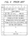
- Sense Key indicates the type of error; and Information Bytes, the location (logical block) of an error. Additional Sense Length indicates the number of bytes of sense data added after byte 8. Sense Code indicates the detailed information of an error.
- the target upon reception of a command with respect to a plurality of logical blocks, the target generally sets sense data and terminates the command by sending a check condition status when an error is caused.
- a Read command with respect to five consecutive logical blocks from logical block 1 to logical block 5.
- the target sets Sense Key to 3H (Medium Error); Sense Code to 11H (Read Error); Information Bytes to 3 (indicating a logical block in which the error has occurred); Valid to 1 (indicating the Information Bytes are valid) in sense data, and returns a check condition status to the initiator.
- the initiator receives the sense data by issuing a request status command, and issues a Read command again with respect to logical block 3 indicated by the Information Bytes. With this operation, a retry with respect to the error can be performed .
- Information Bytes generally indicate a logical block address for which the initiator should perform a retry next.
- Optical information recording media are available in various forms, e.g., disk-like, card-like, and tape-like forms.
- a card-like optical information recording medium (to be referred to as an optical card hereinafter) is expected to be in great demand as an information recording medium which is compact and lightweight and hence can be easily carried, and has a relatively large capacity.
- Information recording media are classified into erasable, rewritable media and media which allows no such operations.
- Optical cards are generally used as media which are not erasable nor rewritable. Therefore, optical cards are expected to be used in the medical field and the like in which the above characteristic is considered as an advantage.
- the optical card and a light beam for a recording/reproducing operation are reciprocated relative to each other to record/reproduce information on/from the recording surface of the optical card.
- light beam control techniques such as automatic focusing (AF) and automatic tracking (AT) are used to position a light beam on a track on a recording surface.
- logical blocks When a plurality of logical blocks (sectors) are arranged on one track as is the case with an optical card or optical disk, logical blocks present on the same track within a logical block range defined by a CDB of a command are subjected to write processing at once, and the written data are verified at once, instead of writing and verifying in units of sectors. Since the processing time can be shortened by performing processing in units of tracks, this method is generally used. Assume that logical blocks present on the same track are processed at once.
- a Write and Verify command is issued with respect to a plurality of logical blocks, and verify errors occur in a plurality of logical blocks in a logical block range designated by a CDB of a command.
- a logical block address at which an error has occurred first from the viewpoint of a command i.e., in general, the smallest address of the logical blocks at which the errors have occurred, is set in Information Bytes.
- the present invention has been made in consideration of the above conventional problems, and has as its object to provide an information recording/reproducing method capable of greatly shortening the processing time in the event of an error.
- EP-A-0 524 810 discloses a method of recording information on a recording medium in response to a recording command from a host computer connected to the apparatus via a Small Computer System Interface. Where an error occurs during the recording of information, Sense Data generated includes information indicative of the address of the last logical block in which the recording was successfully executed before the recording stopped.
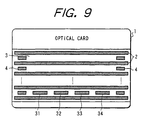
- FIG. 9 is a plan view showing an example of this optical card.
- a plurality of tracking tracks 2 are arranged on an optical card 1 to be parallel to each other, and data tracks 3 are arranged between the respective tracking tracks 2.
- Physical track numbers 4 indicating the physical position of each data track 3 are pre-formatted on the two ends of the data track 3.
- Four sectors 31, 32, 33, and 34 (corresponding to sector numbers 1 to 4 on each track) are arranged on each data track 3.
- Physical track number 4 is 0 on the lower end side of the optical card 1 and sequentially incremented toward the upper end side of the optical card 1 up to 2,499 on the uppermost end. That is, 2,500 data tracks 3 are arranged on the optical card 1, and a total of 10,000 sectors are arranged on the tracks.
- the sectors on the optical card 1 correspond to the logical blocks of a SCSI.
- Sector 1 of physical track 0 corresponds to logical block 0; sector 4 of physical track 0, logical block 3; and sector 4 of physical track 2,499, logical block 9,999.
- a plurality of sector types of different sector sizes can be supported.
- the number of sectors arranged on one track is not limited to four, it is assumed in the following description that four sectors are arranged on one track, as shown in Fig. 9.
- Fig. 10 is a block diagram showing a SCSI system.
- a SCSI controller 5 serves as a target.
- the SCSI controller 5 is constituted by a SCSI protocol circuit (SPC) 6 for performing sequence control of a SCSI signal on the basis of the SCSI standards, an MPU 8 as a control unit for controlling the SCSI controller 5 in accordance with programs stored in a ROM 7, and a RAM 9 used as a buffer memory for recording/reproducing data or used to stored sense data.
- An information recording/reproducing apparatus 10 is connected to the SCSI controller 5.
- the optical card 1 described with reference to Fig. 9 is inserted in the information recording/reproducing apparatus 10, and information is recorded or reproduced in accordance with a command from a host computer 12.
- This system also includes a host adaptor 13.
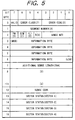
- Fig. 5 shows sense data used in this embodiment.
- the following pieces of information are set in sense data to be set.
- the smallest address of the logical blocks at which the errors have occurred is set in Information Bytes, and status information of all the sectors on a track on the optical track including a logical block corresponding to the logical block address set in the Information Bytes is set in Sector Status bytes in units of sectors.
- Sector Status bytes in units of sectors.
- Fig. 6 shows the format of a sector status byte in sense data.
- "Valid" at bit 7 indicates whether the corresponding byte is valid.
- Bit 7 of a byte corresponding to a sector which is not a target for a command becomes 0.
- Physical Sector Number at bits 0 to 3 indicates the physical sector number indicated by the byte.
- "Scan" at bit 4 indicates whether a light beam is scanned on a physical sector indicated by the byte, i.e., whether a recording/reproducing operation with respect to the sector is performed.
- R/V Status 11, an ECC decode error/verify error.
- FIG. 7 and 8 shows a recorded state of data on the optical card 1.
- An information recording/reproducing method of this embodiment will be described below with reference to these drawings.
- each rectangle drawn in a solid line indicates a logical block (sector) on which data is recorded; each rectangle drawn in a dotted line, a logical block on which no data is recorded; a number in each rectangle, a logical block address; and each sign "x", the location of an error.
- data have already been recorded on blocks 0 to 3 in the case shown in Fig. 7, and data have already been recorded on blocks 0 to 6 in the case shown in Fig. 8.
- verify processing is generally performed in the opposite direction to recording processing in a recording/reproducing apparatus using an optical card. Assume, therefore, that recording processing is performed in the order of logical blocks 4, 5, 6, and 7, and verify processing is performed in the order of logical blocks 7, 6, 5, and 4.
- the SCSI controller 5 sets sense data in the RAM 9 and returns a check condition status to the host computer 12 via the SCSI bus.
- "4" indicating a logical block address at which an error has occurred is set in Information Bytes in the sense data.
- the status information of all the sectors on the same track as that of logical block 4 set in the Information Bytes is respectively set in bytes 13 to 16 of the sense data. These values are E1H, 82H, 83H, and 84H, respectively.
- 3H Medium Error
- OCH Write Error
- the host computer 12 can determine from bytes 13 to 16 that an error has occurred only at one block, and physical sector 1 indicated by byte 13 is logical block 4 indicated by the Information Bytes.
- the host computer 12 since it is known that a Write and Verify command with respect to three blocks indicated by bytes 14 to 16, i.e., logical blocks 5 to 7, has terminated normally, the host computer 12 need only perform a retry operation with respect to logical block 4 indicated by the Information Bytes, but need not perform a retry operation with respect to logical blocks 5 to 7.
- the SCSI controller 5 sets sense data in the RAM 9, and returns a check condition status to the host computer 12 via the SCSI bus.
- Information Bytes in the sense data "4" indicating the smallest address among logical block addresses at which the error has occurred is set.
- the host computer 12 can determine from bytes 13 to 16 that errors have occurred at two blocks, and physical sector 1 indicated by byte 13 is logical block 4 indicated by the Information Bytes. In addition, the host computer 12 can determine that the command has terminated normally with respect to physical sector 3 indicated by byte 14, i.e., logical block 5. Therefore, the host computer 12 need only perform a retry operation with respect to logical block 6 indicated by byte 15 of the sense sense but need not perform a retry operation with respect to logical block 5.
- the number of bytes used for Sector Status may be changed in accordance with the number of sectors arranged on one track which is determined by the sector type used for recording/reproduction processing upon issuing of a command associated with recording/reproduction processing. In any case, it suffices to ensure the number of bytes is large enough to store status information associated with all the sectors arranged on one track.
- the present invention when an error occurs during execution of a command such as a Read, Write and Verify, or Verify command, which is accompanied by at least a reproducing operation, the following pieces of information are set in sense data.
- the smallest logical block addresses among logical blocks at which the error has occurred is set in an Information Byte of the sense data.
- status information of all the sectors present on a track of the information recording medium which includes a logical block corresponding to the address set in the Information Bytes is set in units of sectors independently of the Information Bytes in the sense data. Therefore, information required for an initiator to perform a retry can be provided, and the initiator need not perform unnecessary retry processing, thereby greatly shortening the processing time as compared with the prior art.
Landscapes
- Engineering & Computer Science (AREA)
- Theoretical Computer Science (AREA)
- Physics & Mathematics (AREA)
- General Engineering & Computer Science (AREA)
- General Physics & Mathematics (AREA)
- Human Computer Interaction (AREA)
- Quality & Reliability (AREA)
- Microelectronics & Electronic Packaging (AREA)
- Signal Processing (AREA)
- Signal Processing For Digital Recording And Reproducing (AREA)
- Debugging And Monitoring (AREA)
Claims (7)
- Procédé de reproduction d'information enregistrée sur une piste d'un support (1) d'enregistrement d'information comportant une pluralité de pistes (3), un ou plusieurs secteurs (31, 32, 33, 34) étant agencés sur chaque piste (3), en fonction d'une instruction provenant d'un ordinateur hôte (12) par l'intermédiaire d'une Interface pour Petits Systèmes Informatiques ;
dans lequel, lorsqu'une erreur (X) se produit pendant l'exécution d'une instruction durant la reproduction d'information provenant dudit support (1) d'enregistrement d'information, l'instruction se termine en utilisant un état de Condition de Contrôle et l'on prend comme Donnée Lue une Information d'Etat de Secteur de tous les secteurs (31, 32, 33, 34) d'une piste du support d'enregistrement d'information incluant un bloc logique (4 ; 4, 7) dans lequel l'erreur (X) s'est produite, l'Information d'Etat de Secteur incluant une indication du fait que l'on a reproduit de l'information provenant de chaque secteur. - Procédé selon la revendication 1, incluant l'étape consistant à enregistrer de l'information sur le support d'enregistrement, dans lequel ladite étape de reproduction d'information est une étape de vérification consistant à vérifier de l'information enregistrée pendant l'étape d'enregistrement.
- Procédé selon la revendication 1 ou 2, dans lequel ledit support (1) est un support d'enregistrement d'information du type carte.
- Appareil destiné à reproduire de l'information enregistrée sur une piste d'un support (1) d'enregistrement d'information comportant une pluralité de pistes (3), un ou plusieurs secteurs (31, 32, 33, 34) étant agencés sur chaque piste (3), en fonction d'une instruction provenant d'un ordinateur hôte (12) relié à l'appareil par l'intermédiaire d'une Interface pour Petits Systèmes Informatiques ;
dans lequel, lorsqu'une erreur (X) se produit pendant l'exécution d'une instruction durant la reproduction d'information provenant dudit support (1) d'enregistrement d'information, l'appareil inclut un moyen (5) destiné à mettre fin à l'instruction en utilisant un état de Condition de Contrôle et l'on prend comme Donnée Lue une Information d'Etat de Secteur de tous les secteurs (31, 32, 33, 34) d'une , piste du support d'enregistrement d'information incluant un bloc logique (4 ; 4, 7) dans lequel l'erreur (X) s'est produite, l'Information d'Etat de Secteur incluant une indication du fait que l'on a reproduit de l'information provenant de chaque secteur. - Appareil selon la revendication 4, incluant un moyen destiné à enregistrer de l'information sur le support (1) d'enregistrement, ladite reproduction d'information étant la vérification de l'information enregistrée au cours de l'enregistrement.
- Appareil selon la revendication 4 ou 5, dans lequel ledit support (1) est un support d'enregistrement d'information du type carte.
- Produit programme d'ordinateur mettant en oeuvre des instructions lisibles en machine pour faire qu'un appareil destiné à reproduire de l'information mette en oeuvre un procédé selon l'une quelconque des revendications 1 à 3.
Applications Claiming Priority (3)
| Application Number | Priority Date | Filing Date | Title |
|---|---|---|---|
| JP2514794 | 1994-02-23 | ||
| JP25147/94 | 1994-02-23 | ||
| JP06025147A JP3128102B2 (ja) | 1994-02-23 | 1994-02-23 | 情報記録再生方式 |
Publications (2)
| Publication Number | Publication Date |
|---|---|
| EP0669571A1 EP0669571A1 (fr) | 1995-08-30 |
| EP0669571B1 true EP0669571B1 (fr) | 2001-05-02 |
Family
ID=12157893
Family Applications (1)
| Application Number | Title | Priority Date | Filing Date |
|---|---|---|---|
| EP95301085A Expired - Lifetime EP0669571B1 (fr) | 1994-02-23 | 1995-02-21 | Procédé et dispositif d'enregistrement/reproduction d'information |
Country Status (4)
| Country | Link |
|---|---|
| US (1) | US5619481A (fr) |
| EP (1) | EP0669571B1 (fr) |
| JP (1) | JP3128102B2 (fr) |
| DE (1) | DE69520805T2 (fr) |
Families Citing this family (3)
| Publication number | Priority date | Publication date | Assignee | Title |
|---|---|---|---|---|
| US6170066B1 (en) * | 1995-09-29 | 2001-01-02 | Intel Corporation | Power-off recovery management for sector based flash media managers |
| US6942151B2 (en) * | 2001-05-15 | 2005-09-13 | Welch Allyn Data Collection, Inc. | Optical reader having decoding and image capturing functionality |
| US7739462B2 (en) * | 2005-02-23 | 2010-06-15 | International Business Machines Corporation | Policy based data shredding for storage controller |
Family Cites Families (4)
| Publication number | Priority date | Publication date | Assignee | Title |
|---|---|---|---|---|
| JPH02193335A (ja) * | 1989-01-20 | 1990-07-31 | Csk Corp | カード型光記録媒体 |
| JPH0527915A (ja) * | 1991-07-23 | 1993-02-05 | Canon Inc | 情報記録再生方式 |
| JP3132677B2 (ja) * | 1991-07-23 | 2001-02-05 | キヤノン株式会社 | 情報記録再生方法 |
| JPH0689446A (ja) * | 1992-09-07 | 1994-03-29 | Olympus Optical Co Ltd | 光学的情報記録再生装置及びトラックジャンプ方法 |
-
1994
- 1994-02-23 JP JP06025147A patent/JP3128102B2/ja not_active Expired - Fee Related
-
1995
- 1995-02-21 EP EP95301085A patent/EP0669571B1/fr not_active Expired - Lifetime
- 1995-02-21 DE DE69520805T patent/DE69520805T2/de not_active Expired - Fee Related
- 1995-02-22 US US08/394,165 patent/US5619481A/en not_active Expired - Fee Related
Also Published As
| Publication number | Publication date |
|---|---|
| JPH07234762A (ja) | 1995-09-05 |
| EP0669571A1 (fr) | 1995-08-30 |
| JP3128102B2 (ja) | 2001-01-29 |
| US5619481A (en) | 1997-04-08 |
| DE69520805T2 (de) | 2001-10-18 |
| DE69520805D1 (de) | 2001-06-07 |
Similar Documents
| Publication | Publication Date | Title |
|---|---|---|
| EP0221763B1 (fr) | Système pour le transfert de données numériques entre un dispositif hôte et un support d'enregistrement | |
| US4885683A (en) | Self-testing peripheral-controller system | |
| US5887128A (en) | Method and apparatus for redundant disk storage system with offset | |
| EP0524809B1 (fr) | Méthode de mise en oeuvre soit d'enregistrement ou soit de reproduction de données en utilisant un système de traitement d'information | |
| EP0077007B1 (fr) | Dispositif de mémoire supplémentaire utilisant des communications en série entre unités de commande et de contrôle | |
| US7475279B2 (en) | Data storage system, data storage control device, and write error diagnosis method for disks thereof | |
| EP0524810B1 (fr) | Enregistrement d'information envoyé par un ordinateur hÔte sur un bus SCSI | |
| KR100391740B1 (ko) | 재생 오류의 처리 방법 및 이를 이용한 디스크 장치 | |
| EP0669571B1 (fr) | Procédé et dispositif d'enregistrement/reproduction d'information | |
| US7418570B2 (en) | Logical unit number increasing device, and logical unit number increasing method | |
| EP0974910A2 (fr) | Méthode et appareil pour le stockage de données de limites récupérable, dans une mémoire tampon d'un dispositif recepteur | |
| EP1198891B1 (fr) | Gestion d'integrite de donnees pour systemes de stockage de donnees | |
| JP3613722B2 (ja) | ディスクアレイ装置 | |
| JP3275492B2 (ja) | 連動型ディスク装置 | |
| EP0878756A2 (fr) | Disque magnétique et appareil de commande de disque magnétique | |
| JP3102080B2 (ja) | ディスクアレイ装置 | |
| JPS61133433A (ja) | 書換え不能なデ−タ記録媒体における不良セクタ代替え処理方式 | |
| JP2665768B2 (ja) | 情報記録再生方法 | |
| Specification | HITACHI3. 5 INCH MAGNETIC DISK DRIVE | |
| JPH05189346A (ja) | ディスク制御装置 | |
| JPH06162684A (ja) | 情報記録/再生方式 | |
| JPH05324499A (ja) | Scsiデータ転送方式及び情報記録制御方式 | |
| JPH04285773A (ja) | 外部記憶装置 | |
| JPH0376059A (ja) | 磁気ディスク装置 | |
| JPH09258911A (ja) | ディスクアレイ装置 |
Legal Events
| Date | Code | Title | Description |
|---|---|---|---|
| PUAI | Public reference made under article 153(3) epc to a published international application that has entered the european phase |
Free format text: ORIGINAL CODE: 0009012 |
|
| AK | Designated contracting states |
Kind code of ref document: A1 Designated state(s): DE FR GB IT NL |
|
| 17P | Request for examination filed |
Effective date: 19960111 |
|
| 17Q | First examination report despatched |
Effective date: 19980810 |
|
| GRAG | Despatch of communication of intention to grant |
Free format text: ORIGINAL CODE: EPIDOS AGRA |
|
| RIC1 | Information provided on ipc code assigned before grant |
Free format text: 6G 06F 3/06 A, 6G 06F 11/22 B, 6G 11B 20/18 B, 6G 06F 11/00 B |
|
| RTI1 | Title (correction) |
Free format text: INFORMATION RECORDING/REPRODUCING METHOD AND APPARATUS |
|
| GRAG | Despatch of communication of intention to grant |
Free format text: ORIGINAL CODE: EPIDOS AGRA |
|
| GRAG | Despatch of communication of intention to grant |
Free format text: ORIGINAL CODE: EPIDOS AGRA |
|
| GRAH | Despatch of communication of intention to grant a patent |
Free format text: ORIGINAL CODE: EPIDOS IGRA |
|
| GRAH | Despatch of communication of intention to grant a patent |
Free format text: ORIGINAL CODE: EPIDOS IGRA |
|
| GRAA | (expected) grant |
Free format text: ORIGINAL CODE: 0009210 |
|
| AK | Designated contracting states |
Kind code of ref document: B1 Designated state(s): DE FR GB IT NL |
|
| PG25 | Lapsed in a contracting state [announced via postgrant information from national office to epo] |
Ref country code: NL Free format text: LAPSE BECAUSE OF FAILURE TO SUBMIT A TRANSLATION OF THE DESCRIPTION OR TO PAY THE FEE WITHIN THE PRESCRIBED TIME-LIMIT Effective date: 20010502 Ref country code: IT Free format text: LAPSE BECAUSE OF FAILURE TO SUBMIT A TRANSLATION OF THE DESCRIPTION OR TO PAY THE FEE WITHIN THE PRESCRIBED TIME-LIMIT;WARNING: LAPSES OF ITALIAN PATENTS WITH EFFECTIVE DATE BEFORE 2007 MAY HAVE OCCURRED AT ANY TIME BEFORE 2007. THE CORRECT EFFECTIVE DATE MAY BE DIFFERENT FROM THE ONE RECORDED. Effective date: 20010502 |
|
| REF | Corresponds to: |
Ref document number: 69520805 Country of ref document: DE Date of ref document: 20010607 |
|
| ET | Fr: translation filed | ||
| NLV1 | Nl: lapsed or annulled due to failure to fulfill the requirements of art. 29p and 29m of the patents act | ||
| REG | Reference to a national code |
Ref country code: GB Ref legal event code: IF02 |
|
| PLBE | No opposition filed within time limit |
Free format text: ORIGINAL CODE: 0009261 |
|
| 26N | No opposition filed | ||
| PGFP | Annual fee paid to national office [announced via postgrant information from national office to epo] |
Ref country code: GB Payment date: 20070214 Year of fee payment: 13 |
|
| PGFP | Annual fee paid to national office [announced via postgrant information from national office to epo] |
Ref country code: DE Payment date: 20070418 Year of fee payment: 13 |
|
| PGFP | Annual fee paid to national office [announced via postgrant information from national office to epo] |
Ref country code: FR Payment date: 20070221 Year of fee payment: 13 |
|
| GBPC | Gb: european patent ceased through non-payment of renewal fee |
Effective date: 20080221 |
|
| REG | Reference to a national code |
Ref country code: FR Ref legal event code: ST Effective date: 20081031 |
|
| PG25 | Lapsed in a contracting state [announced via postgrant information from national office to epo] |
Ref country code: DE Free format text: LAPSE BECAUSE OF NON-PAYMENT OF DUE FEES Effective date: 20080902 |
|
| PG25 | Lapsed in a contracting state [announced via postgrant information from national office to epo] |
Ref country code: FR Free format text: LAPSE BECAUSE OF NON-PAYMENT OF DUE FEES Effective date: 20080229 |
|
| PG25 | Lapsed in a contracting state [announced via postgrant information from national office to epo] |
Ref country code: GB Free format text: LAPSE BECAUSE OF NON-PAYMENT OF DUE FEES Effective date: 20080221 |