EP0077007B1 - Dispositif de mémoire supplémentaire utilisant des communications en série entre unités de commande et de contrôle - Google Patents
Dispositif de mémoire supplémentaire utilisant des communications en série entre unités de commande et de contrôle Download PDFInfo
- Publication number
- EP0077007B1 EP0077007B1 EP82109213A EP82109213A EP0077007B1 EP 0077007 B1 EP0077007 B1 EP 0077007B1 EP 82109213 A EP82109213 A EP 82109213A EP 82109213 A EP82109213 A EP 82109213A EP 0077007 B1 EP0077007 B1 EP 0077007B1
- Authority
- EP
- European Patent Office
- Prior art keywords
- drive
- controller
- command
- format
- byte
- Prior art date
- Legal status (The legal status is an assumption and is not a legal conclusion. Google has not performed a legal analysis and makes no representation as to the accuracy of the status listed.)
- Expired
Links
Images


Classifications
-
- G—PHYSICS
- G06—COMPUTING OR CALCULATING; COUNTING
- G06F—ELECTRIC DIGITAL DATA PROCESSING
- G06F11/00—Error detection; Error correction; Monitoring
- G06F11/07—Responding to the occurrence of a fault, e.g. fault tolerance
- G06F11/14—Error detection or correction of the data by redundancy in operations
- G06F11/1402—Saving, restoring, recovering or retrying
- G06F11/1415—Saving, restoring, recovering or retrying at system level
- G06F11/1443—Transmit or communication errors
-
- G—PHYSICS
- G06—COMPUTING OR CALCULATING; COUNTING
- G06F—ELECTRIC DIGITAL DATA PROCESSING
- G06F3/00—Input arrangements for transferring data to be processed into a form capable of being handled by the computer; Output arrangements for transferring data from processing unit to output unit, e.g. interface arrangements
- G06F3/06—Digital input from, or digital output to, record carriers, e.g. RAID, emulated record carriers or networked record carriers
- G06F3/0601—Interfaces specially adapted for storage systems
- G06F3/0628—Interfaces specially adapted for storage systems making use of a particular technique
- G06F3/0655—Vertical data movement, i.e. input-output transfer; data movement between one or more hosts and one or more storage devices
- G06F3/0659—Command handling arrangements, e.g. command buffers, queues, command scheduling
-
- G—PHYSICS
- G06—COMPUTING OR CALCULATING; COUNTING
- G06F—ELECTRIC DIGITAL DATA PROCESSING
- G06F11/00—Error detection; Error correction; Monitoring
- G06F11/07—Responding to the occurrence of a fault, e.g. fault tolerance
- G06F11/0703—Error or fault processing not based on redundancy, i.e. by taking additional measures to deal with the error or fault not making use of redundancy in operation, in hardware, or in data representation
- G06F11/0706—Error or fault processing not based on redundancy, i.e. by taking additional measures to deal with the error or fault not making use of redundancy in operation, in hardware, or in data representation the processing taking place on a specific hardware platform or in a specific software environment
- G06F11/0727—Error or fault processing not based on redundancy, i.e. by taking additional measures to deal with the error or fault not making use of redundancy in operation, in hardware, or in data representation the processing taking place on a specific hardware platform or in a specific software environment in a storage system, e.g. in a DASD or network based storage system
-
- G—PHYSICS
- G06—COMPUTING OR CALCULATING; COUNTING
- G06F—ELECTRIC DIGITAL DATA PROCESSING
- G06F11/00—Error detection; Error correction; Monitoring
- G06F11/07—Responding to the occurrence of a fault, e.g. fault tolerance
- G06F11/0703—Error or fault processing not based on redundancy, i.e. by taking additional measures to deal with the error or fault not making use of redundancy in operation, in hardware, or in data representation
- G06F11/0793—Remedial or corrective actions
-
- G—PHYSICS
- G06—COMPUTING OR CALCULATING; COUNTING
- G06F—ELECTRIC DIGITAL DATA PROCESSING
- G06F13/00—Interconnection of, or transfer of information or other signals between, memories, input/output devices or central processing units
- G06F13/38—Information transfer, e.g. on bus
- G06F13/42—Bus transfer protocol, e.g. handshake; Synchronisation
- G06F13/4204—Bus transfer protocol, e.g. handshake; Synchronisation on a parallel bus
- G06F13/4221—Bus transfer protocol, e.g. handshake; Synchronisation on a parallel bus being an input/output bus, e.g. ISA bus, EISA bus, PCI bus, SCSI bus
- G06F13/423—Bus transfer protocol, e.g. handshake; Synchronisation on a parallel bus being an input/output bus, e.g. ISA bus, EISA bus, PCI bus, SCSI bus with synchronous protocol
-
- G—PHYSICS
- G06—COMPUTING OR CALCULATING; COUNTING
- G06F—ELECTRIC DIGITAL DATA PROCESSING
- G06F3/00—Input arrangements for transferring data to be processed into a form capable of being handled by the computer; Output arrangements for transferring data from processing unit to output unit, e.g. interface arrangements
- G06F3/06—Digital input from, or digital output to, record carriers, e.g. RAID, emulated record carriers or networked record carriers
- G06F3/0601—Interfaces specially adapted for storage systems
- G06F3/0602—Interfaces specially adapted for storage systems specifically adapted to achieve a particular effect
- G06F3/0614—Improving the reliability of storage systems
- G06F3/0619—Improving the reliability of storage systems in relation to data integrity, e.g. data losses, bit errors
-
- G—PHYSICS
- G06—COMPUTING OR CALCULATING; COUNTING
- G06F—ELECTRIC DIGITAL DATA PROCESSING
- G06F3/00—Input arrangements for transferring data to be processed into a form capable of being handled by the computer; Output arrangements for transferring data from processing unit to output unit, e.g. interface arrangements
- G06F3/06—Digital input from, or digital output to, record carriers, e.g. RAID, emulated record carriers or networked record carriers
- G06F3/0601—Interfaces specially adapted for storage systems
- G06F3/0602—Interfaces specially adapted for storage systems specifically adapted to achieve a particular effect
- G06F3/0626—Reducing size or complexity of storage systems
-
- G—PHYSICS
- G06—COMPUTING OR CALCULATING; COUNTING
- G06F—ELECTRIC DIGITAL DATA PROCESSING
- G06F3/00—Input arrangements for transferring data to be processed into a form capable of being handled by the computer; Output arrangements for transferring data from processing unit to output unit, e.g. interface arrangements
- G06F3/06—Digital input from, or digital output to, record carriers, e.g. RAID, emulated record carriers or networked record carriers
- G06F3/0601—Interfaces specially adapted for storage systems
- G06F3/0668—Interfaces specially adapted for storage systems adopting a particular infrastructure
- G06F3/0671—In-line storage system
- G06F3/0673—Single storage device
- G06F3/0674—Disk device
-
- G—PHYSICS
- G06—COMPUTING OR CALCULATING; COUNTING
- G06F—ELECTRIC DIGITAL DATA PROCESSING
- G06F3/00—Input arrangements for transferring data to be processed into a form capable of being handled by the computer; Output arrangements for transferring data from processing unit to output unit, e.g. interface arrangements
- G06F3/06—Digital input from, or digital output to, record carriers, e.g. RAID, emulated record carriers or networked record carriers
- G06F3/0601—Interfaces specially adapted for storage systems
- G06F3/0668—Interfaces specially adapted for storage systems adopting a particular infrastructure
- G06F3/0671—In-line storage system
- G06F3/0673—Single storage device
Definitions
- a "sector" is the smallest unit by which data is addressed physically. Each sector occupies a specific physical position relative to an index location on a disk, and has the property that it is available for reading or writing once per disk rotation.
- the "cylinder number" portion of a specific sector physical address is always the highest order portion of that address.
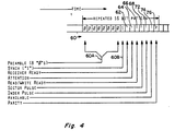
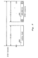
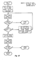
- the RTDS frame format is indicated in Fig. 4.
- the frame 60 comprises a preamble 60A of eight 0's followed by a sync bit 60B, which is a 1, six information bits 62-74 and a parity bit 76.
- Bit position 74 contains an "Available” bit, which is a logical signal from the drive to the controller indicating that the drive is in the "drive-available” state. It is asserted whenever the drive enters the "drive-available” state, remains asserted as long as the drive remains in that state, and is lowered when the drive leaves that state.
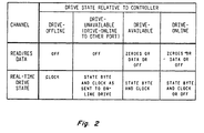
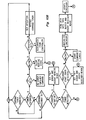
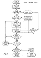
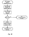
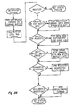
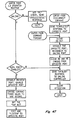
- the drive may be in any one of four states relative to the controller. These states differ in the manner in which the drive "listens” to commands and INIT signals through its port to the controller, the manner in which it deals its panel switches and the extent of controller visibility into and control over drive operation. Referring now to Fig. 5, the description of the drive states and how they are left and entered follows. There are four possible drive control states, designated “drive-offline” (state 82), “drive-unavailable” (state 84), “drive-available” (state 86), and “drive-online” (state 88).
- a drive leaves the "drive-available" state relative to a particular controller when any of the following occurs:
- a drive in the "drive-online” state relative to a particular controller is simultaneously in the "drive-unavailable” state to all other enabled controllers.
- a drive in the "drive-online” state does not alter its status in response to changes in the switch settings. Rather, when a drive detects such a switch change, it uses the Attention mechanism to report it to the controller. The controller determines how the drive will respond. The controller will either issue a direct command to effect the status change, or will issue a DISCONNECT command to make the drive enter the "drive-available” state, where it can effect the status change locally. Although the slight time delay is usually not noticeable to the operator who actuated the switch, the controller will delay action on the switch setting change until it has completed all preceding operations to the drive.
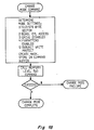
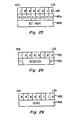
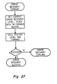
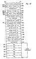
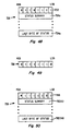
- Byte 510 contains the number of error recovery levels available in the drive.
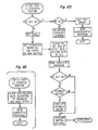
- Byte 620 contains seven bits signifying the number of replacement blocks (i.e., RBN's) per track and an eighth bit which is not germane to this discussion. As indicated, there is no present function assigned to byte 622; it is "reserved” for use when an extra byte is needed.
- the sizes of the data and header preambles are provided in bytes 624 and 626, respectively.
- Media type is specified in bytes 628-634; this indication may refer, for example, to a manufacturer's drive types.
- Bytes 636 and 638 contain an indication of the size of a copy of the format control table (FCT).
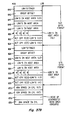
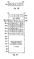
- byte 686 is a "reqeust” byte.
- the least significant bit “RU” in byte 686 indicates the status of the RUN/STOP switch; it may be zero if the switch is out and one if the switch is in, for example.
- the next lower bit, "PS”, indicates the status of the port switch; it may be zero if the switch is out, and one if the switch is in.
- the fourth bit, "EL”, indicates whether bytes 696-708 contain useful information; a "1" represents an affirmative statement.
- the fifth bit, "SR” indicates whether the spindle is ready; for example, if the bit is zero, the spindle is not ready and is not up to speed, and if it is one, the spindle is ready.
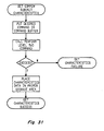
- Byte 694 contains a count of the number of retries, or a failure code.
Landscapes
- Engineering & Computer Science (AREA)
- Theoretical Computer Science (AREA)
- Physics & Mathematics (AREA)
- General Engineering & Computer Science (AREA)
- General Physics & Mathematics (AREA)
- Human Computer Interaction (AREA)
- Quality & Reliability (AREA)
- Computer Security & Cryptography (AREA)
- Communication Control (AREA)
- Information Transfer Systems (AREA)
- Retry When Errors Occur (AREA)
- Debugging And Monitoring (AREA)
- Signal Processing For Digital Recording And Reproducing (AREA)
- Selective Calling Equipment (AREA)
- Control Of Linear Motors (AREA)
- Control Of Vehicles With Linear Motors And Vehicles That Are Magnetically Levitated (AREA)
- Closures For Containers (AREA)
Claims (8)
Priority Applications (2)
| Application Number | Priority Date | Filing Date | Title |
|---|---|---|---|
| DE8282109213T DE3279059D1 (en) | 1981-10-05 | 1982-10-05 | Secondary storage facility employing serial communications between drive and controller |
| DE8585104748T DE3279688D1 (en) | 1981-10-05 | 1982-10-05 | Method and apparatus to determine the paths between mass storage devices and controllers |
Applications Claiming Priority (2)
| Application Number | Priority Date | Filing Date | Title |
|---|---|---|---|
| US30859381A | 1981-10-05 | 1981-10-05 | |
| US308593 | 1981-10-05 |
Related Child Applications (3)
| Application Number | Title | Priority Date | Filing Date |
|---|---|---|---|
| EP85104748.0 Division-Into | 1982-10-05 | ||
| EP85104763.9 Division-Into | 1982-10-05 | ||
| EP85104747.2 Division-Into | 1982-10-05 |
Publications (3)
| Publication Number | Publication Date |
|---|---|
| EP0077007A2 EP0077007A2 (fr) | 1983-04-20 |
| EP0077007A3 EP0077007A3 (en) | 1983-08-31 |
| EP0077007B1 true EP0077007B1 (fr) | 1988-09-21 |
Family
ID=23194581
Family Applications (4)
| Application Number | Title | Priority Date | Filing Date |
|---|---|---|---|
| EP85104747A Expired EP0163881B1 (fr) | 1981-10-05 | 1982-10-05 | Procédé et dispositif pour réparation d'erreurs dans un ordinateur éléctronique |
| EP82109213A Expired EP0077007B1 (fr) | 1981-10-05 | 1982-10-05 | Dispositif de mémoire supplémentaire utilisant des communications en série entre unités de commande et de contrôle |
| EP85104763A Expired EP0163883B1 (fr) | 1981-10-05 | 1982-10-05 | Dispositif de mémoire supplémentaire utilisant une communication en série entre les unités de sélection et de commande |
| EP85104748A Expired EP0163882B1 (fr) | 1981-10-05 | 1982-10-05 | Procédé et dispositif pour determiner les connexions entre des mémoires à grande capacité et des unités de commande |
Family Applications Before (1)
| Application Number | Title | Priority Date | Filing Date |
|---|---|---|---|
| EP85104747A Expired EP0163881B1 (fr) | 1981-10-05 | 1982-10-05 | Procédé et dispositif pour réparation d'erreurs dans un ordinateur éléctronique |
Family Applications After (2)
| Application Number | Title | Priority Date | Filing Date |
|---|---|---|---|
| EP85104763A Expired EP0163883B1 (fr) | 1981-10-05 | 1982-10-05 | Dispositif de mémoire supplémentaire utilisant une communication en série entre les unités de sélection et de commande |
| EP85104748A Expired EP0163882B1 (fr) | 1981-10-05 | 1982-10-05 | Procédé et dispositif pour determiner les connexions entre des mémoires à grande capacité et des unités de commande |
Country Status (6)
| Country | Link |
|---|---|
| EP (4) | EP0163881B1 (fr) |
| JP (7) | JPS58501695A (fr) |
| AU (4) | AU560352B2 (fr) |
| CA (1) | CA1187191A (fr) |
| DE (2) | DE3280165D1 (fr) |
| WO (1) | WO1983001321A1 (fr) |
Cited By (1)
| Publication number | Priority date | Publication date | Assignee | Title |
|---|---|---|---|---|
| US7526676B2 (en) | 2004-09-03 | 2009-04-28 | Avago Technologies General Ip (Singapore) Pte. Ltd. | Slave device having independent error recovery |
Families Citing this family (13)
| Publication number | Priority date | Publication date | Assignee | Title |
|---|---|---|---|---|
| US4612613A (en) * | 1983-05-16 | 1986-09-16 | Data General Corporation | Digital data bus system for connecting a controller and disk drives |
| JPS6097459A (ja) * | 1983-10-18 | 1985-05-31 | インタ−ナショナル ビジネス マシ−ンズ コ−ポレ−ション | デ−タ処理システム同期方法 |
| GB2237420B (en) * | 1989-10-20 | 1993-09-29 | Philips Electronic Associated | Computer terminal apparatus |
| DE69119076T2 (de) * | 1991-12-05 | 1996-11-21 | Ibm | Plattenlaufwerksynchronisierung |
| ES2127231T3 (es) * | 1992-06-29 | 1999-04-16 | Thomson Multimedia Sa | Bus serie de cuatro lineas. |
| US6014754A (en) * | 1995-06-29 | 2000-01-11 | International Business Machines Corporation | Signal recording and regenerating apparatus and error recovery processing execution sequence change method |
| JP4533520B2 (ja) * | 2000-10-06 | 2010-09-01 | 日本クラウンコルク株式会社 | 分別廃棄可能なプラスチックキャップ |
| JP4533528B2 (ja) * | 2000-12-06 | 2010-09-01 | 日本クラウンコルク株式会社 | 分別廃棄可能なプラスチックキャップ |
| JP4533530B2 (ja) * | 2000-12-20 | 2010-09-01 | 日本クラウンコルク株式会社 | 分別廃棄可能なプラスチックキャップ |
| JP4704592B2 (ja) * | 2001-04-12 | 2011-06-15 | 日本クラウンコルク株式会社 | プラスチックキャップ |
| JP3757858B2 (ja) | 2001-12-14 | 2006-03-22 | 船井電機株式会社 | ディスク再生装置 |
| US20140247513A1 (en) * | 2011-10-25 | 2014-09-04 | Michael S. Bunker | Environmental data record |
| US9240210B2 (en) | 2013-11-26 | 2016-01-19 | Seagate Technology Llc | Physical subsector error marking |
Citations (1)
| Publication number | Priority date | Publication date | Assignee | Title |
|---|---|---|---|---|
| DE2443176A1 (de) * | 1973-09-10 | 1975-03-13 | Computer Automation | Daten-speichereinrichtung mit automatischer adressenzuordnung und dafuer geeignetes adressierungsverfahren |
Family Cites Families (21)
| Publication number | Priority date | Publication date | Assignee | Title |
|---|---|---|---|---|
| US3336582A (en) * | 1964-09-01 | 1967-08-15 | Ibm | Interlocked communication system |
| JPS5440008B2 (fr) * | 1974-04-18 | 1979-12-01 | ||
| US3911400A (en) * | 1974-04-19 | 1975-10-07 | Digital Equipment Corp | Drive condition detecting circuit for secondary storage facilities in data processing systems |
| US4007448A (en) * | 1974-08-15 | 1977-02-08 | Digital Equipment Corporation | Drive for connection to multiple controllers in a digital data secondary storage facility |
| GB1492260A (en) * | 1974-10-29 | 1977-11-16 | Int Computers Ltd | Data processing systems |
| US4205370A (en) * | 1975-04-16 | 1980-05-27 | Honeywell Information Systems Inc. | Trace method and apparatus for use in a data processing system |
| US4053752A (en) * | 1975-09-15 | 1977-10-11 | International Business Machines Corporation | Error recovery and control in a mass storage system |
| US4044337A (en) * | 1975-12-23 | 1977-08-23 | International Business Machines Corporation | Instruction retry mechanism for a data processing system |
| US4228496A (en) * | 1976-09-07 | 1980-10-14 | Tandem Computers Incorporated | Multiprocessor system |
| JPS5362945A (en) * | 1976-11-17 | 1978-06-05 | Toshiba Corp | Disc address system |
| DE2659662C3 (de) * | 1976-12-30 | 1981-10-08 | Ibm Deutschland Gmbh, 7000 Stuttgart | Prioritätsstufengesteuerte Unterbrechungseinrichtung |
| JPS53127245A (en) * | 1977-04-13 | 1978-11-07 | Mitsubishi Electric Corp | Recovery system for electronic computer |
| US4130846A (en) * | 1977-04-27 | 1978-12-19 | Sperry Rand Corporation | Magnetic transducer |
| US4183084A (en) * | 1977-06-06 | 1980-01-08 | Digital Equipment Corporation | Secondary storage facility with serial transfer of control messages |
| US4144583A (en) * | 1977-06-06 | 1979-03-13 | Digital Equipment Corporation | Secondary storage facility with means for monitoring error conditions |
| US4101969A (en) * | 1977-06-06 | 1978-07-18 | Digital Equipment Corporation | Secondary storage facility with means for monitoring sector pulses |
| JPS5499538A (en) * | 1978-01-23 | 1979-08-06 | Nec Corp | Unit connection system |
| US4167779A (en) * | 1978-03-10 | 1979-09-11 | Digital Equipment Corporation | Diagnostic apparatus in a data processing system |
| US4207609A (en) * | 1978-05-08 | 1980-06-10 | International Business Machines Corporation | Method and means for path independent device reservation and reconnection in a multi-CPU and shared device access system |
| US4209809A (en) * | 1978-09-11 | 1980-06-24 | International Business Machines Corporation | Apparatus and method for record reorientation following error detection in a data storage subsystem |
| US4270205A (en) * | 1979-02-27 | 1981-05-26 | Phillips Petroleum Company | Serial line communication system |
-
1982
- 1982-09-24 JP JP57503066A patent/JPS58501695A/ja active Pending
- 1982-09-24 WO PCT/US1982/001212 patent/WO1983001321A1/fr not_active Ceased
- 1982-09-24 AU AU89913/82A patent/AU560352B2/en not_active Ceased
- 1982-10-05 DE DE8585104763T patent/DE3280165D1/de not_active Expired - Fee Related
- 1982-10-05 EP EP85104747A patent/EP0163881B1/fr not_active Expired
- 1982-10-05 EP EP82109213A patent/EP0077007B1/fr not_active Expired
- 1982-10-05 EP EP85104763A patent/EP0163883B1/fr not_active Expired
- 1982-10-05 EP EP85104748A patent/EP0163882B1/fr not_active Expired
- 1982-10-05 DE DE8585104747T patent/DE3280052D1/de not_active Expired - Fee Related
- 1982-10-05 CA CA000412823A patent/CA1187191A/fr not_active Expired
-
1987
- 1987-04-22 AU AU71873/87A patent/AU586744B2/en not_active Ceased
- 1987-04-22 AU AU71872/87A patent/AU586554B2/en not_active Ceased
- 1987-04-22 AU AU71874/87A patent/AU586555B2/en not_active Ceased
- 1987-05-29 JP JP62134807A patent/JPS63308636A/ja active Granted
- 1987-05-29 JP JP62134805A patent/JPS63308634A/ja active Granted
- 1987-05-29 JP JP62134806A patent/JPS63308635A/ja active Granted
-
1989
- 1989-08-14 JP JP1989095504U patent/JPH0284947U/ja active Pending
-
1991
- 1991-10-07 JP JP3259389A patent/JPH0573214A/ja active Pending
-
1995
- 1995-05-08 JP JP7109850A patent/JPH08301321A/ja active Pending
Patent Citations (1)
| Publication number | Priority date | Publication date | Assignee | Title |
|---|---|---|---|---|
| DE2443176A1 (de) * | 1973-09-10 | 1975-03-13 | Computer Automation | Daten-speichereinrichtung mit automatischer adressenzuordnung und dafuer geeignetes adressierungsverfahren |
Non-Patent Citations (1)
| Title |
|---|
| IBM PRAXIS Nr. 4, pages 13-15, 1964 * |
Cited By (1)
| Publication number | Priority date | Publication date | Assignee | Title |
|---|---|---|---|---|
| US7526676B2 (en) | 2004-09-03 | 2009-04-28 | Avago Technologies General Ip (Singapore) Pte. Ltd. | Slave device having independent error recovery |
Also Published As
| Publication number | Publication date |
|---|---|
| AU8991382A (en) | 1983-04-27 |
| AU7187287A (en) | 1987-08-13 |
| JPH0284947U (fr) | 1990-07-03 |
| AU560352B2 (en) | 1987-04-02 |
| JPH0450610B2 (fr) | 1992-08-14 |
| JPS63308635A (ja) | 1988-12-16 |
| JPS63308636A (ja) | 1988-12-16 |
| JPS58501695A (ja) | 1983-10-06 |
| CA1187191A (fr) | 1985-05-14 |
| EP0163882A1 (fr) | 1985-12-11 |
| EP0163882B1 (fr) | 1989-05-10 |
| AU7187487A (en) | 1987-08-13 |
| EP0077007A3 (en) | 1983-08-31 |
| JPH0573214A (ja) | 1993-03-26 |
| AU586554B2 (en) | 1989-07-13 |
| DE3280165D1 (de) | 1990-06-07 |
| WO1983001321A1 (fr) | 1983-04-14 |
| EP0163881B1 (fr) | 1989-12-06 |
| EP0077007A2 (fr) | 1983-04-20 |
| JPS63308634A (ja) | 1988-12-16 |
| EP0163883A1 (fr) | 1985-12-11 |
| AU586555B2 (en) | 1989-07-13 |
| EP0163881A1 (fr) | 1985-12-11 |
| DE3280052D1 (de) | 1990-01-11 |
| EP0163883B1 (fr) | 1990-05-02 |
| JPH0238963B2 (fr) | 1990-09-03 |
| JPH0450608B2 (fr) | 1992-08-14 |
| JPH08301321A (ja) | 1996-11-19 |
| AU7187387A (en) | 1987-08-13 |
| AU586744B2 (en) | 1989-07-20 |
Similar Documents
| Publication | Publication Date | Title |
|---|---|---|
| US4837675A (en) | Secondary storage facility empolying serial communications between drive and controller | |
| US4825406A (en) | Secondary storage facility employing serial communications between drive and controller | |
| US4811279A (en) | Secondary storage facility employing serial communications between drive and controller | |
| EP0077007B1 (fr) | Dispositif de mémoire supplémentaire utilisant des communications en série entre unités de commande et de contrôle | |
| US5758057A (en) | Multi-media storage system | |
| JP3181398B2 (ja) | アレイ型記録装置 | |
| KR100270751B1 (ko) | 기억장치서브시스템의자동구성방법및장치 | |
| EP0682314B1 (fr) | Système de stockage de données à disques redondant | |
| US4811278A (en) | Secondary storage facility employing serial communications between drive and controller | |
| US5313589A (en) | Low level device interface for direct access storage device including minimum functions and enabling high data rate performance | |
| AU637432B2 (en) | Multiple step data read apparatus | |
| KR100391740B1 (ko) | 재생 오류의 처리 방법 및 이를 이용한 디스크 장치 | |
| US5469546A (en) | Method for retrying recording information into a next logical block by sending sense data including address information to host computer and responding to command therefrom | |
| EP0669571B1 (fr) | Procédé et dispositif d'enregistrement/reproduction d'information | |
| US7047357B1 (en) | Virtualized striping controller | |
| JP2644218B2 (ja) | 磁気記録方法 | |
| JP3347362B2 (ja) | Scsiデータ転送方式 | |
| JPH0376059A (ja) | 磁気ディスク装置 | |
| JPS61133433A (ja) | 書換え不能なデ−タ記録媒体における不良セクタ代替え処理方式 | |
| JPH06131125A (ja) | ディスクアレイ装置 | |
| GB2307071A (en) | Multi-media storage system |
Legal Events
| Date | Code | Title | Description |
|---|---|---|---|
| PUAI | Public reference made under article 153(3) epc to a published international application that has entered the european phase |
Free format text: ORIGINAL CODE: 0009012 |
|
| AK | Designated contracting states |
Designated state(s): BE DE FR GB IT NL SE |
|
| PUAL | Search report despatched |
Free format text: ORIGINAL CODE: 0009013 |
|
| AK | Designated contracting states |
Designated state(s): BE DE FR GB IT NL SE |
|
| 17P | Request for examination filed |
Effective date: 19831130 |
|
| RAP1 | Party data changed (applicant data changed or rights of an application transferred) |
Owner name: DIGITAL EQUIPMENT CORPORATION |
|
| GRAA | (expected) grant |
Free format text: ORIGINAL CODE: 0009210 |
|
| AK | Designated contracting states |
Kind code of ref document: B1 Designated state(s): BE DE FR GB IT NL SE |
|
| ITF | It: translation for a ep patent filed | ||
| REF | Corresponds to: |
Ref document number: 3279059 Country of ref document: DE Date of ref document: 19881027 |
|
| ET | Fr: translation filed | ||
| PLBE | No opposition filed within time limit |
Free format text: ORIGINAL CODE: 0009261 |
|
| STAA | Information on the status of an ep patent application or granted ep patent |
Free format text: STATUS: NO OPPOSITION FILED WITHIN TIME LIMIT |
|
| 26N | No opposition filed | ||
| ITTA | It: last paid annual fee | ||
| EAL | Se: european patent in force in sweden |
Ref document number: 82109213.7 |
|
| PGFP | Annual fee paid to national office [announced via postgrant information from national office to epo] |
Ref country code: SE Payment date: 19980918 Year of fee payment: 17 |
|
| PGFP | Annual fee paid to national office [announced via postgrant information from national office to epo] |
Ref country code: NL Payment date: 19980921 Year of fee payment: 17 |
|
| PGFP | Annual fee paid to national office [announced via postgrant information from national office to epo] |
Ref country code: BE Payment date: 19981005 Year of fee payment: 17 |
|
| PG25 | Lapsed in a contracting state [announced via postgrant information from national office to epo] |
Ref country code: SE Free format text: THE PATENT HAS BEEN ANNULLED BY A DECISION OF A NATIONAL AUTHORITY Effective date: 19991030 |
|
| PG25 | Lapsed in a contracting state [announced via postgrant information from national office to epo] |
Ref country code: BE Free format text: LAPSE BECAUSE OF NON-PAYMENT OF DUE FEES Effective date: 19991031 |
|
| BERE | Be: lapsed |
Owner name: DIGITAL EQUIPMENT CORP. Effective date: 19991031 |
|
| PG25 | Lapsed in a contracting state [announced via postgrant information from national office to epo] |
Ref country code: NL Free format text: LAPSE BECAUSE OF NON-PAYMENT OF DUE FEES Effective date: 20000501 |
|
| EUG | Se: european patent has lapsed |
Ref document number: 82109213.7 |
|
| NLV4 | Nl: lapsed or anulled due to non-payment of the annual fee |
Effective date: 20000501 |
|
| REG | Reference to a national code |
Ref country code: GB Ref legal event code: 732E |
|
| PGFP | Annual fee paid to national office [announced via postgrant information from national office to epo] |
Ref country code: GB Payment date: 20011003 Year of fee payment: 20 |
|
| PGFP | Annual fee paid to national office [announced via postgrant information from national office to epo] |
Ref country code: FR Payment date: 20011010 Year of fee payment: 20 |
|
| PGFP | Annual fee paid to national office [announced via postgrant information from national office to epo] |
Ref country code: DE Payment date: 20011022 Year of fee payment: 20 |
|
| REG | Reference to a national code |
Ref country code: GB Ref legal event code: IF02 |
|
| PG25 | Lapsed in a contracting state [announced via postgrant information from national office to epo] |
Ref country code: GB Free format text: LAPSE BECAUSE OF EXPIRATION OF PROTECTION Effective date: 20021004 |
|
| REG | Reference to a national code |
Ref country code: GB Ref legal event code: PE20 Effective date: 20021004 |