EP0670251B1 - Dispositif de détection d'une variation d'inclinaison, destiné notamment aux véhicules automobiles - Google Patents
Dispositif de détection d'une variation d'inclinaison, destiné notamment aux véhicules automobiles Download PDFInfo
- Publication number
- EP0670251B1 EP0670251B1 EP95440009A EP95440009A EP0670251B1 EP 0670251 B1 EP0670251 B1 EP 0670251B1 EP 95440009 A EP95440009 A EP 95440009A EP 95440009 A EP95440009 A EP 95440009A EP 0670251 B1 EP0670251 B1 EP 0670251B1
- Authority
- EP
- European Patent Office
- Prior art keywords
- mobile arm
- vehicle
- marks
- axis
- electronic card
- Prior art date
- Legal status (The legal status is an assumption and is not a legal conclusion. Google has not performed a legal analysis and makes no representation as to the accuracy of the status listed.)
- Expired - Lifetime
Links
- XEEYBQQBJWHFJM-UHFFFAOYSA-N Iron Chemical group [Fe] XEEYBQQBJWHFJM-UHFFFAOYSA-N 0.000 claims abstract description 12
- 239000004020 conductor Substances 0.000 claims description 9
- 230000001960 triggered effect Effects 0.000 claims description 5
- 230000008859 change Effects 0.000 claims description 4
- 229910052742 iron Inorganic materials 0.000 claims description 4
- 230000003213 activating effect Effects 0.000 claims description 3
- 238000001514 detection method Methods 0.000 claims description 3
- 230000001939 inductive effect Effects 0.000 claims 1
- 210000003141 lower extremity Anatomy 0.000 claims 1
- 210000001364 upper extremity Anatomy 0.000 claims 1
- 238000006073 displacement reaction Methods 0.000 abstract description 4
- 239000003822 epoxy resin Substances 0.000 abstract description 2
- 229920000647 polyepoxide Polymers 0.000 abstract description 2
- 239000003990 capacitor Substances 0.000 description 7
- 230000000694 effects Effects 0.000 description 3
- 239000000463 material Substances 0.000 description 3
- 229920006395 saturated elastomer Polymers 0.000 description 3
- 230000035939 shock Effects 0.000 description 3
- 238000010586 diagram Methods 0.000 description 2
- 230000005484 gravity Effects 0.000 description 2
- 238000005259 measurement Methods 0.000 description 2
- 239000004033 plastic Substances 0.000 description 2
- 239000004593 Epoxy Substances 0.000 description 1
- 230000009471 action Effects 0.000 description 1
- 230000000903 blocking effect Effects 0.000 description 1
- 239000003638 chemical reducing agent Substances 0.000 description 1
- 238000013016 damping Methods 0.000 description 1
- 230000003100 immobilizing effect Effects 0.000 description 1
- 230000006698 induction Effects 0.000 description 1
- 239000007788 liquid Substances 0.000 description 1
- 239000003550 marker Substances 0.000 description 1
- 230000007246 mechanism Effects 0.000 description 1
- 239000002184 metal Substances 0.000 description 1
- 229910052751 metal Inorganic materials 0.000 description 1
- 230000004048 modification Effects 0.000 description 1
- 238000012986 modification Methods 0.000 description 1
- 239000012811 non-conductive material Substances 0.000 description 1
- 229920005989 resin Polymers 0.000 description 1
- 239000011347 resin Substances 0.000 description 1
- 239000007858 starting material Substances 0.000 description 1
Images

Classifications
-
- B—PERFORMING OPERATIONS; TRANSPORTING
- B60—VEHICLES IN GENERAL
- B60R—VEHICLES, VEHICLE FITTINGS, OR VEHICLE PARTS, NOT OTHERWISE PROVIDED FOR
- B60R25/00—Fittings or systems for preventing or indicating unauthorised use or theft of vehicles
- B60R25/10—Fittings or systems for preventing or indicating unauthorised use or theft of vehicles actuating a signalling device
- B60R25/1004—Alarm systems characterised by the type of sensor, e.g. current sensing means
- B60R25/1006—Mechanical sensors, e.g. pendulums
- B60R25/1007—Mechanical sensors, e.g. pendulums comprising associated circuitry
-
- G—PHYSICS
- G01—MEASURING; TESTING
- G01C—MEASURING DISTANCES, LEVELS OR BEARINGS; SURVEYING; NAVIGATION; GYROSCOPIC INSTRUMENTS; PHOTOGRAMMETRY OR VIDEOGRAMMETRY
- G01C9/00—Measuring inclination, e.g. by clinometers, by levels
- G01C9/12—Measuring inclination, e.g. by clinometers, by levels by using a single pendulum
Definitions
- the present invention relates to a device for detecting a variation in inclination, intended in particular motor vehicles.
- GB-A-2.120.882 describes a device comprising a sector supported by an axis, able to rotate around it in a vertical plane, by gravity, between the branches of a U-shaped base, openings being made at the base of said sector, while on one of the branches of the U are placed diodes electroluminescent, opposite which are arranged, on the other branch, photosensors detecting a difference between the received signals and the reference signals during a variation in the inclination of the sector.
- Document EP-A-0 261 443 relates to a inclinometer which detects an attempt to lifting a vehicle with a magnetic pendulum oscillating between two induction coils placed on a electrical circuit.
- Document US-A-4,703,315 describes a device tilt sensor which includes two plates of material non-conductive with raised conductive elements connected to an electronic card electrically connected to a battery, and between which is placed a pendulum also connected to the electronic card and to the battery, and able to establish with the conductive elements in relief a electrical contact allowing the electronic card to deduct or not the inclination of the vehicle and issue or not a signal activating an audible alarm.
- the object of the present invention is to remedy these disadvantages by proposing an electronic device to only trigger an alarm when the wheels front or rear of a vehicle are lifted off the ground.
- the device comprises a plate of non-conductive material on which are arranged conductive elements in relief connected to a card electronics electrically connected to the battery and ignition switch of the vehicle, and on which is further fixed a movable arm mounted in rotation around an axis perpendicular to the plane of said plate and connected to said electronic card and to the vehicle battery, said movable arm being able to establish with said elements conductors in relief an electrical contact allowing the electronic card to deduct from it or not the theft of the vehicle and whether to issue a signal activating an audible alarm.
- This device is essentially characterized in that the alarm is only triggered when the movement of the movable arm provides the electronic card with three pieces of information successive confirms a change of attitude of the vehicle linked to the detachment of its front or rear wheels.
- the plate used in the device according to the invention can be an angular sector or a disc, according to the embodiment chosen, and it is carried out in hard plastic such as resin epoxy.
- the mobile arm used in the device according to the invention can be a metal arm or an arm in plastic material provided with an element at its end protruding conductor of an enclosed conductive wire in the arm and connected to the electronic card and to the vehicle battery.
- the plate used is a sector fixedly mounted angular and conductive elements have the shape of raised marks arranged radially at the base of said sector and spaced regularly by forming sets of three successive landmarks a, b and c, the family landmarks a being connected together as well as the landmarks of families b and c, each family of landmarks being also connected to the connected electronic circuit of other goes to vehicle battery and ignition switch, while the axis of rotation of the movable arm is fixed to the top of the sector and oriented at around 45 ⁇ compared to the longitudinal axis of the vehicle, said movable arm having a length substantially equal to the radius of said sector and having a projecting element at its lower end able to touch the conductive elements in relief in establishing with them an electrical contact generating a electrical quantity which is processed by the card electronic, a displacement of said protruding element on three successive marks triggering an alarm.
- the alarm is triggered after the device has analyzed three information, a first initialization information of the system corresponding to the state of the stationary vehicle, what that its inclination with respect to the ground, when the engine is off; a second piece of information corresponding to a modification of the attitude of the vehicle; and a third information confirming this change of attitude in connection with the detachment of the front or rear wheels.
- the upper end of the movable arm is preferably secured to a soft iron hub of a certain mass which can pivot on a perpendicular axis said sector and opposite which is a solenoid, or a coil, surrounding a soft iron core, connected to the circuit electronic and intended to manage the movement of the mobile arm by locking it in position or releasing it when the coil is no longer supplied, which then makes the electromagnetic brake and allows the movable arm to resume its stable equilibrium position according to the law of gravity.
- the mobile arm of the device according to the invention can be advantageously immobilized when the car is used, which ensures the device longevity important.
- the conductive elements are spaced so that at an angle of about three degrees from at least the axis of rotation of the movable arm three successive marks a, b and c.
- the plate used is a disc which has two stops made of a material conductor, arranged a short distance from each other and between which the movable arm can move freely also made of a conductive material, the assembly formed by the movable arm and the stops constituting a switch for controlling a motor whose output axis is secured perpendicular to said disc and is intended to bring the movable arm, via the disc, in its position balance, stopping as soon as said movable arm is not no longer in contact with one of the two stops.
- Move angular of the motor axis corresponding to the return to the equilibrium position of the movable arm between the two stops induces a data representative of said displacement which, when it is greater than a certain setpoint, triggers an alarm.
- the electronic card is such that if the movable arm oscillates between the two stops, for example when the vehicle suffers a simple impact and not a significant effective uplift of an abduction, nothing happens.
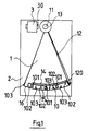
- the device according to the invention comprises an angular sector 1, for example in epoxy resin, at the bottom of which are engraved, at an angle of about 30 degrees, marks metallic reliefs 10 regularly spaced and arranged radially; an axis 11 fixed at the top of sector 1; an arm mobile or pendulum 12 connected to a voltage of 12 volts supplied by the vehicle battery, at the upper end which is arranged a soft iron hub 13 pivoting on the axis 11 while at its lower end part 120 is intended to touch, during a variation in angle of the pendulum, the metallic marks 10; and a card electronics 2 connected to pins 10, which form three sets of three marks 101, 102 and 103 arranged with so that at an angle of three degrees from the axis 11 there is at least a reference 101, a reference 102 and a item 103.
- All marks 101 are interconnected by a conductive track 14 connected on the other hand to an input 21 of the electronic card 2, the set of marks 102 are also interconnected by a conductive track 15 connected to an input 22 of the card 2, as well as the assembly marks 103, interconnected by a conductive track 16 connected to an input 23 of the card 2, the inputs 21, 22 and 23 being visible in FIG. 2.
- the soft iron hub 13 Opposite the soft iron hub 13 is placed a solenoid 3 connected to the board 2 and housing an iron core soft 30.
- the solenoid 3 When the solenoid 3 is energized the pendulum 12 is immobilized by the action of electromagnetic forces acting on the hub 13, which allows on the one hand to permanently monitor the movement of pendulum 12 and on the other hand to assure the device a lifetime important by immobilizing the pendulum 12 during use of the vehicle.
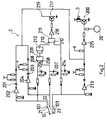
- the electronic card 2 includes in particular two NPN 200 and 217 transistors mounted as a common transmitter; five inverters 202, 204, 205, 213, 218; three NAND doors 209, 211, 212; five capacitors 201, 203, 206, 207, 214.
- the ignition key being in the on position appears a voltage of 12 volts in 20, putting the transistor 200 in saturated state, allowing coil 3 to be powered and therefore immobilize the pendulum 12.
- Capacity 201 being charged nothing happens at the level of the inverter 202, while the pendulum in its position at 101 keeps the capacitor 206 charged.
- the input of the inverter 204 is at logic level 1 associated with the value 12 volts, which has the effect of putting the output of the inverter 205 at level 1 for the duration of the charge of capacitor 203, transistor 200 is saturated and the coil 3 is energized, blocking pendulum 12 by effect electromagnetic for a certain time t during which capacity 207 is charged and gives a logical level 1 on the corresponding input 208 of the NAND logic gate 209, the other entrance 208 'of this door being also at the level logic 1, the output of gate 209 being at level zero this which has the effect of putting input 210 of the NAND gate 211 at level 1 via the inverter 212.
- the capacitors 206 and 207 remain charged for a time t 1 and when the capacitor 203 is charged the output of the inverter 205 goes to zero and releases the electromagnetic brake allowing the pendulum 12 to continue its race towards its position of stable equilibrium for establish contact with reference 103.
- the state of the inverter 213 then changes and its output goes to zero, the output of the inverter 205 goes back at level 1 immobilizes the pendulum 12, which remains in contact with the item 103.
- the capacitor 214 charges and entrance 210 'of door 211 goes to level 1 and as the other input 210 is maintained at level 1 by the load capacitors 206 and 207, the output state of the door 211 is at zero level and transistor 217 is at state saturated via the inverter 218 and behaves so as a closed switch which allows the setting vehicle alarm function, not shown.
- the attitude detector device of a vehicle according to the invention therefore chronologically deals with three information, managed by an electromagnetic brake, preventing said device from functioning as a simple shock detector.
- the device according to the invention comprises a disc 4 comprising in its part upper axis 50 around which is freely mounted rotation of a pendulum 5 likely to oscillate between two stops 51 and 52, of which only 51 is visible on the figure, the axis 50 and the pendulum 5 being produced in a electrically conductive material and the disc 4 which can besides oscillating around an axis perpendicular to its plane.
- the angular displacement of the disc 4 is carried out by means of a micro-motor 6 whose output axis 60, maintained between two bearings 61 and 62, is connected to a reducer 7 including the output axis 70, held between two bearings 71 and 72, is secured to the disc 4.
- the micro-motor 6 is controlled in operation, through an amplifier 8, by a microcontroller 90 belonging to a card electronic 9 and connected on the one hand to pendulum 5 by through the axis 50 and on the other hand at the two stops 51 and 52 and to the vehicle battery 24 through the starter.
- the assembly formed by the pendulum 5 and the stops 51 and 52 constitutes a switch which controls on the one hand the operation of the motor 6 when the pendulum 5 is in contact with either of the two stops 51 or 52 and on the other hand its stop in operation when the pendulum 5 is no longer in contact with the stops 51 or 52 and is in its equilibrium position.
- the supply circuit has been closed by the vehicle ignition key operates the engine 6 which brings, via the axis 60, the disc 4 in equilibrium position, if it is not already. When this position is reached the motor 6 stops and the device is then in standby state. If we tilt the vehicle, disc 4 follows the tilting movement so that observe a relative rotation of this disc 4 compared to the pendulum 5 in the direction of arrow B indicated in the figure 4, bringing the pendulum 5 into contact with the stop 51, which has to close the switch.
- the microcontroller 90 controls the micro-motor 6 in operation by making turn the axis 60 in direction A in order to bring back the pendulum 5 in its equilibrium position, the engine then being stopped.
- the computer of the microcontroller will then have determined the number of steps performed by axis 60 during rotation of disc 4 up to that pendulum 5 is in its equilibrium position, the number of steps being proportional to the angle of rotation of the disc 4 and therefore representative of the angular value corresponding to the inclination of the vehicle. If the angle measured is greater than a set angle, for example 3 °, the microcontroller controls the triggering of an alarm.
- the detection of a lateral uplift of a vehicle can be realized by arranging the plane of the disc parallel to a transverse plane of the vehicle and the detection of a longitudinal lift by placing the disc perpendicular to this plane.
Landscapes
- Engineering & Computer Science (AREA)
- Mechanical Engineering (AREA)
- Physics & Mathematics (AREA)
- General Physics & Mathematics (AREA)
- Radar, Positioning & Navigation (AREA)
- Remote Sensing (AREA)
- Burglar Alarm Systems (AREA)
- Vehicle Body Suspensions (AREA)
- Lighting Device Outwards From Vehicle And Optical Signal (AREA)
- Steering Controls (AREA)
- Control Of Stepping Motors (AREA)
Description
- la figure 1 représente une vue schématique du secteur angulaire selon un premier mode de réalisation du dispositif selon l'invention.
- la figure 2 représente le schéma de la carte électronique d'un dispositif selon l'invention.
- la figure 3 représente le schéma de fonctionnement du dispositif selon l'invention dans un deuxième mode de réalisation.
- la figure 4 représente une vue de face du disque selon ce deuxième mode de réalisation du dispositif selon l'invention.
Claims (4)
- Dispositif de détection d'une variation d'inclinaison, destiné notamment aux véhicules automobiles, comprenant une plaque (1, 4) en matériau non-conducteur sur laquelle sont disposés des éléments conducteurs (10, 51, 52) en relief reliés à une carte électronique (2) connectée électriquement à la batterie et au contact d'allumage du véhicule, et sur laquelle est fixé un bras mobile (12,5), monté en rotation autour d'un axe (11,50) perpendiculaire au plan de la dite plaque (1,4) et connecté à ladite carte électronique (2), ledit bras mobile (12, 5) étant apte à établir avec lesdits éléments conducteurs (10,51,52) un contact électrique qui permet à la carte électronique (2) d'en déduire ou non le vol du véhicule et d'émettre un signal activant une alarme sonore ; caractérisé en ce que l'alarme n'est déclenchée que lorsque le déplacement du bras mobile (12, 5) fournit à la carte électronique (2) trois informations successives confirmant un changement d'assiette du véhicule lié au décollement de ses roues avant ou arrière.
- Dispositif de détection selon la revendication 1 caractérisé en ce que la plaque est un secteur angulaire (1) monté fixement et en ce que les éléments conducteurs présentent la forme de repères en relief (10) disposés radialement à la base dudit secteur (1) et espacés régulièrement en formant des ensembles de trois repères successifs (101,102,103), les repères (101) étant connectés entre eux de même que les repères (102) et (103), chaque famille de repères étant également reliée à la carte électronique (2), tandis que l'axe de rotation (11) du bras mobile (12) est fixé au sommet du secteur (1) et orienté à environ 45° par rapport à l'axe longitudinal du véhicule, ledit bras mobile (12) ayant une longueur sensiblement égale au rayon dudit secteur (1) et possèdant à son extrémité inférieure un élément en saillie (120) apte à effleurer les éléments conducteurs en relief (10) en établissant un contact électrique générateur d'une grandeur électrique qui est traitée par la carte électronique (2), un déplacement dudit élément en saillie (120) sur trois repères successifs (101,102,103) déclenchant une alarme.
- Dispositif selon la revendication 2 caractérisé en ce que l'extrémité supérieure du bras mobile (12) est solidarisée à un moyeu de fer doux (13) d'une certaine masse pouvant pivoter sur l'axe (11) perpendiculaire au secteur (1) et en regard duquel se trouve un solénoïde (3) entourant un noyau de fer doux (30), relié au circuit électronique (2) et destiné à contrôler le déplacement du bras mobile (12).
- Dispositif selon la revendication 1 caractérisé en ce que la plaque mise en oeuvre est un disque (4) qui comporte deux butées (51,52) réalisées en un matériau conducteur, disposées à courte distance l'une de l'autre et entre lesquelles peut se déplacer librement un bras mobile (5) réalisé également en un matériau conducteur, l'ensemble formé par le bras mobile (5) et les butées (51,52) constituant un interrupteur de commande d'un moteur (6) dont l'axe de sortie (70) est solidarisé perpendiculairement audit disque (4) et est destiné à ramener le bras mobile (5), par l'intermédiaire du disque (4), dans sa position d'équilibre, en s'arrêtant dès que le bras mobile n'est plus en contact avec l'une des deux butées (51,52), le déplacement angulaire de l'axe moteur (70) correspondant au retour vers la position d'équilibre du bras mobile (5) entre les deux butées (51,52), induisant une donnée représentative dudit déplacement qui lorsqu'elle est supérieure à une certaine valeur de consigne entraíne le déclenchement d'une alarme.
Applications Claiming Priority (2)
| Application Number | Priority Date | Filing Date | Title |
|---|---|---|---|
| FR9402695A FR2716967B1 (fr) | 1994-03-04 | 1994-03-04 | Dispositif de détection d'une variation d'inclinaison, destiné notamment aux véhicules automobiles. |
| FR9402695 | 1994-03-04 |
Publications (2)
| Publication Number | Publication Date |
|---|---|
| EP0670251A1 EP0670251A1 (fr) | 1995-09-06 |
| EP0670251B1 true EP0670251B1 (fr) | 1998-12-23 |
Family
ID=9460827
Family Applications (1)
| Application Number | Title | Priority Date | Filing Date |
|---|---|---|---|
| EP95440009A Expired - Lifetime EP0670251B1 (fr) | 1994-03-04 | 1995-03-03 | Dispositif de détection d'une variation d'inclinaison, destiné notamment aux véhicules automobiles |
Country Status (4)
| Country | Link |
|---|---|
| EP (1) | EP0670251B1 (fr) |
| AT (1) | ATE174851T1 (fr) |
| DE (1) | DE69506752D1 (fr) |
| FR (1) | FR2716967B1 (fr) |
Families Citing this family (5)
| Publication number | Priority date | Publication date | Assignee | Title |
|---|---|---|---|---|
| DE19838233A1 (de) * | 1998-08-22 | 2000-02-24 | Opel Adam Ag | Diebstahlwarnanlage für Kraftfahrzeuge |
| JP3737963B2 (ja) * | 2001-11-16 | 2006-01-25 | 新キャタピラー三菱株式会社 | 建設機械 |
| DE10156425A1 (de) * | 2001-11-16 | 2003-05-28 | Delphi Tech Inc | Diebstahlalarmeinrichtung und Verfahren hierzu |
| GB2387006A (en) * | 2002-03-28 | 2003-10-01 | Motorola Inc | Motorcycle wireless communication system employing a tilt sensor to detect an emergency situation which is transmitted to a remote location |
| DE10323038B4 (de) | 2002-05-23 | 2018-07-26 | Marquardt Gmbh | Steuergerät für ein Kraftfahrzeug |
Family Cites Families (9)
| Publication number | Priority date | Publication date | Assignee | Title |
|---|---|---|---|---|
| DE2942551A1 (de) * | 1979-10-20 | 1981-04-30 | Robert Bosch Gmbh, 7000 Stuttgart | Alarmanlage, insbesondere fuer fahrzeuge |
| JPS58443A (ja) * | 1981-06-25 | 1983-01-05 | Adachi Jimusho:Kk | 自動車の盗難防止装置 |
| DE3208811C2 (de) * | 1982-03-11 | 1984-07-12 | Konrad 6831 Brühl Möbus | Neigungswinkelmeßgerät |
| JPS6184514A (ja) * | 1984-10-02 | 1986-04-30 | Omron Tateisi Electronics Co | 傾きセンサ |
| US4716534A (en) * | 1984-10-31 | 1987-12-29 | Baucom D Michael | Microprocessor based level and angle finder |
| JPS61211150A (ja) * | 1985-03-14 | 1986-09-19 | Matsushita Electric Works Ltd | 車両用盗難警報装置 |
| US4703315A (en) * | 1986-02-18 | 1987-10-27 | Bein David H | Level indicating device |
| DE8623044U1 (de) * | 1986-08-28 | 1986-10-09 | Händel, Helmut, 8039 Puchheim | Kraftfahrzeug mit Inklinometer |
| EP0259513B1 (fr) * | 1986-09-11 | 1989-12-13 | Schenck Auto-Service-Geräte GmbH | Procédé pour mesurer avec précision le carrosage et l'inclination du pivot de véhicules |
-
1994
- 1994-03-04 FR FR9402695A patent/FR2716967B1/fr not_active Expired - Fee Related
-
1995
- 1995-03-03 AT AT95440009T patent/ATE174851T1/de not_active IP Right Cessation
- 1995-03-03 DE DE69506752T patent/DE69506752D1/de not_active Expired - Lifetime
- 1995-03-03 EP EP95440009A patent/EP0670251B1/fr not_active Expired - Lifetime
Also Published As
| Publication number | Publication date |
|---|---|
| FR2716967A1 (fr) | 1995-09-08 |
| EP0670251A1 (fr) | 1995-09-06 |
| FR2716967B1 (fr) | 1996-06-28 |
| DE69506752D1 (de) | 1999-02-04 |
| ATE174851T1 (de) | 1999-01-15 |
Similar Documents
| Publication | Publication Date | Title |
|---|---|---|
| EP0099762B1 (fr) | Perfectionnements aux dispositifs de télécommande à code | |
| WO2005068280A1 (fr) | Systeme automatique de stockage de cycles | |
| FR2594778A1 (fr) | Dispositif antivol pour chariot a provisions | |
| FR2595398A1 (fr) | Ensemble de serrure et de cle electronique remplissant une fonction d'identification de cle | |
| EP0670251B1 (fr) | Dispositif de détection d'une variation d'inclinaison, destiné notamment aux véhicules automobiles | |
| WO2005001781A1 (fr) | Systeme automatique de stockage de cycles | |
| FR2777079A1 (fr) | Dispositif pour la detection de l'ouverture d'un compteur | |
| US3769472A (en) | Inertia sensor switch | |
| FR2654216A1 (fr) | ||
| FR2951431A1 (fr) | Dispositif et procede de verrouillage automatique d'une colonne de direction | |
| FR2833292A1 (fr) | Systeme de detection de presence d'un utilisateur notamment pour vehicule automobile | |
| EP1211649B1 (fr) | Poignée d'ouvrant de véhicule comprenant un capteur d'approche et un capteur tactile coopérant avec un système d'accés mains libres | |
| JPS6184514A (ja) | 傾きセンサ | |
| EP0678835B1 (fr) | Contrôleur de pièces métalliques, notamment de pièces de monnaie | |
| EP0640741B1 (fr) | Appareil pour le contrÔle de la traversée d'un passage soumis à autorisation | |
| FR2789632A1 (fr) | Dispositif de commande du demarrage d'un vehicule automobile et procede correspondant | |
| FR2605432A1 (fr) | Dispositif de securite antivol a verrouillage automatique pour cycles stationnant sur la voie publique | |
| EP1186472B1 (fr) | Dispositif pour la commande automatique d'extinction d'indicateurs de changement de direction sur véhicule automobile | |
| FR2462689A1 (fr) | Indicateur de devers | |
| EP1355284A1 (fr) | Système de réservation d'un emplacement de stationnement pour un véhicule | |
| EP1186471B1 (fr) | Dispositif pour la commande d'indicateurs de changement de direction sur véhicule automobile | |
| EP0969266A1 (fr) | Dispositif comprenant au moins deux roues coaxiales et des moyens de détection de leurs positions angulaires | |
| FR2605098A1 (fr) | Dispositif d'alarme detectant la modification d'assiette d'un corps | |
| FR2833387A1 (fr) | Procede de gestion et d'exploitation d'un ensemble d'organes de consigne d'un vehicule automobile, incluant l'emission d'un signal sonore | |
| FR2613301A2 (fr) | Systeme de protection pour vehicules automobiles en particulier a partir d'une centrale dont les cycles d'analyses sont bases sur le comportement humain |
Legal Events
| Date | Code | Title | Description |
|---|---|---|---|
| PUAI | Public reference made under article 153(3) epc to a published international application that has entered the european phase |
Free format text: ORIGINAL CODE: 0009012 |
|
| AK | Designated contracting states |
Kind code of ref document: A1 Designated state(s): AT BE CH DE DK ES FR GB GR IE IT LI LU MC NL PT SE |
|
| 17P | Request for examination filed |
Effective date: 19951106 |
|
| D17P | Request for examination filed (deleted) | ||
| 17Q | First examination report despatched |
Effective date: 19961211 |
|
| GRAG | Despatch of communication of intention to grant |
Free format text: ORIGINAL CODE: EPIDOS AGRA |
|
| GRAG | Despatch of communication of intention to grant |
Free format text: ORIGINAL CODE: EPIDOS AGRA |
|
| GRAH | Despatch of communication of intention to grant a patent |
Free format text: ORIGINAL CODE: EPIDOS IGRA |
|
| GRAH | Despatch of communication of intention to grant a patent |
Free format text: ORIGINAL CODE: EPIDOS IGRA |
|
| GRAA | (expected) grant |
Free format text: ORIGINAL CODE: 0009210 |
|
| AK | Designated contracting states |
Kind code of ref document: B1 Designated state(s): AT BE CH DE DK ES FR GB GR IE IT LI LU MC NL PT SE |
|
| PG25 | Lapsed in a contracting state [announced via postgrant information from national office to epo] |
Ref country code: NL Free format text: LAPSE BECAUSE OF FAILURE TO SUBMIT A TRANSLATION OF THE DESCRIPTION OR TO PAY THE FEE WITHIN THE PRESCRIBED TIME-LIMIT Effective date: 19981223 Ref country code: IT Free format text: LAPSE BECAUSE OF FAILURE TO SUBMIT A TRANSLATION OF THE DESCRIPTION OR TO PAY THE FEE WITHIN THE PRE;WARNING: LAPSES OF ITALIAN PATENTS WITH EFFECTIVE DATE BEFORE 2007 MAY HAVE OCCURRED AT ANY TIME BEFORE 2007. THE CORRECT EFFECTIVE DATE MAY BE DIFFERENT FROM THE ONE RECORDED.SCRIBED TIME-LIMIT Effective date: 19981223 Ref country code: GR Free format text: LAPSE BECAUSE OF NON-PAYMENT OF DUE FEES Effective date: 19981223 Ref country code: ES Free format text: THE PATENT HAS BEEN ANNULLED BY A DECISION OF A NATIONAL AUTHORITY Effective date: 19981223 Ref country code: AT Free format text: LAPSE BECAUSE OF FAILURE TO SUBMIT A TRANSLATION OF THE DESCRIPTION OR TO PAY THE FEE WITHIN THE PRESCRIBED TIME-LIMIT Effective date: 19981223 |
|
| REF | Corresponds to: |
Ref document number: 174851 Country of ref document: AT Date of ref document: 19990115 Kind code of ref document: T |
|
| REG | Reference to a national code |
Ref country code: CH Ref legal event code: EP |
|
| REF | Corresponds to: |
Ref document number: 69506752 Country of ref document: DE Date of ref document: 19990204 |
|
| REG | Reference to a national code |
Ref country code: IE Ref legal event code: FG4D Free format text: FRENCH |
|
| PG25 | Lapsed in a contracting state [announced via postgrant information from national office to epo] |
Ref country code: LU Free format text: LAPSE BECAUSE OF NON-PAYMENT OF DUE FEES Effective date: 19990303 |
|
| PG25 | Lapsed in a contracting state [announced via postgrant information from national office to epo] |
Ref country code: SE Free format text: LAPSE BECAUSE OF FAILURE TO SUBMIT A TRANSLATION OF THE DESCRIPTION OR TO PAY THE FEE WITHIN THE PRESCRIBED TIME-LIMIT Effective date: 19990323 Ref country code: PT Free format text: LAPSE BECAUSE OF FAILURE TO SUBMIT A TRANSLATION OF THE DESCRIPTION OR TO PAY THE FEE WITHIN THE PRESCRIBED TIME-LIMIT Effective date: 19990323 Ref country code: DK Free format text: LAPSE BECAUSE OF FAILURE TO SUBMIT A TRANSLATION OF THE DESCRIPTION OR TO PAY THE FEE WITHIN THE PRESCRIBED TIME-LIMIT Effective date: 19990323 |
|
| PG25 | Lapsed in a contracting state [announced via postgrant information from national office to epo] |
Ref country code: DE Free format text: LAPSE BECAUSE OF FAILURE TO SUBMIT A TRANSLATION OF THE DESCRIPTION OR TO PAY THE FEE WITHIN THE PRESCRIBED TIME-LIMIT Effective date: 19990324 |
|
| PG25 | Lapsed in a contracting state [announced via postgrant information from national office to epo] |
Ref country code: LI Free format text: LAPSE BECAUSE OF NON-PAYMENT OF DUE FEES Effective date: 19990331 Ref country code: CH Free format text: LAPSE BECAUSE OF NON-PAYMENT OF DUE FEES Effective date: 19990331 Ref country code: BE Free format text: LAPSE BECAUSE OF NON-PAYMENT OF DUE FEES Effective date: 19990331 |
|
| PGFP | Annual fee paid to national office [announced via postgrant information from national office to epo] |
Ref country code: FR Payment date: 19990331 Year of fee payment: 5 |
|
| GBT | Gb: translation of ep patent filed (gb section 77(6)(a)/1977) |
Effective date: 19990330 |
|
| NLV1 | Nl: lapsed or annulled due to failure to fulfill the requirements of art. 29p and 29m of the patents act | ||
| PG25 | Lapsed in a contracting state [announced via postgrant information from national office to epo] |
Ref country code: IE Free format text: LAPSE BECAUSE OF NON-PAYMENT OF DUE FEES Effective date: 19990820 |
|
| BERE | Be: lapsed |
Owner name: ELECTRO UNIVERS DIFFUSION Effective date: 19990331 |
|
| PG25 | Lapsed in a contracting state [announced via postgrant information from national office to epo] |
Ref country code: MC Free format text: LAPSE BECAUSE OF NON-PAYMENT OF DUE FEES Effective date: 19990930 |
|
| REG | Reference to a national code |
Ref country code: IE Ref legal event code: FD4D |
|
| PLBE | No opposition filed within time limit |
Free format text: ORIGINAL CODE: 0009261 |
|
| STAA | Information on the status of an ep patent application or granted ep patent |
Free format text: STATUS: NO OPPOSITION FILED WITHIN TIME LIMIT |
|
| REG | Reference to a national code |
Ref country code: CH Ref legal event code: PL |
|
| 26N | No opposition filed | ||
| PG25 | Lapsed in a contracting state [announced via postgrant information from national office to epo] |
Ref country code: FR Free format text: LAPSE BECAUSE OF NON-PAYMENT OF DUE FEES Effective date: 20000331 |
|
| PGFP | Annual fee paid to national office [announced via postgrant information from national office to epo] |
Ref country code: GB Payment date: 20000830 Year of fee payment: 6 |
|
| REG | Reference to a national code |
Ref country code: FR Ref legal event code: ST |
|
| REG | Reference to a national code |
Ref country code: FR Ref legal event code: RN |
|
| PG25 | Lapsed in a contracting state [announced via postgrant information from national office to epo] |
Ref country code: GB Free format text: LAPSE BECAUSE OF NON-PAYMENT OF DUE FEES Effective date: 20010303 |
|
| REG | Reference to a national code |
Ref country code: FR Ref legal event code: FC |
|
| GBPC | Gb: european patent ceased through non-payment of renewal fee |
Effective date: 20010303 |
|
| REG | Reference to a national code |
Ref country code: FR Ref legal event code: ST |