EP0672962A2 - Entwicklungsgerät - Google Patents
Entwicklungsgerät Download PDFInfo
- Publication number
- EP0672962A2 EP0672962A2 EP95103682A EP95103682A EP0672962A2 EP 0672962 A2 EP0672962 A2 EP 0672962A2 EP 95103682 A EP95103682 A EP 95103682A EP 95103682 A EP95103682 A EP 95103682A EP 0672962 A2 EP0672962 A2 EP 0672962A2
- Authority
- EP
- European Patent Office
- Prior art keywords
- toner
- agitation space
- agitation
- space
- developing unit
- Prior art date
- Legal status (The legal status is an assumption and is not a legal conclusion. Google has not performed a legal analysis and makes no representation as to the accuracy of the status listed.)
- Withdrawn
Links
Images


Classifications
-
- G—PHYSICS
- G03—PHOTOGRAPHY; CINEMATOGRAPHY; ANALOGOUS TECHNIQUES USING WAVES OTHER THAN OPTICAL WAVES; ELECTROGRAPHY; HOLOGRAPHY
- G03G—ELECTROGRAPHY; ELECTROPHOTOGRAPHY; MAGNETOGRAPHY
- G03G15/00—Apparatus for electrographic processes using a charge pattern
- G03G15/06—Apparatus for electrographic processes using a charge pattern for developing
- G03G15/08—Apparatus for electrographic processes using a charge pattern for developing using a solid developer, e.g. powder developer
-
- G—PHYSICS
- G03—PHOTOGRAPHY; CINEMATOGRAPHY; ANALOGOUS TECHNIQUES USING WAVES OTHER THAN OPTICAL WAVES; ELECTROGRAPHY; HOLOGRAPHY
- G03G—ELECTROGRAPHY; ELECTROPHOTOGRAPHY; MAGNETOGRAPHY
- G03G15/00—Apparatus for electrographic processes using a charge pattern
- G03G15/06—Apparatus for electrographic processes using a charge pattern for developing
- G03G15/08—Apparatus for electrographic processes using a charge pattern for developing using a solid developer, e.g. powder developer
- G03G15/0822—Arrangements for preparing, mixing, supplying or dispensing developer
-
- G—PHYSICS
- G03—PHOTOGRAPHY; CINEMATOGRAPHY; ANALOGOUS TECHNIQUES USING WAVES OTHER THAN OPTICAL WAVES; ELECTROGRAPHY; HOLOGRAPHY
- G03G—ELECTROGRAPHY; ELECTROPHOTOGRAPHY; MAGNETOGRAPHY
- G03G15/00—Apparatus for electrographic processes using a charge pattern
- G03G15/06—Apparatus for electrographic processes using a charge pattern for developing
- G03G15/08—Apparatus for electrographic processes using a charge pattern for developing using a solid developer, e.g. powder developer
- G03G15/0822—Arrangements for preparing, mixing, supplying or dispensing developer
- G03G15/0877—Arrangements for metering and dispensing developer from a developer cartridge into the development unit
-
- G—PHYSICS
- G03—PHOTOGRAPHY; CINEMATOGRAPHY; ANALOGOUS TECHNIQUES USING WAVES OTHER THAN OPTICAL WAVES; ELECTROGRAPHY; HOLOGRAPHY
- G03G—ELECTROGRAPHY; ELECTROPHOTOGRAPHY; MAGNETOGRAPHY
- G03G15/00—Apparatus for electrographic processes using a charge pattern
- G03G15/06—Apparatus for electrographic processes using a charge pattern for developing
- G03G15/08—Apparatus for electrographic processes using a charge pattern for developing using a solid developer, e.g. powder developer
- G03G15/0822—Arrangements for preparing, mixing, supplying or dispensing developer
- G03G15/0887—Arrangements for conveying and conditioning developer in the developing unit, e.g. agitating, removing impurities or humidity
- G03G15/0891—Arrangements for conveying and conditioning developer in the developing unit, e.g. agitating, removing impurities or humidity for conveying or circulating developer, e.g. augers
- G03G15/0893—Arrangements for conveying and conditioning developer in the developing unit, e.g. agitating, removing impurities or humidity for conveying or circulating developer, e.g. augers in a closed loop within the sump of the developing device
-
- G—PHYSICS
- G03—PHOTOGRAPHY; CINEMATOGRAPHY; ANALOGOUS TECHNIQUES USING WAVES OTHER THAN OPTICAL WAVES; ELECTROGRAPHY; HOLOGRAPHY
- G03G—ELECTROGRAPHY; ELECTROPHOTOGRAPHY; MAGNETOGRAPHY
- G03G2215/00—Apparatus for electrophotographic processes
- G03G2215/08—Details of powder developing device not concerning the development directly
- G03G2215/0802—Arrangements for agitating or circulating developer material
- G03G2215/0816—Agitator type
- G03G2215/0819—Agitator type two or more agitators
- G03G2215/0822—Agitator type two or more agitators with wall or blade between agitators
-
- G—PHYSICS
- G03—PHOTOGRAPHY; CINEMATOGRAPHY; ANALOGOUS TECHNIQUES USING WAVES OTHER THAN OPTICAL WAVES; ELECTROGRAPHY; HOLOGRAPHY
- G03G—ELECTROGRAPHY; ELECTROPHOTOGRAPHY; MAGNETOGRAPHY
- G03G2215/00—Apparatus for electrophotographic processes
- G03G2215/08—Details of powder developing device not concerning the development directly
- G03G2215/0802—Arrangements for agitating or circulating developer material
- G03G2215/0816—Agitator type
- G03G2215/0827—Augers
- G03G2215/083—Augers with two opposed pitches on one shaft
-
- Y—GENERAL TAGGING OF NEW TECHNOLOGICAL DEVELOPMENTS; GENERAL TAGGING OF CROSS-SECTIONAL TECHNOLOGIES SPANNING OVER SEVERAL SECTIONS OF THE IPC; TECHNICAL SUBJECTS COVERED BY FORMER USPC CROSS-REFERENCE ART COLLECTIONS [XRACs] AND DIGESTS
- Y10—TECHNICAL SUBJECTS COVERED BY FORMER USPC
- Y10S—TECHNICAL SUBJECTS COVERED BY FORMER USPC CROSS-REFERENCE ART COLLECTIONS [XRACs] AND DIGESTS
- Y10S222/00—Dispensing
- Y10S222/01—Xerography
Definitions
- the present invention relates to a developing unit comprising a developer container and a toner hopper for supplying the same with toner.
- a unit wherein a screw conveyer having a blade is adapted to agitate a developer material in a developer container is provided as a system for agitating the developer in the developer container of an image forming apparatus.
- the developer container of this type employs a so-called one-point drop system for feeding toner to the developer container.
- This system is arranged such that the screw conveyer is used to convey toner in a toner hopper while agitating it and the toner thus conveyed is fed to the developer container thereunder through a toner drop port provided at the toner hopper.
- the toner drop port generally comprises small holes which are defined in a predetermined position of a lower wall, as running downward or sideward.
- the toner hopper of the aforedescribed one-point drop system suffers the following two problems (i) and (ii).
- a developing unit comprises a developer container within which an agitation space for agitating developer therein is defined and a toner hopper disposed above the aforesaid agitation space in the aforesaid developer container, the aforesaid toner hopper comprising: a hopper housing containing toner therein, the inner part of which is separated from the agitation space by a lower wall, a toner drop port defined in the aforesaid lower wall and allowing the toner in the aforesaid hopper housing to fall into the aforesaid agitation space, and a partition wall which is formed on a surface of the aforesaid lower wall exposed to the agitation space as surrounding at least a part of the periphery of the aforesaid toner drop port, thus defining a non-agitation space within the aforesaid agitation space.
- the partition wall formed on the surface of the lower wall exposed to the agitation space surrounds at least a part of the periphery of the toner drop port so that the non-agitation space can be defined within the aforesaid agitation space. Toner is allowed to fall from the toner drop port smoothly in the agitation space through the aforesaid non-agitation space which is not affected by agitation of toner, and hence a constant supply of the toner is assured.
- a developing unit is applied to, for example, a copying machine operating as an image forming apparatus as shown in Fig. 2.
- the main body of a copying machine 1 includes therein (1) an optical system 3 for illuminating and scanning a document original placed on a transparent platen 2 and focusing image rays reflected from the illuminated document original onto a photoconductive drum 42, (2) an image processing portion 4 wherein an latent electrostatic image produced on the photoconductive drum 42 is developed into a toner image by a developing unit 41 and thereafter the image thus developed is transferred to a sheet of copy paper, and (3) a paper transport portion 5 which utilizes a paper take-up roll 51 having a semi-circular form in section to draw out the aforesaid paper from a paper feed tray 61 in a paper containing portion 6 and conveys the paper to a copy tray 56 in the main body of the copying machine via the image processing portion 4.
- the main body of the copying machine 1 comprises a lower unit 7 defined by a lower casing 71, and an upper unit 8 defined by an upper casing 81 as relatively turnablly supported with respect to the lower unit 7 around a predetermined pivotal axis m disposed at an end thereof.
- the main body of the copying machine 1 has a so-called clam-shell type structure wherein the upper unit 8 is relatively turnable with respect to the lower unit 7, to thereby allow the inner part thereof to be exposed.
- the optical system 3 illuminates a document original by means of a fluorescent lamp 39 having a reflector 38 which is secured to a first shift frame 3A, and focuses image rays reflected from the document original onto the photoconductive drum 42 sequentially thorough a first mirror 31 secured to the first shift frame 3A, a second mirror 32, a third mirror 33 and a lens 37 secured to a second shift frame 3B, a fourth mirror 34, a fifth mirror 35 and a sixth mirror 36 secured to a third shift frame 3C.
- the image processing portion 4 has a drum charge corona 43, the developing unit 41, an image transfer corona 44 and a cleaning unit 45 disposed around the photoconductive drum 42 in the order named.
- the image processing portion 4 is adapted such that a latent electrostatic image is produced by focusing image rays reflected from the document original on the outer peripheral surface of the uniformly charged photoconductive drum 42; thereafter the latent electrostatic image thus produced is developed into a toner image by the developing unit 41; the toner image so developed is transferred to a sheet of copy paper by the image transfer corona 44; and the residual toner is recovered by the cleaning unit 45.
- the paper transport portion 5 comprises the aforesaid paper take-up roll 51 for sequentially drawing out copy paper from the paper feed tray 61, a transport roller 52 for advancing the copy paper from a manual feed portion 60 or the paper feed tray 61, a main roller 53a and a driven roller 53b constituting resist means 53 against which the leading edge of the paper sent by the transport roller 52 is made to abut to thereby keep the paper temporarily in the stand-by condition, a fixing portion 54 for fixing the toner image transferred to the paper, and a pair of paper exit rollers 55.
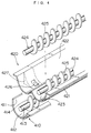
- the aforesaid developing unit 41 has a developer container 410 in which a developer is agitated, and a toner hopper 420 for feeding toner to an agitation space in the developer container 410.
- the developer container 410 has an agitation space 412 defined therein by the housing 411 thereof, and developer in the agitation space 412 is stirred by a screw conveyer 413 for developer agitation which includes a blade 414 wound thereon in a spiral form.
- a hopper housing 420A of the toner hopper 420 has a lower wall 421 substantially formed like W in section which partitions the agitation space thereunder.
- the gutter part 422 is closer to the photoconductive drum 42 than the gutter part 423.
- Each of the gutter parts 422, 423 includes therein a screw conveyer 424 for agitating and transporting toner which has a blade 425 wound thereon in a spiral form.
- a toner drop port 426 which is open obliquely downward, to allow toner in the toner hopper 420 to fall into the developer container 410.
- the gutter part 422 has a partition wall 427 which surrounds a part of the periphery of the toner drop port 426 and extends downward.
- the aforesaid partition wall 427 is defined on the lower surface of the aforesaid lower wall 421, surrounding the periphery of the aforesaid toner drop port 426 in cooperation with the lowermost part 421a of the aforesaid lower wall 421.
- the partition wall 427 comprises a pair of parts 427a, 427b orthogonal to the direction of the shaft of the aforesaid screw conveyer 424, and a part 427c parallel to the direction of the shaft of the aforesaid screw conveyer 424.
- the developing unit 41 is mounted in the upper unit 8 of the main body of the copying machine 1 while the aforementioned screw conveyer 424 is disposed in parallel to the pivotal axis m of the upper unit 8 of the main body of the copying machine 1, and hence the aforesaid parallel part 427c of the aforesaid partition wall 427 runs at a right angle to an inclination direction of the upper unit 8 when the main body of the copying machine 1 is opened.
- the parts 427a, 427b, 427c of the aforesaid partition wall 427 are spaced a certain distance from the circumference of the toner drop port 426 respectively.
- the edge of the aforesaid blade 425 and the lower end of the aforesaid partition wall 427 are spaced from each other by a predetermined distance of e. This prevents the developer conveyed by the screw conveyer 413 from unwantedly hitting against the partition wall 427, thereby ensuring that the agitation of the developer is not disturbed by the partition wall 427.
- the partition wall 427 formed on the lower surface of the lower wall 421 of the toner hopper 420 surrounds the periphery of the toner drop port 426, thus defining the aforesaid non-agitation space 430 within the aforesaid agitation space 412. Further, toner is allowed to fall from the toner drop port 426 smoothly in the agitation space 412 through the aforesaid non-agitation space 430 which is not affected by toner agitation, and hence a constant supply of the toner is assured.
- each of the parts 427a through 427c of the aforesaid partition wall 427 is a given distance away from the circumference of the toner drop port 426, so that the fall of toner from the toner drop port 426 is further facilitated.
- the aforesaid parallel part 427c of the aforesaid partition wall 427 is orthogonal to an inclination direction of the developing unit 41, which prevents the developer from flowing back from the agitation space 412 through the toner drop port into the toner hopper 420. As a result, a constant supply of the toner is assured.
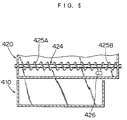
- FIG. 5 illustrates another embodiment of the present invention. With reference to the same figure, this embodiment differs from the above described embodiment in the following two points (i) and (ii).
- the toner hopper 420 has the following effects. More specifically, it is possible for the toner hopper 420 to have a larger space than the developer container 410, as expanded in the longitudinal direction thereof so that an amount of toner to be stored therein can be increased. Furthermore, the toner hopper 420 uses the aforesaid counterwound blade 425B to smoothly convey the toner contained in the part thereof protruding from the developer container 410, thereby avoiding that this part makes a dead space. Even if interference with other parts makes it difficult to spare a sufficient space for the toner hopper 420, the toner hopper 420 can secure a sufficient space only if it can extend itself in the longitudinal direction thereof. Accordingly this can enhance freedom of design.
Landscapes
- Physics & Mathematics (AREA)
- General Physics & Mathematics (AREA)
- Dry Development In Electrophotography (AREA)
Applications Claiming Priority (2)
| Application Number | Priority Date | Filing Date | Title |
|---|---|---|---|
| JP44223/94 | 1994-03-15 | ||
| JP6044223A JPH07253710A (ja) | 1994-03-15 | 1994-03-15 | トナーホッパ及びこれを含む現像装置 |
Publications (2)
| Publication Number | Publication Date |
|---|---|
| EP0672962A2 true EP0672962A2 (de) | 1995-09-20 |
| EP0672962A3 EP0672962A3 (de) | 1998-02-04 |
Family
ID=12685549
Family Applications (1)
| Application Number | Title | Priority Date | Filing Date |
|---|---|---|---|
| EP95103682A Withdrawn EP0672962A3 (de) | 1994-03-15 | 1995-03-14 | Entwicklungsgerät |
Country Status (6)
| Country | Link |
|---|---|
| US (1) | US5508792A (de) |
| EP (1) | EP0672962A3 (de) |
| JP (1) | JPH07253710A (de) |
| KR (1) | KR950033726A (de) |
| CN (1) | CN1119752A (de) |
| TW (1) | TW346203U (de) |
Cited By (2)
| Publication number | Priority date | Publication date | Assignee | Title |
|---|---|---|---|---|
| EP0777158A1 (de) * | 1995-11-29 | 1997-06-04 | Mita Industrial Co. Ltd. | Entwicklungsgerät |
| EP0816938A3 (de) * | 1996-07-04 | 1999-04-07 | Mita Industrial Co. Ltd. | Transportvorrichtung und Tonerkartusche mit Transportvorrichtung |
Families Citing this family (7)
| Publication number | Priority date | Publication date | Assignee | Title |
|---|---|---|---|---|
| JP3326590B2 (ja) * | 1997-01-14 | 2002-09-24 | 京セラミタ株式会社 | 画像形成機のトナー補給装置 |
| EP1233311B1 (de) * | 2001-02-19 | 2012-08-29 | Canon Kabushiki Kaisha | Tonerzufuhrbehälter |
| US6973281B2 (en) * | 2002-04-26 | 2005-12-06 | Canon Kabushiki Kaisha | Developing apparatus with two developing chamber-rotatable member pairs |
| JP4603418B2 (ja) * | 2005-05-18 | 2010-12-22 | シャープ株式会社 | 現像装置 |
| JP2007298908A (ja) * | 2006-05-08 | 2007-11-15 | Fuji Xerox Co Ltd | プロセスカートリッジ、画像形成装置及びプロセスカートリッジの組立て方法 |
| JP4433016B2 (ja) * | 2007-08-17 | 2010-03-17 | コニカミノルタビジネステクノロジーズ株式会社 | 現像装置、現像ユニットおよび画像形成装置 |
| KR101529490B1 (ko) * | 2008-10-24 | 2015-06-30 | 삼성전자 주식회사 | 화상형성장치의 현상기 |
Family Cites Families (9)
| Publication number | Priority date | Publication date | Assignee | Title |
|---|---|---|---|---|
| JPS55161262A (en) * | 1979-06-04 | 1980-12-15 | Toray Ind Inc | Developing device |
| JPS57211177A (en) * | 1981-06-23 | 1982-12-24 | Hitachi Metals Ltd | Picture reproducing device |
| US4478512A (en) * | 1983-05-11 | 1984-10-23 | Xerox Corporation | Toner cartridge for use in an electrophotographic printing machine |
| JPS6087364A (ja) * | 1983-10-19 | 1985-05-17 | Toshiba Corp | 現像装置 |
| JPS60230168A (ja) * | 1984-04-27 | 1985-11-15 | Toshiba Corp | 像形成装置 |
| US5153646A (en) * | 1984-04-27 | 1992-10-06 | Kabushiki Kaisha Toshiba | Image forming apparatus with removable developing means |
| JPH01142762A (ja) * | 1987-11-30 | 1989-06-05 | Toshiba Corp | 現像剤補給装置 |
| US5172168A (en) * | 1990-09-05 | 1992-12-15 | Matsushita Electric Industrial Co., Ltd. | Electrophotographic system haivng a developing device with a plurality of toner feeders |
| JPH05197281A (ja) * | 1992-01-21 | 1993-08-06 | Minolta Camera Co Ltd | 画像形成装置 |
-
1994
- 1994-03-15 JP JP6044223A patent/JPH07253710A/ja active Pending
-
1995
- 1995-03-06 US US08/398,785 patent/US5508792A/en not_active Expired - Lifetime
- 1995-03-13 KR KR1019950005078A patent/KR950033726A/ko not_active Withdrawn
- 1995-03-14 EP EP95103682A patent/EP0672962A3/de not_active Withdrawn
- 1995-03-14 TW TW086200841U patent/TW346203U/zh unknown
- 1995-03-15 CN CN95102451A patent/CN1119752A/zh active Pending
Cited By (2)
| Publication number | Priority date | Publication date | Assignee | Title |
|---|---|---|---|---|
| EP0777158A1 (de) * | 1995-11-29 | 1997-06-04 | Mita Industrial Co. Ltd. | Entwicklungsgerät |
| EP0816938A3 (de) * | 1996-07-04 | 1999-04-07 | Mita Industrial Co. Ltd. | Transportvorrichtung und Tonerkartusche mit Transportvorrichtung |
Also Published As
| Publication number | Publication date |
|---|---|
| KR950033726A (ko) | 1995-12-26 |
| EP0672962A3 (de) | 1998-02-04 |
| US5508792A (en) | 1996-04-16 |
| JPH07253710A (ja) | 1995-10-03 |
| CN1119752A (zh) | 1996-04-03 |
| TW346203U (en) | 1998-11-21 |
Similar Documents
| Publication | Publication Date | Title |
|---|---|---|
| EP0817459B1 (de) | Elektrofotografisches Bilderzeugungsgerät mit lösbar montierbarer Dokumentlesevorrichtung | |
| US9426318B2 (en) | Image reader unit and image forming apparatus including same | |
| EP0497602A2 (de) | Kassette mit Papiertransport | |
| US5508792A (en) | Developing unit including a partition wall defining a non-agitation space in a developer container | |
| JPH11157726A (ja) | 画像形成装置 | |
| JPH09325548A (ja) | 画像形成装置 | |
| JP2784679B2 (ja) | 画像形成装置 | |
| JP3227394B2 (ja) | トナー補給装置 | |
| JPH05249828A (ja) | 画像形成装置の現像器 | |
| JPH09325549A (ja) | 画像形成装置 | |
| JPH04198966A (ja) | 画像形成装置 | |
| JP2005162476A (ja) | 用紙の搬送路切換構造 | |
| JP2001125443A (ja) | 画像形成装置 | |
| JPH05249824A (ja) | 現像剤撹拌装置 | |
| JPH10319694A (ja) | 画像形成装置 | |
| JPH06138744A (ja) | カラー画像形成装置 | |
| US20250237974A1 (en) | Image forming apparatus | |
| US12554213B2 (en) | Developing device including toner concentration sensor that detects toner concentration in developer and image forming apparatus | |
| JP2599112B2 (ja) | プリンタ装置 | |
| JP2006126635A (ja) | カラー画像形成装置 | |
| JPH05224530A (ja) | トナー補給装置 | |
| JP3392429B2 (ja) | 複写機及びスキャナ・画像形成装置 | |
| JP3687588B2 (ja) | 画像形成装置 | |
| US5842083A (en) | Electrostatic copying machine | |
| JPS6385660A (ja) | 電子複写機のトナ−カ−トリツジ |
Legal Events
| Date | Code | Title | Description |
|---|---|---|---|
| PUAI | Public reference made under article 153(3) epc to a published international application that has entered the european phase |
Free format text: ORIGINAL CODE: 0009012 |
|
| AK | Designated contracting states |
Kind code of ref document: A2 Designated state(s): DE FR GB IT |
|
| PUAL | Search report despatched |
Free format text: ORIGINAL CODE: 0009013 |
|
| AK | Designated contracting states |
Kind code of ref document: A3 Designated state(s): DE FR GB IT |
|
| 17P | Request for examination filed |
Effective date: 19980715 |
|
| 17Q | First examination report despatched |
Effective date: 19980824 |
|
| STAA | Information on the status of an ep patent application or granted ep patent |
Free format text: STATUS: THE APPLICATION IS DEEMED TO BE WITHDRAWN |
|
| 18D | Application deemed to be withdrawn |
Effective date: 19990104 |