EP0673025B1 - Milieu d'enregistrement magnéto-optique et procédé pour utiliser celui-ci - Google Patents
Milieu d'enregistrement magnéto-optique et procédé pour utiliser celui-ci Download PDFInfo
- Publication number
- EP0673025B1 EP0673025B1 EP95101483A EP95101483A EP0673025B1 EP 0673025 B1 EP0673025 B1 EP 0673025B1 EP 95101483 A EP95101483 A EP 95101483A EP 95101483 A EP95101483 A EP 95101483A EP 0673025 B1 EP0673025 B1 EP 0673025B1
- Authority
- EP
- European Patent Office
- Prior art keywords
- layer
- magnetic
- recording
- reproducing
- magneto
- Prior art date
- Legal status (The legal status is an assumption and is not a legal conclusion. Google has not performed a legal analysis and makes no representation as to the accuracy of the status listed.)
- Expired - Lifetime
Links
Images



Classifications
-
- G—PHYSICS
- G11—INFORMATION STORAGE
- G11B—INFORMATION STORAGE BASED ON RELATIVE MOVEMENT BETWEEN RECORD CARRIER AND TRANSDUCER
- G11B11/00—Recording on or reproducing from the same record carrier wherein for these two operations the methods are covered by different main groups of groups G11B3/00 - G11B7/00 or by different subgroups of group G11B9/00; Record carriers therefor
- G11B11/10—Recording on or reproducing from the same record carrier wherein for these two operations the methods are covered by different main groups of groups G11B3/00 - G11B7/00 or by different subgroups of group G11B9/00; Record carriers therefor using recording by magnetic means or other means for magnetisation or demagnetisation of a record carrier, e.g. light induced spin magnetisation; Demagnetisation by thermal or stress means in the presence or not of an orienting magnetic field
- G11B11/105—Recording on or reproducing from the same record carrier wherein for these two operations the methods are covered by different main groups of groups G11B3/00 - G11B7/00 or by different subgroups of group G11B9/00; Record carriers therefor using recording by magnetic means or other means for magnetisation or demagnetisation of a record carrier, e.g. light induced spin magnetisation; Demagnetisation by thermal or stress means in the presence or not of an orienting magnetic field using a beam of light or a magnetic field for recording by change of magnetisation and a beam of light for reproducing, i.e. magneto-optical, e.g. light-induced thermomagnetic recording, spin magnetisation recording, Kerr or Faraday effect reproducing
- G11B11/10595—Control of operating function
- G11B11/10597—Adaptations for transducing various formats on the same or different carriers
-
- G—PHYSICS
- G11—INFORMATION STORAGE
- G11B—INFORMATION STORAGE BASED ON RELATIVE MOVEMENT BETWEEN RECORD CARRIER AND TRANSDUCER
- G11B11/00—Recording on or reproducing from the same record carrier wherein for these two operations the methods are covered by different main groups of groups G11B3/00 - G11B7/00 or by different subgroups of group G11B9/00; Record carriers therefor
- G11B11/10—Recording on or reproducing from the same record carrier wherein for these two operations the methods are covered by different main groups of groups G11B3/00 - G11B7/00 or by different subgroups of group G11B9/00; Record carriers therefor using recording by magnetic means or other means for magnetisation or demagnetisation of a record carrier, e.g. light induced spin magnetisation; Demagnetisation by thermal or stress means in the presence or not of an orienting magnetic field
- G11B11/105—Recording on or reproducing from the same record carrier wherein for these two operations the methods are covered by different main groups of groups G11B3/00 - G11B7/00 or by different subgroups of group G11B9/00; Record carriers therefor using recording by magnetic means or other means for magnetisation or demagnetisation of a record carrier, e.g. light induced spin magnetisation; Demagnetisation by thermal or stress means in the presence or not of an orienting magnetic field using a beam of light or a magnetic field for recording by change of magnetisation and a beam of light for reproducing, i.e. magneto-optical, e.g. light-induced thermomagnetic recording, spin magnetisation recording, Kerr or Faraday effect reproducing
- G11B11/10502—Recording on or reproducing from the same record carrier wherein for these two operations the methods are covered by different main groups of groups G11B3/00 - G11B7/00 or by different subgroups of group G11B9/00; Record carriers therefor using recording by magnetic means or other means for magnetisation or demagnetisation of a record carrier, e.g. light induced spin magnetisation; Demagnetisation by thermal or stress means in the presence or not of an orienting magnetic field using a beam of light or a magnetic field for recording by change of magnetisation and a beam of light for reproducing, i.e. magneto-optical, e.g. light-induced thermomagnetic recording, spin magnetisation recording, Kerr or Faraday effect reproducing characterised by the transducing operation to be executed
- G11B11/10504—Recording
- G11B11/10506—Recording by modulating only the light beam of the transducer
-
- G—PHYSICS
- G11—INFORMATION STORAGE
- G11B—INFORMATION STORAGE BASED ON RELATIVE MOVEMENT BETWEEN RECORD CARRIER AND TRANSDUCER
- G11B11/00—Recording on or reproducing from the same record carrier wherein for these two operations the methods are covered by different main groups of groups G11B3/00 - G11B7/00 or by different subgroups of group G11B9/00; Record carriers therefor
- G11B11/10—Recording on or reproducing from the same record carrier wherein for these two operations the methods are covered by different main groups of groups G11B3/00 - G11B7/00 or by different subgroups of group G11B9/00; Record carriers therefor using recording by magnetic means or other means for magnetisation or demagnetisation of a record carrier, e.g. light induced spin magnetisation; Demagnetisation by thermal or stress means in the presence or not of an orienting magnetic field
- G11B11/105—Recording on or reproducing from the same record carrier wherein for these two operations the methods are covered by different main groups of groups G11B3/00 - G11B7/00 or by different subgroups of group G11B9/00; Record carriers therefor using recording by magnetic means or other means for magnetisation or demagnetisation of a record carrier, e.g. light induced spin magnetisation; Demagnetisation by thermal or stress means in the presence or not of an orienting magnetic field using a beam of light or a magnetic field for recording by change of magnetisation and a beam of light for reproducing, i.e. magneto-optical, e.g. light-induced thermomagnetic recording, spin magnetisation recording, Kerr or Faraday effect reproducing
- G11B11/10502—Recording on or reproducing from the same record carrier wherein for these two operations the methods are covered by different main groups of groups G11B3/00 - G11B7/00 or by different subgroups of group G11B9/00; Record carriers therefor using recording by magnetic means or other means for magnetisation or demagnetisation of a record carrier, e.g. light induced spin magnetisation; Demagnetisation by thermal or stress means in the presence or not of an orienting magnetic field using a beam of light or a magnetic field for recording by change of magnetisation and a beam of light for reproducing, i.e. magneto-optical, e.g. light-induced thermomagnetic recording, spin magnetisation recording, Kerr or Faraday effect reproducing characterised by the transducing operation to be executed
- G11B11/10515—Reproducing
-
- G—PHYSICS
- G11—INFORMATION STORAGE
- G11B—INFORMATION STORAGE BASED ON RELATIVE MOVEMENT BETWEEN RECORD CARRIER AND TRANSDUCER
- G11B11/00—Recording on or reproducing from the same record carrier wherein for these two operations the methods are covered by different main groups of groups G11B3/00 - G11B7/00 or by different subgroups of group G11B9/00; Record carriers therefor
- G11B11/10—Recording on or reproducing from the same record carrier wherein for these two operations the methods are covered by different main groups of groups G11B3/00 - G11B7/00 or by different subgroups of group G11B9/00; Record carriers therefor using recording by magnetic means or other means for magnetisation or demagnetisation of a record carrier, e.g. light induced spin magnetisation; Demagnetisation by thermal or stress means in the presence or not of an orienting magnetic field
- G11B11/105—Recording on or reproducing from the same record carrier wherein for these two operations the methods are covered by different main groups of groups G11B3/00 - G11B7/00 or by different subgroups of group G11B9/00; Record carriers therefor using recording by magnetic means or other means for magnetisation or demagnetisation of a record carrier, e.g. light induced spin magnetisation; Demagnetisation by thermal or stress means in the presence or not of an orienting magnetic field using a beam of light or a magnetic field for recording by change of magnetisation and a beam of light for reproducing, i.e. magneto-optical, e.g. light-induced thermomagnetic recording, spin magnetisation recording, Kerr or Faraday effect reproducing
- G11B11/10582—Record carriers characterised by the selection of the material or by the structure or form
- G11B11/10584—Record carriers characterised by the selection of the material or by the structure or form characterised by the form, e.g. comprising mechanical protection elements
-
- G—PHYSICS
- G11—INFORMATION STORAGE
- G11B—INFORMATION STORAGE BASED ON RELATIVE MOVEMENT BETWEEN RECORD CARRIER AND TRANSDUCER
- G11B11/00—Recording on or reproducing from the same record carrier wherein for these two operations the methods are covered by different main groups of groups G11B3/00 - G11B7/00 or by different subgroups of group G11B9/00; Record carriers therefor
- G11B11/10—Recording on or reproducing from the same record carrier wherein for these two operations the methods are covered by different main groups of groups G11B3/00 - G11B7/00 or by different subgroups of group G11B9/00; Record carriers therefor using recording by magnetic means or other means for magnetisation or demagnetisation of a record carrier, e.g. light induced spin magnetisation; Demagnetisation by thermal or stress means in the presence or not of an orienting magnetic field
- G11B11/105—Recording on or reproducing from the same record carrier wherein for these two operations the methods are covered by different main groups of groups G11B3/00 - G11B7/00 or by different subgroups of group G11B9/00; Record carriers therefor using recording by magnetic means or other means for magnetisation or demagnetisation of a record carrier, e.g. light induced spin magnetisation; Demagnetisation by thermal or stress means in the presence or not of an orienting magnetic field using a beam of light or a magnetic field for recording by change of magnetisation and a beam of light for reproducing, i.e. magneto-optical, e.g. light-induced thermomagnetic recording, spin magnetisation recording, Kerr or Faraday effect reproducing
- G11B11/10582—Record carriers characterised by the selection of the material or by the structure or form
- G11B11/10586—Record carriers characterised by the selection of the material or by the structure or form characterised by the selection of the material
-
- G—PHYSICS
- G11—INFORMATION STORAGE
- G11B—INFORMATION STORAGE BASED ON RELATIVE MOVEMENT BETWEEN RECORD CARRIER AND TRANSDUCER
- G11B19/00—Driving, starting, stopping record carriers not specifically of filamentary or web form, or of supports therefor; Control thereof; Control of operating function ; Driving both disc and head
- G11B19/20—Driving; Starting; Stopping; Control thereof
- G11B19/26—Speed-changing arrangements; Reversing arrangements; Drive-transfer means therefor
-
- G—PHYSICS
- G11—INFORMATION STORAGE
- G11B—INFORMATION STORAGE BASED ON RELATIVE MOVEMENT BETWEEN RECORD CARRIER AND TRANSDUCER
- G11B19/00—Driving, starting, stopping record carriers not specifically of filamentary or web form, or of supports therefor; Control thereof; Control of operating function ; Driving both disc and head
- G11B19/20—Driving; Starting; Stopping; Control thereof
- G11B19/28—Speed controlling, regulating, or indicating
-
- Y—GENERAL TAGGING OF NEW TECHNOLOGICAL DEVELOPMENTS; GENERAL TAGGING OF CROSS-SECTIONAL TECHNOLOGIES SPANNING OVER SEVERAL SECTIONS OF THE IPC; TECHNICAL SUBJECTS COVERED BY FORMER USPC CROSS-REFERENCE ART COLLECTIONS [XRACs] AND DIGESTS
- Y10—TECHNICAL SUBJECTS COVERED BY FORMER USPC
- Y10S—TECHNICAL SUBJECTS COVERED BY FORMER USPC CROSS-REFERENCE ART COLLECTIONS [XRACs] AND DIGESTS
- Y10S428/00—Stock material or miscellaneous articles
- Y10S428/90—Magnetic feature
Definitions
- the present invention relates generally to a magneto-optical recording medium and, more particularly, to a recording medium having both a RAM part recordable, reproducible and erasable by a recording/reproducing apparatus of a user and a ROM part reproducible but not rewritable by such an apparatus.
- US-A-3,956,769 discloses a magnetic recording system employing a magnetic recording medium having a relatively high coercitivity first recording layer with servo tracks recorded therein, and a second layer of lower coercitivity in which data may be recorded.
- a magnetic recording medium having a relatively high coercitivity first recording layer with servo tracks recorded therein, and a second layer of lower coercitivity in which data may be recorded.
- the two layers are completely independent from each other.
- this known recording medium it is always possible to use any area of the second layer as a RAM even if data is recorded in the first layer underneath it.
- EP-A-0 575 934 the use of a magneto-optical medium as a ROM/RAM is known, whereby the ROM data are stored in pits and the RAM data are stored in magnetic areas.
- a magneto-optical medium having laminated magnetic layers with different recording sensitivity, e.g. based on different coercitivity or Curie temperature.
- this known magneto-optical medium forming a ROM area and a RAM area is not possible in view of a lack in the magnetic bonding between the laminated layers.
- a CD-ROM is disadvantageous because of its insufficient degree of freedom in practical use due to slow reproduction and nonexistence of a recordable/erasable user area.
- a partial ROM which is a magneto-optical recording medium having both a reproduction-only area and recording/reproduction area.
- indented pits ROM pits
- provision of read-only software is rendered possible by the technique substantially equal to that for the CD-ROM.
- a substrate of an optical disk is produced by a method of injection-molding a resinous material
- a metallic stamper is first required to serve as a master in manufacture of a conventional partial ROM medium. Therefore, in providing new software, it is necessary to produce a stamper where new information has been recorded. Since highly advanced apparatus and techniques are required for producing such a stamper, any software provider having none of adequate equipment needs to request a third party for production of a stamper and a substrate as well when providing a conventional partial ROM medium. And there exists another disadvantage that, in case any inconvenience is found in a stage posterior to start of mass production, it has been impossible heretofore to debug such inconvenience in the conventional partial ROM medium.
- an ordinary magneto-optical disk medium see EP-A-0 575 934) a plurality of grooves and a plurality of lands are formed alternately, and the land disposed between the adjacent grooves is used as a recording track where record marks are formed by magnetization in different directions conforming with data.
- the recording region is divided into a plurality of sectors, and an ID signal is preformatted with pits at the top of each sector where data is recorded.
- the ID signal is detected from a change in the amount of the reflected light, and the data is detected from a change in the polarization angle of the reflected light obtained by the magnetic Kerr effect.
- JP-A-63 179436 discloses a magneto-optical recording medium in which prior to recording data, the second magnetic layer is initialized by applying a magnetic field to thereby arrange magnetization direction of the second magnetic layer uniformly. An idea of non-initialization is neither taught no even suggested.
- EP-A-0 454 858 discloses an additional heat sink layer formed on a medium similar to that of JP-A-63 179436.
- EP-A-0 465 859 A2 describes that the two layers may have different magnetization but it neither describes nor suggests the idea of non-initialization.
- Another object of the present invention resides in providing a land-groove recordable magneto-optical recording medium which ic capable of achieving proper reproduction of an ID signal without generation of any crosstalk.
- a part in its recording plane is recordable, reproducible and erasable by a medium manufacture and/or a software provider, while the part is usable, in a recording/reproducing apparatus of a user, as a ROM where only reproduction of recorded information is possible.
- the volatile first magnetic recording layer may have a Curie temperature approximately equal to or lower than a temperature raisable in a recording/reproducing apparatus of a user; the nonvolatile second magnetic recording layer may have a Curie temperature higher than the temperature raisable by the recording/reproducing apparatus of the user; and the nonvolatile second magnetic recording layer has an ID signal recorded magneto-optically at the top of each data recording sector formed in both of lands and grooves.
- Software may be recorded in the nonvolatile second magnetic recording layer in a ROM part by the use of an exclusive recording/reproducing apparatus of a medium manufacturer or a software provider. Meanwhile in the remaining area of the medium, the nonvolatile second magnetic recording layer is retained in an "as-deposition" state immediately after manufacture of the medium, and the volatile first magnetic recording layer alone is initialized to be utilized as a user area (RAM part).
- the recorded information held in the nonvolatile second magnetic recording layer of the ROM part is transferred to the volatile first magnetic recording layer regardless of either of such operations, so that there exists no possibility of erroneously erasing the software provided for the user.
- the RAM part none of harmful influence is exerted on the volatile first magnetic recording layer since the partial magnetization is random in the nonvolatile second magnetic recording layer, and therefore the volatile first magnetic recording layer can be magnetized exactly in compliance with an external magnetic field, whereby the user is permitted to use this area freely.
- An ID signal may be magneto-optically recorded in each of the lands and the grooves. And due to the mask effect based on magnetically induced superresolution, such ID signal can be reproduced properly without causing any crosstalk at all. In addition, since the ID signal is recorded in the nonvolatile magnetic recording layer, high reliability can be ensured.
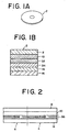
- Fig. 1A illustrates an optical disk 2 in a first embodiment of the present invention
- Fig. 1B shows an exemplary medium structure.
- a SiN dielectric layer 10 having a film thickness of 80 nm is formed on a polycarbonate substrate 8, and a volatile magnetic layer (first magnetic layer) 32 composed of DyFeCo and having a film thickness of 50 nm is formed on the layer 10.
- a nonvolatile magnetic layer (second magnetic layer) 34 composed of TbCo and having a film thickness of 50 nm is formed on the volatile magnetic layer 32.
- a SiN dielectric layer 14 having a film thickness of 80 nm is formed on the nonvolatile magnetic layer 34.
- the above layers 10, 32, 34 and 14 are shaped into films by the technique of sputtering.
- the volatile magnetic layer 32 has a coercive force of 6 kOe or so at a room temperature and contains a rare-earth rich composition whose Curie temperature and compensation temperature are about 250°C and 70°C respectively.
- the nonvolatile magnetic layer 34 has a coercive force of 2 - 3 kOe or so at a room temperature and contains a rare-earth rich composition whose Curie temperature and compensation temperature are about 300°C and 200°C respectively.
- a reflecting film 16 of aluminum is further formed on the dielectric layer 14.
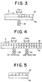
- Fig. 2 illustrates an exemplary use of the medium in the first embodiment.
- the magneto-optical disk 2 in this embodiment has a recording layer 36 composed of a volatile magnetic layer 32 and a nonvolatile magnetic layer 34, so that a user is enabled to selectively use a RAM part 4 which is recordable, reproducible and erasable, or a ROM part 6 which is reproducible only. It is a matter of course that the entire medium can be handled like an ordinary magneto-optical disk used normally as a RAM part.
- a laser beam of a power Pw1 is irradiated to heat the volatile magnetic layer 32 up to the proximity of its Curie temperature, and the volatile magnetic layer 32 is initialized while an external magnetic field is applied thereto from a magnet 38.
- the maximum temperature of the medium never reaches the Curie temperature of the nonvolatile magnetic layer 34, so that there is no possibility of initializing this magnetic layer 34.
- An arrow A indicates the direction of rotation of the disk.
- a laser beam of a power Pw2 which is higher than the foregoing power Pw1 is irradiated during the first rotation of the disk to thereby heat the medium up to the proximity of the Curie temperature of the nonvolatile magnetic layer 34, and this layer 34 is initialized with application of an external magnetic field from the magnet 38.
- an external magnetic field which is inverse to the one at the time of initialization, is applied from a magnet 40 to thereby record the information.
- the rotation velocity of the disk is set to 9 m/sec
- the above condition is satisfied by setting the powers Pw1 and Pw2 to 7 mW and 12 mW or so respectively.
- the essential point resides in that an operation of recording the information in the ROM part may be performed in such a manner that adequate temperature conditions can be achieved by the use of a medium so designed as to conform with the above-described physical conditions.
- the information recorded in the nonvolatile magnetic layer 34 by the operation of Fig. 4 can be neither rewritten nor erased in a magneto-optical disk apparatus operated normally by a user. More specifically, in a magneto-optical disk apparatus operated normally by a user, the disk temperature cannot be raised beyond the Curie temperature of the volatile magnetic layer 32. Therefore, when new information is to be recorded in the volatile magnetic layer 32, the former information is still left unerased in the nonvolatile magnetic layer 34, and consequently the volatile magnetic layer 32 is returned to the former recording state by the exchange bonding force or switched connection in the cooling process of the medium. Accordingly, the disk serves sub stantially as a ROM for the user and there exists no possibility of danger that the acquired information is lost due to accidental or erroneous erasure of the recorded information.
- the operation shown in fig. 4 is performed merely with regard to the area required for recording the information, so that any other area inclusive of the nonvolatile magnetic layer 34 is not initialized as shown in Fig. 5 and is retained in an as-deposition state immediately after manufacture of the medium. Consequently it is always possible to erase the information in the volatile magnetic layer 32 or to record new information therein, and the user is enabled to use this magnetic layer as a RAM area. If a specific ID is prerecorded in a portion of the ROM area by a software provider and an operation needed for erasing such ID is previously programmed in the software, then the ID cannot be read by any illegally copied software, so that it is rendered impossible for the user to start the software, hence ensuring effective protection of the copyright of the software.
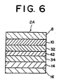
- Fig. 6 shows an exemplary medium structure of a magneto-optical disk 2A in a second embodiment of the present invention.
- a nonmagnetic intermediate layer 42 composed of SiN for example is inserted between a volatile magnetic layer 32 and a nonvolatile magnetic layer 34.
- the volatile magnetic layer 32 and the nonvolatile magnetic layer 34 are magnetostatically coupled to each other.
- This second embodiment functions approximately similarly to the aforementioned first embodiment.
- a magneto-optical recording medium 46 has a plurality of lands 48 and grooves 50 formed alternately, and record marks 64 are formed in both of such lands 48 and grooves 50.
- a plurality of lands 48 and grooves 50 are formed alternately on a transparent substrate 52.
- a dielectric layer 54 is formed on the transparent substrate 52, and a magnetic reproducing layer 56 composed of GdFeCo or the like is formed on the dielectric layer 54.
- the reproducing layer 56 consists of a perpendicular magnetization film.
- a volatile magnetic recording layer 58 composed of TbFeCo or the like is formed on the reproducing layer 56.
- This volatile magnetic recording layer 58 consists of a perpendicular magnetization film.
- a nonvolatile magnetic re cording layer 60 composed of TbCo or the like is formed on the volatile magnetic recording layer 58.
- This nonvolatile magnetic recording layer 60 consists of a perpendicular magnetization film.
- the Curie temperature of the volatile magnetic recording layer 58 is approximately 250°C, and that of the nonvolatile magnetic recording layer is approximately 350°C.
- a dielectric protective layer 62 is formed on the nonvolatile magnetic recording layer 60 to thereby complete a magneto-optical recording medium 46.
- the nonvolatile magnetic recording layer 60 has an ID area 60a at the top of each sector where data is to be recorded. And an ID signal is recorded magneto-optically in the ID area 60a.
- the ID signal in the ID area 60a is recorded by irradiating a high-power laser beam which exceeds the Curie temperature of the nonvolatile magnetic recording layer 60.
- the ID signal may be recorded by the use of an ordinary recording power under the condition that the peripheral velocity of the recording medium is lowered.
- Each sector has a data area 60b in succession to the ID area 60a.
- the data area 60b in the nonvolatile magnetic recording layer 60 is retained in an as-deposition state without being initialized at all. since a land-groove recording technique is adopted in this embodiment, the ID area is provided in both of the lands 48 and the grooves 50.
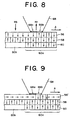
- the recording medium is moved in the direction indicated by an arrow A, and merely the reproducing layer 56 alone is initialized first by an initializing magnetic field Hb. subsequently a reproducing laser beam 68 is irradiated to the recording medium while a reproducing magnetic field Hr is applied thereto in the reverse direction with respect to the initializing magnetic field Hb, so that there are formed, within the beam spot, a low temperature region 66a maintained in the direction of the initializing magnetic field applied to the reproducing layer 56, and also a high temperature region 66b whose direction of magnetization in the reproducing layer 56 is inverted by the reproducing magnetic field Hr.
- the low temperature region 66a serves as a mask since the magnetization in the reproducing layer 56 is directionally uniform in conformity with the initializing magnetic field Hb. Meanwhile in the high temperature region 66b, the direction of magnetization of the ID signal recorded in the nonvolatile magnetic recording layer 60 is transferred to the reproducing layer 56 via the volatile magnetic recording layer 58, so that the ID signal can be read out through the high temperature region 66b in the beam spot.
- the ID signal in the nonvolatile magnetic recording layer 60 is not destroyed, and during the process of fall of the temperature, the ID signal is transferred to the volatile magnetic recording layer 58 by exchange bonding force, whereby the ID signal is protected from destruction.
- the ID signal recorded in the nonvolatile magnetic recording layer 60 can be read out only from the high temperature region 66b in the beam spot according to the principle of magnetically induced superresolution, and consequently there exists no possibility that a problem of crosstalk arises between adjacent tracks.
- a reproducing layer 56' is different from the aforementioned reproducing layer 56 in the foregoing fourth embodiment of Fig. 8 in the point that the layer 56' indicates in-plane magnetization at a room temperature but transits from in-plane magnetization to perpendicular magnetization when heated beyond a predetermined temperature by a reproducing laser beam.
- Any other structure of this embodiment is substantially the same as that of the fourth embodiment shown in Fig. 8.
- a reproducing laser beam 68 When a reproducing laser beam 68 is irradiated to the recording medium, a low temperature region 66a indicating in-plane magnetization and a high temperature region 66b indicating perpendicular magnetization are formed in the reproducing layer 56' within a beam spot.
- An ID signal recorded in an ID area 60a of a nonvolatile magnetic recording layer 60 cannot be read out therefrom since the reproducing layer 56' serves as an in-plane mask in the low temperature region 66a within the beam spot.
- the easy direction of magnetization in the reproducing layer 56' is turned to be perpendicular from the in-plane direction, so that the ID signal recorded in the nonvolatile magnetic recording layer 60 is transferred to the reproducing layer 56' via the volatile magnetic recording layer 58, whereby the ID signal can be read out therefrom through the high temperature region 66b within the beam spot.
- the ID signal is not destroyed even with irradiation of a re cording or erasing laser power as described, and a lower temperature mask is formed within the beam spot so that the ID signal can be reproduced with magnetically induced superresolution, hence preventing any crosstalk of the ID signal between mutually adjacent tracks.
- a SiN dielectric layer 74 is formed on a transparent substrate 72.
- a reproducing layer 76 composed of Gd 30 Fe 55 Co 15 is formed on the dielectric layer 74.
- the reproducing layer 76 is turned from in-plane magnetization to perpendicular one when heated beyond a first predetermined temperature.
- a reproducing auxiliary layer 78 composed of Gd 24 Fe 53 Co 23 is formed on the reproducing layer 76.
- the reproducing auxiliary layer 78 is turned from perpendicular magnetization to in-plane one when heated beyond a second predetermined temperature.
- a switch layer 80 composed of Tb 20 Fe 78 Co 2 is formed on the reproducing auxiliary layer 78. Further a volatile magnetic recording layer 82 composed of Tb 19 Fe 67 Co 14 is formed on the switch layer 80. And a nonvolatile magnetic recording layer 84 composed of Tb 23 Co 77 is formed on the volatile magnetic recording layer 82.
- the Curie temperatures of the above-described reproducing layer 76, reproducing auxiliary layer 78, switch layer 80, volatile magnetic recording layer 82 and nonvolatile magnetic recording layer 84 are 330°C, 280°C, 145°C, 260°C and 350°C, respectively.
- Such layers are 40 nm, 25 nm, 10 nm, 40 nm and 50 nm in film thickness repsectively.
- a SiN protective layer 86 is formed on the nonvolatile magnetic recording layer 84 to complete a magneto-optical recording medium 70.
- Fig. 11 graphically shows the temperature range, where the GdFeCo film is turned to perpendicular magnetization, with respect to the amount of Gd.
- a solid line 39 represents the Curie temperature of GdFeCo.
- Solid lines 41 and 43 represent the case of a single layer film composed of GdFeCo, while broken lines 45 and 47 represent the case of a dual layer film which consists of a GdFeCo film and a recording film of perpendicular magnetization superposed thereon.
- the solid line 41 indicates the temperature at which the single layer film of GdFeCo is turned from perpendicular magnetization to in-plane one
- the solid line 43 indicates the temperature at which the single layer film of GdFeCo is turned from in-line magnetization to perpendicular one
- the broken line 45 indicates the temperature at which the dual layer film consisting of a GdFeCo film and a perpendicular magnetization film is turned from perpendicular magnetization to in-plane one
- the broken line 47 indicates the temperature at which such dual layer film is turned from in-plane magnetization to perpendicular one.
- a symbol A signifies a temperature range of in-plane magnetization.
- a symbol B signifies a temperature range of perpendicular magnetization in the case of a dual layer film including a perpendicular magnetization film, or a temperature range of in-plane magnetization in the case of a single layer film.
- another symbol C signifies a temperature range of perpendicular magnetization.
- an ID signal is recorded in the ID area 84a of the nonvolatile magnetic recording layer 84 by heating the nonvolatile magnetic recording layer 84 beyond its Curie temperature while irradiating a high-power laser beam thereto.
- the data area 84b of the nonvolatile magnetic recording layer 84 adjacent to the ID area 84a is retained in an as-deposition state without being initialized at all.
- a temperature distribution which includes a low temperature region 66a, an intermediate temperature region 66b and a high temperature region 66c within a beam spot.
- the high temperature region 66c is heated beyond the Curie temperature of the switch layer 80.
- the reproducing auxiliary layer 78 has perpendicular magnetization in the low temperature region 66a and the intermediate temperature region 66b, but is turned to in-plane magnetization in the high temperature region 66c. Meanwhile the reproducing layer 76 has, in the low temperature region 66a, in-plane magnetization corresponding to the temperature range A shown in Fig. 11.
- the reproducing auxiliary layer 78 Since the reproducing auxiliary layer 78 has perpendicular magnetization in the intermediate temperature region 66b, the reproducing layer 76 also has perpendicular magnetization in this region. This magnetization corresponds to the case of the aforementioned dual layer film with a perpendicular magnetization film in the temperature range B of Fig. 11. Meanwhile the high temperature region 66c has in-plane magnetization as the reproducing auxiliary layer 78 has in-plane magnetization. This corresponds to the case of the aforementioned single layer film in the temperature rang B of Fig. 11.
- the high temperature region 66c is so preset that the switch layer 80 is heated above the Curie temperature thereof, magnetization of the reproducing auxiliary layer 78 is shielded from the perpendicular magnetization of the volatile magnetic recording layer 82, whereby stable in-plane magnetization is attained.
- the reproducing layer 76 has in-plane magnetization which makes no contribution to the Kerr rotation of the reproducing laser beam, so that a mask can be formed.
- the direction of magnetization of the ID signal recorded in the ID area 84a of the nonvolatile magnetic recording layer 84 can be read out through the intermediate temperature region 66b by watching the reflected light from the magnetization of the reproducing layer 76. More specifically, since the switch layer 80 is below the Curie point thereof, the magnetization of the nonvolatile magnetic recording layer 84 is transferred by exchange bonding successively to the volatile magnetic recording layer 82, the switch layer 80, the reproducing auxiliary layer 78 and the reproducing layer 76, whereby a magneto-optical signal can be obtained from the intermediate temperature region 66b.
- two in-plane magnetization masks can be formed within the spot of the reproducing laser beam, so that the ID signal recorded in the nonvolatile magnetic recording layer 84 is reproducible at high resolution without the necessity of any reproducing magnetic field. Consequently there arises no problem of crosstalk between mutually adjacent tracks.
- Fig. 13 illustrates reproduction of a data area in the sixth embodiment of the present invention.
- a data area 84b of a nonvolatile magnetic recording layer 84 is in an as-deposition state immediately after manufacture of a medium.
- a low temperature mask region 66a and a high temperature mask region 66c are formed within a beam spot, and data recorded in a volatile magnetic recording layer 82 is transferred by exchange bonding to a reproducing layer 76, so that the data can be read out through an intermediate temperature region 66b.
- an ID signal is recorded in the nonvolatile magnetic recording layer.
- the present invention can provide an improved magneto-optical recording medium which is capable of realizing a partial ROM with remarkable facility without the necessity of any particular processing on its substrate.
- Any dealer who wants to sell software to users may acquire mass-produced magneto-optical recording media of the present invention and can record desired software in the ROM areas thereof by employment of a low-cost exclusive apparatus producible with slight modification of a commercially available ordinary apparatus, and on the user side, there is no danger of losing the purchased software even by erroneous manipulation.
Claims (7)
- Support d'enregistrement magnéto-optique comprenant :caractérisé :une première couche (32) d'enregistrement magnétique ayant une première température Tc1 de point de Curie ; etune seconde couche (34) d'enregistrement magnétique formée sur ladite première couche d'enregistrement magnétique et ayant une seconde température Tc2 de point de Curie, dans lequel lesdites températures de point de Curie satisfont Tc1 < Tc2 et lesdites couches d'enregistrement magnétiques peuvent être couplées magnétiquement ;Tc1 étant égale ou inférieure à une température pouvant être atteinte dans un appareil d'enregistrement et/ou de reproduction d'un utilisateur et Tc2 étant plus élevée que la température pouvant être atteinte dans l'appareil d'enregistrement et/ou de reproduction de l'utilisateur ;en ce que ladite seconde couche (34, 60) d'enregistrement magnétique comprend une première zone (84b) qui n'est pas initialisée et qui est maintenue dans un état tel que déposée immédiatement après fabrication du support et permettant l'enregistrement et l'effacement d'information sur ladite première couche d'enregistrement magnétique sur ladite première zone en utilisant ledit appareil d'enregistrement et/ou de reproduction de l'utilisateur, et une seconde zone (84a) qui est initialisée et permettant l'enregistrement et l'effacement seulement par l'utilisation d'un appareil d'enregistrement capable d'atteindre la température Tc2 de point de Curie ; eten ce que lesdites première et seconde couches magnétiques sont couplées magnétiquement de sorte que de l'information enregistrée dans la seconde couche magnétique (34) est transférée de manière forcée à la première couche magnétique (32) tandis que de l'information enregistrée dans la première couche magnétique n'est pas transférée à la seconde couche magnétique.
- Procédé d'utilisation d'un support d'enregistrement magnéto-optique selon la revendication 1, comprenant les étapes consistant :à enregistrer du logiciel dans ladite seconde zone dudit support d'enregistrement à l'aide d'un appareil d'enregistrement capable d'atteindre ladite température Tc2 de point de Curie, ledit appareil d'enregistrement étant utilisé exclusivement par un fabricant de supports et/ou par un fournisseur de logiciels ;à initialiser seulement ladite première couche d'enregistrement magnétique sur ladite première zone ; età utiliser ladite première couche (32) d'enregistrement magnétique sur ladite première zone comme une RAM (mémoire vive) pouvant enregistrer, reproduire et effacer de l'information, dans ledit appareil d'enregistrement et/ou de reproduction de l'utilisateur.
- Support d'enregistrement magnéto-optique selon la revendication 1, comprenant en outre une couche (56, 76) de reproduction magnétique ;
dans lequel lesdites première et seconde couches (32, 34, 58) d'enregistrement magnétique sont formées sur ladite couche de reproduction magnétique et dans lequel ladite seconde couche d'enregistrement magnétique comporte un signal d'identification (ID) enregistré de façon magnéto-optique en haut de chaque secteur d'enregistrement de données. - Support d'enregistrement magnéto-optique selon la revendication 3, dans lequel une zone de données de chaque secteur dans ladite seconde couche (34) d'enregistrement magnétique n'est pas initialisée.
- Support d'enregistrement magnéto-optique selon la revendication 3, dans lequel ladite couche (56, 76) de reproduction magnétique est un film à aimantation perpendiculaire.
- Support d'enregistrement magnéto-optique selon la revendication 3, dans lequel ladite couche (56, 76) de reproduction magnétique est un film à aimantation dans le plan à température ambiante mais devient un film à aimantation perpendiculaire lorsqu'elle est chauffée au-delà d'une température prédéterminée à l'aide d'un faisceau laser de reproduction.
- Support d'enregistrement magnéto-optique selon la revendication 1, comprenant en outre :dans lequel les températures respectives Tc1, Tc2, Tc3 et Tc4 de point de Curie de ladite couche de reproduction, de ladite couche auxiliaire de reproduction, de ladite couche de commutation et de ladite première couche d'enregistrement magnétique satisfont la condition Tc1 > Tc2 > Tc4 > Tc3.une couche (56, 76) de reproduction magnétique ayant une direction d'aimantation privilégiée dans le plan à température ambiante, mais ayant, lorsqu'elle est chauffée au-delà d'une première température prédéterminée, une direction d'aimantation privilégiée perpendiculaire au plan de film ;une couche auxiliaire (78) de reproduction magnétique formée sur ladite couche de reproduction et ayant une direction d'aimantation privilégiée perpendiculaire au plan de film à température ambiante mais ayant une direction d'aimantation privilégiée dans le plan lorsqu'elle est chauffée au-delà d'une seconde température prédéterminée ; etune couche (80) de commutation magnétique formée sur ladite couche auxiliaire de reproduction et ayant une direction d'aimantation privilégiée perpendiculaire au plan de film ;lesdites première et seconde couches d'enregistrement magnétiques étant formées sur ladite couche de commutation magnétique, et ladite seconde couche d'enregistrement magnétique comportant un signal d'identification enregistré de façon magnéto-optique en haut de chaque secteur d'enregistrement de données ; et
Priority Applications (1)
| Application Number | Priority Date | Filing Date | Title |
|---|---|---|---|
| EP00101806A EP1001416B1 (fr) | 1994-03-15 | 1995-02-03 | Méthode d'enregistrement d'information sur un support magnéto-optique |
Applications Claiming Priority (6)
| Application Number | Priority Date | Filing Date | Title |
|---|---|---|---|
| JP4438794 | 1994-03-15 | ||
| JP44387/94 | 1994-03-15 | ||
| JP4438794 | 1994-03-15 | ||
| JP6223278A JP2771462B2 (ja) | 1994-03-15 | 1994-09-19 | 光磁気記録媒体及び該媒体の使用方法 |
| JP223278/94 | 1994-09-19 | ||
| JP22327894 | 1994-09-19 |
Related Child Applications (1)
| Application Number | Title | Priority Date | Filing Date |
|---|---|---|---|
| EP00101806A Division EP1001416B1 (fr) | 1994-03-15 | 1995-02-03 | Méthode d'enregistrement d'information sur un support magnéto-optique |
Publications (2)
| Publication Number | Publication Date |
|---|---|
| EP0673025A1 EP0673025A1 (fr) | 1995-09-20 |
| EP0673025B1 true EP0673025B1 (fr) | 2002-05-15 |
Family
ID=26384272
Family Applications (2)
| Application Number | Title | Priority Date | Filing Date |
|---|---|---|---|
| EP00101806A Expired - Lifetime EP1001416B1 (fr) | 1994-03-15 | 1995-02-03 | Méthode d'enregistrement d'information sur un support magnéto-optique |
| EP95101483A Expired - Lifetime EP0673025B1 (fr) | 1994-03-15 | 1995-02-03 | Milieu d'enregistrement magnéto-optique et procédé pour utiliser celui-ci |
Family Applications Before (1)
| Application Number | Title | Priority Date | Filing Date |
|---|---|---|---|
| EP00101806A Expired - Lifetime EP1001416B1 (fr) | 1994-03-15 | 1995-02-03 | Méthode d'enregistrement d'information sur un support magnéto-optique |
Country Status (4)
| Country | Link |
|---|---|
| US (2) | US5871855A (fr) |
| EP (2) | EP1001416B1 (fr) |
| JP (1) | JP2771462B2 (fr) |
| DE (2) | DE69532898T2 (fr) |
Families Citing this family (13)
| Publication number | Priority date | Publication date | Assignee | Title |
|---|---|---|---|---|
| US9215979B2 (en) * | 1992-11-17 | 2015-12-22 | Robert Bosch Healthcare Systems, Inc. | Multi-user remote health monitoring system |
| US6600713B1 (en) * | 1996-06-26 | 2003-07-29 | Sun Microsystems, Inc. | Recording media having separate read only and read/write areas |
| JP3332750B2 (ja) * | 1996-09-19 | 2002-10-07 | キヤノン株式会社 | 磁気記録媒体、記録方法、再生方法、及び、磁性記録媒体の製造方法 |
| EP1271490B1 (fr) | 1996-10-23 | 2011-12-21 | Panasonic Corporation | Disque optique |
| KR19980063655A (ko) * | 1996-12-02 | 1998-10-07 | 이데이노부유키 | 자기기록매체, 자기기록재생장치 및 몰딩디스크용 메탈몰드의제조방법 |
| DE69739787D1 (de) * | 1996-12-19 | 2010-04-08 | Panasonic Corp | Verfahren zur Aufnahme von einmalig beschreibbaren Informationen auf eine optische Platte. |
| JP2989575B2 (ja) * | 1997-12-12 | 1999-12-13 | 三洋電機株式会社 | 光磁気記録媒体 |
| WO1999049458A1 (fr) * | 1998-03-23 | 1999-09-30 | Warner Music Group, Inc. | Disque optique a format double |
| US6430116B1 (en) * | 1999-05-11 | 2002-08-06 | Mitsubishi Chemical Corporation | Magneto-optical storage medium having first and second recording layers |
| TW476957B (en) * | 1999-09-08 | 2002-02-21 | Mitsubishi Chem Corp | Rewritable compact disk and manufacturing method thereof |
| WO2002009107A1 (fr) * | 2000-07-21 | 2002-01-31 | Fujitsu Limited | Dispositif de disque optique, procede de formatage de disque optique et disque optique ainsi obtenu |
| JP2004326857A (ja) | 2003-04-22 | 2004-11-18 | Sony Corp | 光磁気ディスクおよびその記録再生方法 |
| JP4533854B2 (ja) * | 2006-03-06 | 2010-09-01 | 株式会社東芝 | 磁気記録再生装置、磁気記録方法、及び磁気記録再生方法 |
Citations (5)
| Publication number | Priority date | Publication date | Assignee | Title |
|---|---|---|---|---|
| US3956769A (en) * | 1974-08-12 | 1976-05-11 | Control Data Corporation | Recording system having coinciding servo and data tracks |
| JPS63179436A (ja) * | 1987-01-20 | 1988-07-23 | Sanyo Electric Co Ltd | 光磁気記録媒体 |
| JPS63181143A (ja) * | 1987-01-22 | 1988-07-26 | Sharp Corp | 光磁気記録媒体 |
| JPH05290420A (ja) * | 1992-04-06 | 1993-11-05 | Hitachi Ltd | 光磁気ディスクとその記録再生方法及び装置 |
| EP0575934A2 (fr) * | 1992-06-23 | 1993-12-29 | Deutsche Thomson-Brandt GmbH | Enregistrement et reproduction de l'information en milieux d'emmagasinage ROM-RAM |
Family Cites Families (8)
| Publication number | Priority date | Publication date | Assignee | Title |
|---|---|---|---|---|
| US4467383A (en) * | 1980-02-23 | 1984-08-21 | Sharp Kabushiki Kaisha | Magnetooptic memory medium |
| JPH0231356A (ja) * | 1988-07-20 | 1990-02-01 | Mitsubishi Electric Corp | 情報記録再生装置 |
| JPH0335446A (ja) * | 1989-07-03 | 1991-02-15 | Fujitsu Ltd | 固定化可能部を有する書き換え可能型光ディスク |
| DE69028092T2 (de) * | 1989-11-10 | 1997-04-03 | Mitsubishi Chem Corp | Magnetooptisches aufzeichnungsmedium |
| US5235569A (en) * | 1990-06-13 | 1993-08-10 | Nikon Corporation | Magnetooptical recording method, and apparatus used in the method |
| JP2884433B2 (ja) * | 1990-07-11 | 1999-04-19 | 三菱レイヨン株式会社 | 4―ヒドロキシブチルアクリレート又はメタクリレートの製造法 |
| US5241040A (en) * | 1990-07-11 | 1993-08-31 | International Business Machines Corporation | Microwave processing |
| US5132954A (en) * | 1990-09-24 | 1992-07-21 | International Business Machines Corporation | Controls for optical disk relating to accessing and utilization of such disk |
-
1994
- 1994-09-19 JP JP6223278A patent/JP2771462B2/ja not_active Expired - Fee Related
-
1995
- 1995-01-31 US US08/381,474 patent/US5871855A/en not_active Expired - Fee Related
- 1995-02-03 EP EP00101806A patent/EP1001416B1/fr not_active Expired - Lifetime
- 1995-02-03 DE DE69532898T patent/DE69532898T2/de not_active Expired - Fee Related
- 1995-02-03 DE DE69526691T patent/DE69526691T2/de not_active Expired - Fee Related
- 1995-02-03 EP EP95101483A patent/EP0673025B1/fr not_active Expired - Lifetime
-
1998
- 1998-10-02 US US09/165,902 patent/US6103407A/en not_active Expired - Fee Related
Patent Citations (5)
| Publication number | Priority date | Publication date | Assignee | Title |
|---|---|---|---|---|
| US3956769A (en) * | 1974-08-12 | 1976-05-11 | Control Data Corporation | Recording system having coinciding servo and data tracks |
| JPS63179436A (ja) * | 1987-01-20 | 1988-07-23 | Sanyo Electric Co Ltd | 光磁気記録媒体 |
| JPS63181143A (ja) * | 1987-01-22 | 1988-07-26 | Sharp Corp | 光磁気記録媒体 |
| JPH05290420A (ja) * | 1992-04-06 | 1993-11-05 | Hitachi Ltd | 光磁気ディスクとその記録再生方法及び装置 |
| EP0575934A2 (fr) * | 1992-06-23 | 1993-12-29 | Deutsche Thomson-Brandt GmbH | Enregistrement et reproduction de l'information en milieux d'emmagasinage ROM-RAM |
Also Published As
| Publication number | Publication date |
|---|---|
| DE69526691D1 (de) | 2002-06-20 |
| EP1001416A1 (fr) | 2000-05-17 |
| EP1001416B1 (fr) | 2004-04-14 |
| US6103407A (en) | 2000-08-15 |
| JPH07307041A (ja) | 1995-11-21 |
| JP2771462B2 (ja) | 1998-07-02 |
| EP0673025A1 (fr) | 1995-09-20 |
| DE69532898D1 (de) | 2004-05-19 |
| DE69532898T2 (de) | 2004-08-26 |
| DE69526691T2 (de) | 2002-08-29 |
| US5871855A (en) | 1999-02-16 |
Similar Documents
| Publication | Publication Date | Title |
|---|---|---|
| US5661703A (en) | Optical recording medium having a non-volatile identification code and method for encoding data using same | |
| EP0415449A2 (fr) | Méthode de reproduction pour enregistrement magnéto-optique | |
| JP3375694B2 (ja) | 光磁気ディスク及び光磁気ディスク再生装置 | |
| JP3114204B2 (ja) | 光記録媒体の記録再生方法 | |
| US6103407A (en) | Magneto-optical recording medium and method of using same | |
| EP0549138B1 (fr) | Disque magnéto-optique et méthode de réproduction pour ceci | |
| JPH05101471A (ja) | 光磁気記録再生方法 | |
| CN100498946C (zh) | 磁光盘及使用磁光盘的记录和/或再现方法与装置 | |
| JP3738523B2 (ja) | 記録可能な光ディスク | |
| JP3106514B2 (ja) | 光磁気記録再生方法 | |
| JP3277245B2 (ja) | 光磁気記録媒体及びその再生方法 | |
| JP3554083B2 (ja) | 光磁気記録媒体及び該媒体の情報記録方法 | |
| CA2081153C (fr) | Memoire magneto-optique dans laquelle les superpositions d'ecritures peuvent etre effectuees par modulation du faisceau lumineux et methode d'enregistrement et d'effacement connexe | |
| JP3572686B2 (ja) | 情報記録媒体及びその再生方法 | |
| US6767656B2 (en) | Magneto-optical recording medium and method of reproducing the same | |
| JP2766198B2 (ja) | 光磁気記録媒体 | |
| EP0178423A2 (fr) | Milieu d'enregistrement magnéto-optique | |
| JP2883101B2 (ja) | 情報記録装置 | |
| JPH0388156A (ja) | 光磁気記録再生方法 | |
| JPH0739061Y2 (ja) | 光磁気ディスク | |
| JP3454955B2 (ja) | 光磁気記録媒体及び光磁気記録媒体再生装置 | |
| JPH05298768A (ja) | 光磁気記録再生方法 | |
| JPH103706A (ja) | 光磁気ディスク及びその記録再生装置 | |
| JPH06349127A (ja) | 光磁気ディスク及び記録再生装置 | |
| JPH08167185A (ja) | 光磁気記録媒体及び光磁気記録方法 |
Legal Events
| Date | Code | Title | Description |
|---|---|---|---|
| PUAI | Public reference made under article 153(3) epc to a published international application that has entered the european phase |
Free format text: ORIGINAL CODE: 0009012 |
|
| AK | Designated contracting states |
Kind code of ref document: A1 Designated state(s): DE FR GB |
|
| 17P | Request for examination filed |
Effective date: 19960307 |
|
| 17Q | First examination report despatched |
Effective date: 19981125 |
|
| GRAG | Despatch of communication of intention to grant |
Free format text: ORIGINAL CODE: EPIDOS AGRA |
|
| GRAG | Despatch of communication of intention to grant |
Free format text: ORIGINAL CODE: EPIDOS AGRA |
|
| GRAH | Despatch of communication of intention to grant a patent |
Free format text: ORIGINAL CODE: EPIDOS IGRA |
|
| GRAH | Despatch of communication of intention to grant a patent |
Free format text: ORIGINAL CODE: EPIDOS IGRA |
|
| GRAA | (expected) grant |
Free format text: ORIGINAL CODE: 0009210 |
|
| AK | Designated contracting states |
Kind code of ref document: B1 Designated state(s): DE FR GB |
|
| REG | Reference to a national code |
Ref country code: GB Ref legal event code: FG4D |
|
| REF | Corresponds to: |
Ref document number: 69526691 Country of ref document: DE Date of ref document: 20020620 |
|
| ET | Fr: translation filed | ||
| PLBE | No opposition filed within time limit |
Free format text: ORIGINAL CODE: 0009261 |
|
| STAA | Information on the status of an ep patent application or granted ep patent |
Free format text: STATUS: NO OPPOSITION FILED WITHIN TIME LIMIT |
|
| 26N | No opposition filed |
Effective date: 20030218 |
|
| PGFP | Annual fee paid to national office [announced via postgrant information from national office to epo] |
Ref country code: DE Payment date: 20090129 Year of fee payment: 15 |
|
| PGFP | Annual fee paid to national office [announced via postgrant information from national office to epo] |
Ref country code: GB Payment date: 20090128 Year of fee payment: 15 |
|
| PGFP | Annual fee paid to national office [announced via postgrant information from national office to epo] |
Ref country code: FR Payment date: 20090213 Year of fee payment: 15 |
|
| GBPC | Gb: european patent ceased through non-payment of renewal fee |
Effective date: 20100203 |
|
| REG | Reference to a national code |
Ref country code: FR Ref legal event code: ST Effective date: 20101029 |
|
| PG25 | Lapsed in a contracting state [announced via postgrant information from national office to epo] |
Ref country code: FR Free format text: LAPSE BECAUSE OF NON-PAYMENT OF DUE FEES Effective date: 20100301 |
|
| PG25 | Lapsed in a contracting state [announced via postgrant information from national office to epo] |
Ref country code: DE Free format text: LAPSE BECAUSE OF NON-PAYMENT OF DUE FEES Effective date: 20100901 |
|
| PG25 | Lapsed in a contracting state [announced via postgrant information from national office to epo] |
Ref country code: GB Free format text: LAPSE BECAUSE OF NON-PAYMENT OF DUE FEES Effective date: 20100203 |