EP0673704A1 - Automatische Schweissanlage - Google Patents
Automatische Schweissanlage Download PDFInfo
- Publication number
- EP0673704A1 EP0673704A1 EP95400642A EP95400642A EP0673704A1 EP 0673704 A1 EP0673704 A1 EP 0673704A1 EP 95400642 A EP95400642 A EP 95400642A EP 95400642 A EP95400642 A EP 95400642A EP 0673704 A1 EP0673704 A1 EP 0673704A1
- Authority
- EP
- European Patent Office
- Prior art keywords
- torches
- automatic welding
- installation according
- wire
- welding installation
- Prior art date
- Legal status (The legal status is an assumption and is not a legal conclusion. Google has not performed a legal analysis and makes no representation as to the accuracy of the status listed.)
- Granted
Links
- 238000003466 welding Methods 0.000 title claims abstract description 55
- 238000009434 installation Methods 0.000 title claims abstract description 35
- 239000000463 material Substances 0.000 claims description 7
- 239000000945 filler Substances 0.000 claims description 6
- 239000012530 fluid Substances 0.000 claims description 6
- 230000002441 reversible effect Effects 0.000 claims description 5
- 238000006073 displacement reaction Methods 0.000 claims description 2
- 230000000717 retained effect Effects 0.000 claims description 2
- 239000000725 suspension Substances 0.000 claims description 2
- 210000000941 bile Anatomy 0.000 claims 1
- 238000009792 diffusion process Methods 0.000 claims 1
- 235000010599 Verbascum thapsus Nutrition 0.000 description 77
- 238000000034 method Methods 0.000 description 9
- 239000007789 gas Substances 0.000 description 7
- 230000008569 process Effects 0.000 description 6
- 230000005611 electricity Effects 0.000 description 4
- 244000178289 Verbascum thapsus Species 0.000 description 3
- 230000008901 benefit Effects 0.000 description 3
- 238000013461 design Methods 0.000 description 3
- 238000013459 approach Methods 0.000 description 2
- 230000009467 reduction Effects 0.000 description 2
- 229910001369 Brass Inorganic materials 0.000 description 1
- 239000011324 bead Substances 0.000 description 1
- 210000003323 beak Anatomy 0.000 description 1
- 238000007664 blowing Methods 0.000 description 1
- 239000010951 brass Substances 0.000 description 1
- 230000008859 change Effects 0.000 description 1
- 238000012937 correction Methods 0.000 description 1
- 230000008878 coupling Effects 0.000 description 1
- 238000010168 coupling process Methods 0.000 description 1
- 238000005859 coupling reaction Methods 0.000 description 1
- 239000006185 dispersion Substances 0.000 description 1
- 230000000694 effects Effects 0.000 description 1
- 238000010891 electric arc Methods 0.000 description 1
- 238000000605 extraction Methods 0.000 description 1
- 230000002349 favourable effect Effects 0.000 description 1
- 230000006870 function Effects 0.000 description 1
- 230000015654 memory Effects 0.000 description 1
- 239000000203 mixture Substances 0.000 description 1
- 238000012986 modification Methods 0.000 description 1
- 230000004048 modification Effects 0.000 description 1
- 238000005507 spraying Methods 0.000 description 1
- 239000010935 stainless steel Substances 0.000 description 1
- 229910001220 stainless steel Inorganic materials 0.000 description 1
- 238000013519 translation Methods 0.000 description 1
- XLYOFNOQVPJJNP-UHFFFAOYSA-N water Substances O XLYOFNOQVPJJNP-UHFFFAOYSA-N 0.000 description 1
- 238000004804 winding Methods 0.000 description 1
Images





Classifications
-
- B—PERFORMING OPERATIONS; TRANSPORTING
- B23—MACHINE TOOLS; METAL-WORKING NOT OTHERWISE PROVIDED FOR
- B23K—SOLDERING OR UNSOLDERING; WELDING; CLADDING OR PLATING BY SOLDERING OR WELDING; CUTTING BY APPLYING HEAT LOCALLY, e.g. FLAME CUTTING; WORKING BY LASER BEAM
- B23K9/00—Arc welding or cutting
- B23K9/24—Features related to electrodes
- B23K9/28—Supporting devices for electrodes
- B23K9/287—Supporting devices for electrode holders
-
- B—PERFORMING OPERATIONS; TRANSPORTING
- B23—MACHINE TOOLS; METAL-WORKING NOT OTHERWISE PROVIDED FOR
- B23K—SOLDERING OR UNSOLDERING; WELDING; CLADDING OR PLATING BY SOLDERING OR WELDING; CUTTING BY APPLYING HEAT LOCALLY, e.g. FLAME CUTTING; WORKING BY LASER BEAM
- B23K9/00—Arc welding or cutting
- B23K9/12—Automatic feeding or moving of electrodes or work for spot or seam welding or cutting
- B23K9/133—Means for feeding electrodes, e.g. drums, rolls, motors
- B23K9/1336—Driving means
-
- Y—GENERAL TAGGING OF NEW TECHNOLOGICAL DEVELOPMENTS; GENERAL TAGGING OF CROSS-SECTIONAL TECHNOLOGIES SPANNING OVER SEVERAL SECTIONS OF THE IPC; TECHNICAL SUBJECTS COVERED BY FORMER USPC CROSS-REFERENCE ART COLLECTIONS [XRACs] AND DIGESTS
- Y10—TECHNICAL SUBJECTS COVERED BY FORMER USPC
- Y10T—TECHNICAL SUBJECTS COVERED BY FORMER US CLASSIFICATION
- Y10T483/00—Tool changing
- Y10T483/17—Tool changing including machine tool or component
Definitions
- the invention relates to an automatic welding installation.
- the invention finds its full meaning in situations where the variety of parts to be welded means that the torch has to be changed periodically, but it can also be used if there is a need to replace the welding torch with another tool.
- the current way of acting consists in screwing the torches successively to the arm and unscrewing them manually, which is quite long and occupies a member of staff. It is also necessary to screw or unscrew the end of a flexible sheath carried by the robot arm and which is used to guide the wire of filler material, a reserve of which is wound on the arm and supplied automatically as required, to a wire guide duct, more briefly called wire guide, fixed to the torch and which stops near the gas blowing nozzles or the arc-forming electrode.
- the invention therefore consists in modifying the arm and the torches in order to allow them to be assembled automatically and in a reversible manner, and without any faults in the execution of this operation being to be feared. We refrain from using bolted connections for the arm and torches, and we replace them by other means.
- Known machines and installations do not offer a solution to this problem of constantly adjusting the distance of the electrode while guiding the wire to an invariable position of the electrode from a wire guide separate from the electrode and of the nozzle which carries it.
- the invention precisely solves this difficulty, although it can also be applied to other methods where the end of the torch or the tool must follow a slightly different trajectory from that of the robot arm.
- the invention relates to an automatic welding installation
- a robot arm provided with a control device and with an assembly face of any number of welding torches and provided with a face d 'assembly, and a rack with storage locations for torches
- the arm comprises a wire feed material magazine, a wire advancement device, a wire guide duct fixed to the assembly face and a means of automatic and reversible locking of each of the torches on the arm
- the torches include a wire guide duct
- the assembly faces of the arm and of the torches comprise means for fitting to a single assembly position for which, the assembly faces being joined and the locking being accomplished, the conduit for guiding the wire of the torch locked comes as an extension of the arm wire guide duct.
- the originality of the invention resides in that the torches comprise a movable spout and connected to another part of the torches, to which the assembly face belongs, by a mechanical connection of distance regulation, and the guide wire for the torch wire is composed of a part fixed to the spout and a part fixed to the other part of the torches, the two parts of the guide tube sliding one in the other.
- the electrode or more generally the end of the tool is moved independently of the tool, and the wire remains guided by the wire guide over its entire length.
- the distance controller can be controlled using the arc voltage. If the tension is excessive, the torch is moved back from the parts to be welded, and vice versa. This bondage is known in itself.
- the active element of the welding installation is a robot arm 1 directed by a computer 2 which controls its movements and the state of its operation.
- Arm 1 is made up of several sections articulated between them and movable to give it the desired agility.
- the sections 3 and 4 are articulated around an axis 5 and their movements are governed by a jack 6 which is articulated to them by its two ends.
- the distal section 3 carries a coil 7 which constitutes a reserve of wire 8 of filler material.
- the free end of the wire 8 is threaded into a wire guide 9 running along the distal section 3 and which has the composition of a flexible tubular sheath.
- the wire guide 9 is interrupted at the location of a motor 10 which drives a roller 11 or a similar means to pull the wire 8 by rubbing on it.
- the distal section 3 is terminated by a nozzle 12 which stops at a planar assembly face 13 into which the end of the wire guide 9 is introduced.
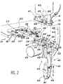
- Torches 20 which will soon be described are put into service after being secured to the assembly face 13. These torches 20 can be of several types, and three different ones have been shown, 20a, 20b and 20c in the figure. 1. They are stored on a rack 21 essentially consisting of a shelf 22 on one side of which open storage compartments 23. A presence sensor 16, visible in FIG. 2, is associated with each storage compartment 23 It is connected to computer 2 and indicates to it if the compartment is empty, in order to receive an abandoned torch 20. The tablet 22 also carries a shear serving as a wire cutter 14. This device is used after a welding process, at least when the torch needs to be changed.
- a ball of melted and then solidified material is in effect formed at the end of the wire 8, and it prevents it from being removed because it would risk being blocked in the torch wire guide which will be described soon.
- the torch is therefore brought onto the wire cutter 14, and the wire 8 is advanced into the slot 15 thereof, where there are a shears and a photoelectric detector which are not shown.
- the detector locates the presence of the wire 8 and commands the shears to close on it, which cuts the end of the wire 8.
- the winding of the wire 8 can then be done to remove it from the torch 20. We see that these operations do not expose to any complications, since it suffices to correctly place the torch 20; or the wire cutter 14 has a known position.
- the tablet 22 is fixed to an upright 25 carrying another tablet 26 on which a control cabinet 27 has been placed, intended for the selective distribution of gas, water and electricity to the torches 20, by means of flexible conduits 28 which connect them to the control cabinet 27.
- the disorderly dispersion of the flexible conduits 28 is avoided by means of a bracket 29 formed at the top of the upright 25 and which dominates over the rest of the installation.
- the bracket 29 is essentially composed of a cantilever beam 30 articulated to the upright 25 about a vertical axis 31 and which carries pulleys 32 to which the flexible conduits 28 are hung by spring cables 33 which relax as soon as the flexible conduits 28 are pulled and lowered by the arm 1, when it carries the torches 20, but which raise the flexible conduits 28 to their starting position as soon as the torches 20 are released.
- the beam 30 is provided with tracks 34 which allow sleds 35, to which the pulleys 32 are suspended, to slide along the beam 30.
- Other spring cables bring the sleds 35 back to the origin of the beam 30, against amount 25, if the elasticity of the flexible conduits 32, which are generally made of rubber, is not sufficient. With such a suspension, it is easy to keep the flexible cables 28 away from the other elements of the installation and in particular to keep them above and to the side of the arm 1. They therefore do not risk being entangled to other elements.
- a spout 40 composed of a frame 41 carrying a nozzle 42 for spraying gas (or housing a electrode 90 according to the welding process envisaged) and a lateral wire guide 43 on the armature 41 and extend next to the nozzle 42; an upper part 44 to be assembled to the arm 1; and a distance regulator 45 which connects the upper part 44 to the spout 40.
- the distance regulator 45 is a device which makes it possible to advance or retract the spout 40 so that it remains at the desired distance from the workpiece which whatever the movements imposed by the programming on the arm 1, which may not be exactly parallel to the weld bead.
- the upper part 44 is formed with an assembly plate 46 terminated by a plane assembly face 47 which is joined to the assembly face 13 of the end piece 12 of the arm 1. It can be seen that the plate d assembly 46 is pierced and flush with the assembly face 47 a central recess 48, interlocking holes 49 lateral, holes for supply conduits 50 in two rows and, towards the ends of the plate assembly 46, an electrical outlet 51 and a thread guide mouth 52, connected to the thread guide 43. Finally, two pairs of pins 53 and 54 point laterally outward near the corners of the assembly plate 46. The pins 53 and 54 are intended for the storage of the torch 20. For this, the shelf 22 carries, to each of the storage compartments 23, a frame 55 which carries four clamps 56.
- Each of the clamps 56 is composed of a lower blade 57 , straight, elastic but fairly rigid, and an upper blade 58 more flexible elastic, the middle part of which is curved in a boss 59 upwards and whose free end 60 is also bent upwards.
- Two of the clips 56 are located at the end of the lateral branches of the frame 55, at the entrance to the storage compartment 23, and the other two are located on a cross member of the frame 55 connecting the branches, at the bottom of the compartment. storage 23. If the torch 20 is introduced into the storage compartment 23 with the necessary accuracy, the pins 53 penetrate into the input clamps 56 and the pins 54 into those at the bottom. They are slid between the blades 57 and 58, push the upper blades 58 by making them bend and are held under the bumps 59. The extraction of the torch 20 by an opposite movement is also accomplished without difficulty.
- the holes in the supply conduits 50 are intended for the possible supply of gas or any kind of fluid to the torch 20 from the arm 1.
- the assembly faces 13 and 47 When the assembly faces 13 and 47 are joined, they come in line with the conduits similar belonging to the arm 1.
- the end face 13 of the arm 1 carries an electrical outlet 61 which is connected to the outlet 51 and makes it possible to supply the torches 20 with electricity; and the wire guide 9 is connected to the wire guide 43.
- the correct placement of the assembly faces 13 and 47 is ensured by a pair of pins 62 of the assembly face 13 of the arm 1, which penetrate into the holes d 'fitting 49.
- the assembly face 13 of the arm 1 is provided with a pneumatic locking cylinder 63 which controls the movement of three lugs 64, arranged at equal distance on a circumference with a radiating arrangement, at the end of a rod 65 which protrudes from the assembly face 13 and enters the central recess 48 when the assembly is carried out.
- the lugs penetrate more precisely into a groove 66 hollowed out in the interior wall of the recess 48 when the active fluid of the jack 63, which extends through the rod 65, causes them to deploy, and they come out of it under a reverse action. .
- the jack 63 is thus controlled by the computer 2 so as to reversibly lock the torch 20, or rather any one of them, to the arm 1.
- the coupling of the sockets 51 and 61 makes it possible to supply an identification signal of the torch 20 entered at the computer 2, which avoids any error, in particular if the torches 20 have been inverted in their compartments of storage 23.
- the control cabinet 27 continuously delivers a particular signal to each of the torches 20, and this signal reaches the electrical outlet 51.
- the computer 2 When the computer 2 has identified the key 20 entered by the arm 1, it acts on the control cabinet 27 to make it deliver to the torch 20 the fluids necessary for its work.
- This identification function is provided by means not shown but simple electronics.
- the wire guide 9 of the arm 1 is terminated by a guide gun 70 which extends through the end piece 12 to the assembly face 13 and is connected to the mouth of thread guide 52 to the assembly of the torch 20.
- a guide gun 70 which extends through the end piece 12 to the assembly face 13 and is connected to the mouth of thread guide 52 to the assembly of the torch 20.
- the mouth of thread guide 52 narrows into a guide cup 71 terminated by a tube 72 which has the ability to slide in a tube 73 of larger diameter, terminated by a funnel 74, the wire guide 43, secured as seen from the spout 40 and the frame 41 of the torch 20, while the tube 72 is integral with the upper part 44 of the torch 20.
- the wire 8 constantly advanced in advance of and during welding, is guided by the guide cup 71 and the funnel 74 and always reaches the end of the wire guide 43, which tapers in front of the nozzle 42 to form a guide nozzle 75.
- the electrode 90 is directed towards a two-way joint mechanical parts 91 and 92 which must be welded.
- the essential elements of the distance regulator 45 are shown: a rack 76 secured to the frame 41, a pinion 77 driven by an electric motor 78, as well as two limit switches 79 at the ends of the rack 76, a sensor median 89 halfway from the previous ones next to the rack 76 and a rotation sensor 80 which measures the movements of the pinion 77.
- the electric motor 78 vertically displaces the rack 76, which meshes with the pinion 77, and therefore adjusts the height torch 20, nozzle 42 and electrode 90 which protrudes from it on the part to be welded.
- the frame 41 slides vertically under the upper part 44 by a mechanical link (not shown) which can take on the appearance of slides or columns.
- the sensors 79, 80 and 89 are connected to the computer 2 by the sockets 51 and 61, which unite sections of electrical lines 83 and 84 belonging to the arm 1 and to the torch 20 and make it possible to perfect this adjustment of the torch 20 instead of being satisfied with a purely autonomous control loop based on the adjustment of the arc voltage on a fixed value, defined in advance, according to which the computer 2 measures the arc voltage between the electrode 90 and the parts 91 and 92 and acts on the electric motor 78 to move the electrode 90.
- the next step is a slow movement of the nozzle 40 in front of the parts in order to control the arc voltage to a known admissible value, in accordance with the previous methods, but it is possible here, as soon as this adjustment is made, to replace the nozzle 40 halfway by moving the robot arm 1 without moving the electrode 90.
- the limit switches 79 detect it and stop the arm robot 1. An alarm is then given to warn the operator.
- the trajectory of the robot arm 1 is, for each of the pairs of parts 91 and 92 of the series, identical to the trajectory programmed, except for a translation correction resulting from the aforementioned replacement of the nozzle 40 halfway just before the start of a welding cycle.
- This position arrangement was specific to the torch 20a of FIG. 1, where the nozzle 42 is vertical and the adjustment of the position of the torch consists of an elongation or retraction movement thereof.
- the adjustment movement would be transverse.
- the guide tube 73 would then be replaced by a guide funnel 81 which would in fact be an extension of the funnel 74.
- the vertical rack 76 would be replaced by a horizontal rack 82, and the rest of the system would not be changed.
- Other systems can also be proposed to ensure correct guiding of the wire 8, according to the possibilities of the torch 20.
- the distance regulator 45 can be the same for all the torches 20 if it can be fixed to the assembly plates 46 by several faces as desired, such as the orthogonal faces 93 and 94 in FIG. 4. These faces are provided with groups of threads 95 of identical arrangements which come as an extension of holes 97 passing through the assembly plate 46. Screws 96 are engaged in the holes 97 and the threads 95 to ensure the desired fixing.
- the motor 10 of FIG. 1 which drives a worm 98 and, indirectly, a first pinion 99 which itself transmits its movement to two parallel toothed wheels 100, the teeth of which extend at the ends and which carry in the center, between the toothed sectors 101, a smooth part 102 hollowed out by a groove 103 in which the wire 8 penetrates and which makes it possible to better entrain it .
- Crazy rollers 104 extend under the wheels 100, in front of the grooves 103, and force the wire 8 to pass through these grooves.
- a die 105 is disposed under the pinion 99: the wire 8 passes through it and is thus straightened between the grooves 103 and the rollers 104, to remove the curvature deformations which it could have acquired on the coil 7 and which would have hindered his progress because of the undulations he would have made in the wire guide 9 and consequent friction on its walls.
- this advance system 110 does not slip and that the wire 8 is actually driven, which can stop if it twists in the wire guide 9 and becomes blocked.
- an encoder 106 of which a graduated wheel is pressed against the wire 8, held straight by an opposite roller 107, near one of the rollers 104. The wire 8 rotates the graduated wheel as it advances, and the computer 2 gives the alarm if the encoder 106 informs it that the wire 8 is stopped.
- Other dies 108 are arranged between the rollers 104, the encoder 106 and the ends of the wire guide 9 to continue to guide the wire 8 properly.
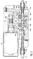
- FIGS. 8 and 9 An improved distance regulator 111 is illustrated in FIGS. 8 and 9. There are certain elements of the preceding regulator 45; they will appear in it with the same reference numbers although they are arranged differently.
- the motor 80 is here connected to a reduction gear 112 by a pair of pulleys 113 and 114 joined by a belt 115.
- An output shaft 116 of the reduction gear 112 carries three stacked circular cams 117a, 117b and 117c.
- Each of the cams 117 has a hollow angular sector 118a, 118b or 118c and is located in front of one of the sensors 79 and 89, in front of which it rotates, so that a feeler button 119 of the sensor concerned is released when it extends in front of the hollow sector 118 of cam 117, but pushed back by cam 117 otherwise.
- the recessed sectors 118 define the references for the stroke of the distance regulator 111.
- the mid-stroke sensor 89 has its button 119 against the edge of the recessed sector 118a of the cam 117a. Rotating the output shaft 116 clockwise would release the button 119, which means that we pass in the other half of the race. This rotation can be continued until the button 119 of one of the limit switches 79 is pushed back by the edge of the hollow sector 118c of the cam 117c.
- This sensor is designated here by 79c. Rotation in opposite directions is also allowed; the key 119 of the other limit switch (designated by 79b) will then eventually arrive at the edge of the hollow sector 118b of the cam 117 and be released, indicating the opposite limit switch.
- the limit switches are marked by opposite movements of the keys 119 of the sensors 79 (release and push), and that the half-stroke sensor 89 always indicates which half of the stroke we are in, which provides information redundant due to different signals which make distance control of the torches safer 20.
- Screws 120 unite the cams 117 with one another and with a pinion 121 of the output shaft 116 which is responsible for driving the rack. The angular and axial sliding of the cams 117 is therefore prohibited.
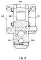
- the torch 20b is illustrated in FIGS. 10 and 11. It is remarkable above all by its adjustment possibilities, which make it possible to use it for varied and sometimes difficult tasks such as welding in hollows.
- Its beak comprises a flange 125 for screwing to the rack 76 and from which rises a rib 126 which receives a pivot 127 and a groove in an arc of a circle 128.
- the main part of the torch 20b is however a barrel 129 finished at the 'rear by a fork 130 articulated to the pivot 127 and whose branches are joined by a bolt 131 which passes through the groove 128. When the bolt is tightened, the fork 130 clamps the rib 126 and ensures the conservation of the orientation of the barrel 129.
- the barrel 129 is as smooth as possible so that there is no risk of hanging it if it has to be pressed into a hollow in the room.
- the thread guide 43 is, for this reason, enclosed in a bore 132 of the barrel 129 over most of its length, except at the end, but this feature makes it easy to adjust its length. It is provided with a rack 133 on a short portion in a widening of the bore 132, and a toothed axis 134 and with a screw head, crossing the barrel 129, meshes with the rack 133 and thus makes it possible to advance or reverse the thread guide 43 with the only help of a screwdriver. A screw 135, also passing through the barrel 129 and a little behind the axis 134, can then be turned to wedge the wire guide 43.
- the wire guide 43 is connected at the rear by a flexible section 136 which can end in the funnel 81 of FIG. 4.
- flexible pipes 137 connect the barrel 129 to the plate d assembly 46 for the transport of fluids and electricity.
- the barrel 129 is hollowed out with holes not shown which extend these flexible pipes up to the electrode 90.
- a hole 138 is provided, which is axial but opens onto the outside, at the front, through a hole in bias 139 directed towards the end of the wire guide 43 and the electrode 90.
- An endoscope 140 can be introduced therein which monitors the correct execution of the welding.
- the torch 20b is equipped with a removable nozzle 142. It is indeed useful not to have to redo the settings of the torch 20b if it is necessary to replace the electrode 90 or the grid 143 for diffusing the gases, which is dirty quickly.
- the nozzle 142 is therefore joined to the barrel 129 by an internal screw 144, which is accessed by removing a short screw 145, coaxial and of larger diameter, which acts as a cover.
- the short screw 145 leaves free a chamber 146 located in front of the internal screw 144 and which occupies the center of the nozzle 142.
- There open gas supply bores 147 extending those of the barrel 129 and which therefore ensure the smooth running of the welding.
- the chamber 146 opens onto the outside by a group of holes 148 arranged around the electrode 90.
Landscapes
- Engineering & Computer Science (AREA)
- Physics & Mathematics (AREA)
- Plasma & Fusion (AREA)
- Mechanical Engineering (AREA)
- Arc Welding In General (AREA)
- Butt Welding And Welding Of Specific Article (AREA)
- Arc Welding Control (AREA)
- Manipulator (AREA)
- Rod-Shaped Construction Members (AREA)
- Lining Or Joining Of Plastics Or The Like (AREA)
- Pressure Welding/Diffusion-Bonding (AREA)
Applications Claiming Priority (2)
| Application Number | Priority Date | Filing Date | Title |
|---|---|---|---|
| FR9403435 | 1994-03-24 | ||
| FR9403435A FR2717724B1 (fr) | 1994-03-24 | 1994-03-24 | Installation de soudage automatique. |
Publications (2)
| Publication Number | Publication Date |
|---|---|
| EP0673704A1 true EP0673704A1 (de) | 1995-09-27 |
| EP0673704B1 EP0673704B1 (de) | 1997-07-30 |
Family
ID=9461362
Family Applications (1)
| Application Number | Title | Priority Date | Filing Date |
|---|---|---|---|
| EP95400642A Expired - Lifetime EP0673704B1 (de) | 1994-03-24 | 1995-03-23 | Automatische Schweissanlage |
Country Status (9)
| Country | Link |
|---|---|
| US (1) | US5512726A (de) |
| EP (1) | EP0673704B1 (de) |
| JP (1) | JP2968927B2 (de) |
| AT (1) | ATE156052T1 (de) |
| CA (1) | CA2145340C (de) |
| DE (1) | DE69500478T2 (de) |
| ES (1) | ES2105846T3 (de) |
| FR (1) | FR2717724B1 (de) |
| GR (1) | GR3024909T3 (de) |
Cited By (2)
| Publication number | Priority date | Publication date | Assignee | Title |
|---|---|---|---|---|
| US7523069B1 (en) | 1999-11-05 | 2009-04-21 | Fronium International Gmbh | Assessing and/or determining of user authorizations using a transponder, a finger print recognition routine or the like |
| WO2010135752A3 (de) * | 2009-05-29 | 2011-04-14 | Fronius International Gmbh | Brennerwechselmodul, schweissbrenner, rohrbogen, brennerhalterung, schlauchpaket für einen schweissbrenner, aufnahmemodul, brennerwechselsystem und verfahren zum automatischen wechseln eines rohrbogens oder einer brennerhalterung eines schweissbrenners |
Families Citing this family (41)
| Publication number | Priority date | Publication date | Assignee | Title |
|---|---|---|---|---|
| BE1009012A4 (nl) * | 1994-12-29 | 1996-10-01 | Willems Peter | Werkwijze en inrichting voor het automatisch lassen van buisleidingen. |
| US5779609A (en) * | 1996-01-16 | 1998-07-14 | Applied Robotics, Inc. | Integrated stud welding robotic tool changing system |
| US6259968B1 (en) * | 1998-07-07 | 2001-07-10 | Daimlerchrysler Corporation | Method and apparatus for establishing work position of manufacturing tool |
| US6089440A (en) * | 1998-07-07 | 2000-07-18 | Chrysler Corporation | Adjustable vehicle assembly tool |
| US6085961A (en) * | 1998-07-07 | 2000-07-11 | Chrysler Corporation | Method and apparatus for establishing user-selected operator load positions for manufacturing tool |
| JP4578614B2 (ja) * | 2000-04-17 | 2010-11-10 | コマツエンジニアリング株式会社 | 溶接装置 |
| US6491612B1 (en) | 2000-10-23 | 2002-12-10 | Ati Industrial Automation, Inc. | Stud welding tool changer |
| WO2003095135A1 (fr) * | 2002-05-13 | 2003-11-20 | Honda Giken Kogyo Kabushiki Kaisha | Equipement et procede de soudage tig |
| US6707004B2 (en) * | 2002-08-06 | 2004-03-16 | Illinois Tool Works Inc. | Apparatus for securing a power cable from a power source to a wire feeder |
| US6720529B2 (en) * | 2002-09-05 | 2004-04-13 | Illinois Tool Works Inc. | Autothread control for a wire feeder of a welding system |
| FR2852540B1 (fr) * | 2003-03-17 | 2005-04-29 | Air Liquide | Ensemble buse/guide-fil pour torche de soudage tig robotise |
| US7329827B2 (en) * | 2004-03-11 | 2008-02-12 | L'air Liquide, Societe Anonyme A Directoire Et Conseil De Surveillance Pour L'etude Et L'exploitation Des Procedes Georges Claude | Wire-guide nozzle assembly for a robotic TIG welding torch |
| JP4700267B2 (ja) * | 2003-08-21 | 2011-06-15 | コマツエンジニアリング株式会社 | 自動溶接方法 |
| US7186944B2 (en) * | 2003-09-18 | 2007-03-06 | Illinois Tool Works Inc. | Method and apparatus for autodetection of plasma torch consumables |
| US6855914B1 (en) * | 2003-09-30 | 2005-02-15 | Illinois Tool Works Inc. | Method and apparatus to automatically determine type of gun connected to a wire feeder |
| JP4286684B2 (ja) * | 2004-02-27 | 2009-07-01 | 株式会社ダイヘン | アーク溶接ロボットにおけるケーブル配設構造 |
| JP3987845B2 (ja) * | 2004-08-13 | 2007-10-10 | ファナック株式会社 | 産業用ロボットの線条体処理構造 |
| JP4233503B2 (ja) * | 2004-09-06 | 2009-03-04 | ファナック株式会社 | アーク溶接ロボットのトーチケーブル処理構造 |
| FR2886186B1 (fr) * | 2005-05-27 | 2009-01-02 | Snecma Moteurs Sa | Installation robotisee de soudage a l'arc |
| FR2887481B1 (fr) * | 2005-06-22 | 2008-12-26 | Air Liquide | Soudo-brasage tig avec transfert de metal par pont liquide |
| US8431862B2 (en) * | 2005-08-25 | 2013-04-30 | Lincoln Global, Inc. | Torch for electric arc welding system |
| US10144080B2 (en) | 2005-08-25 | 2018-12-04 | Lincoln Global, Inc. | Torch for electric arc welding or plasma cutting system |
| FR2904576B1 (fr) * | 2006-08-03 | 2008-09-26 | L'air Liquide | Soudo-brasage tig avec transfert de metal par gouttes et a frequence controlee |
| US8362394B2 (en) * | 2007-08-10 | 2013-01-29 | Illinois Tool Works Inc. | Neck for a robotic welding torch |
| US8803033B2 (en) | 2008-10-22 | 2014-08-12 | Lincoln Global, Inc. | Semi-automatic brazing device |
| US8926484B1 (en) * | 2010-03-29 | 2015-01-06 | Stratasys, Inc. | Head tool changer for use with deposition-based digital manufacturing systems |
| GB201212629D0 (en) | 2012-07-16 | 2012-08-29 | Prec Engineering Technologies Ltd | A machine tool |
| CN103659129B (zh) * | 2012-09-18 | 2016-08-24 | 株式会社大亨 | 转动换位器 |
| JP5698783B2 (ja) * | 2013-03-29 | 2015-04-08 | ファナック株式会社 | 分線盤を備えたロボット |
| US20170129180A1 (en) | 2014-06-09 | 2017-05-11 | Hybrid Manufacturing Technologies Limited | Material processing methods and related apparatus |
| US10046421B2 (en) | 2014-06-11 | 2018-08-14 | Andersen Industries, Inc. | Welding apparatus |
| US9796039B2 (en) * | 2014-07-17 | 2017-10-24 | Changer & Dresser Inc. | Method and apparatus for changing the electrode tip of a TIG welder |
| JP6494323B2 (ja) * | 2015-02-26 | 2019-04-03 | 三菱重工業株式会社 | 加工システム及び工具装着方法 |
| DE102015015179A1 (de) | 2015-11-26 | 2017-06-01 | Hermann von Rautenkranz lnternationale Tiefbohr GmbH & Co., KG - lTAG | Vorrichtung zum Zuführen von Schweißdrähten einer Schweißanlage |
| US9821399B1 (en) * | 2016-07-08 | 2017-11-21 | Norsk Titanium As | Wire arc accuracy adjustment system |
| GB2560737A (en) * | 2017-03-22 | 2018-09-26 | Hybrid Manufacturing Tech Limited | A machine tool |
| DE102018004120A1 (de) * | 2018-05-23 | 2019-11-28 | Psa Automobiles Sa | Vorrichtung und Verfahren zur automatisierten Bearbeitung eines Werkstücks, insbesondere aus einem Guss- oder Werkzeugstahl, Anordnung mit einem Roboterarm und mit der Vorrichtung und deren Verwendung und Verfahren zur Bearbeitung des Werkstücks |
| CN113560721A (zh) * | 2021-08-02 | 2021-10-29 | 工业互联网创新中心(上海)有限公司 | 一种热处理仿真工具校正焊接装置及其加工工艺方法 |
| KR102725417B1 (ko) * | 2021-11-04 | 2024-11-04 | 김오갑 | 용접 장치 |
| US20240066620A1 (en) * | 2022-08-24 | 2024-02-29 | Esab Ab | Feeder mount for robotic welding system |
| CN118848180B (zh) * | 2024-09-27 | 2024-11-26 | 沈阳光大环保科技股份有限公司 | 一种用于细长组焊轴加工的焊接设备 |
Citations (5)
| Publication number | Priority date | Publication date | Assignee | Title |
|---|---|---|---|---|
| DE3400111C1 (de) * | 1984-01-04 | 1985-08-29 | Fraunhofer-Gesellschaft zur Förderung der angewandten Forschung e.V., 8000 München | Vorrichtung zum automatischen Auswechseln von Schweissbrennern in einem Industrieroboterschweisssystem |
| FR2587930A1 (fr) * | 1985-05-30 | 1987-04-03 | Steelweld France | Dispositif de reception et de stockage d'outils dans des lignes de montage |
| US4883939A (en) * | 1988-06-21 | 1989-11-28 | Automatic Tool Control And Management Systems, Inc. | Automatic tool changer for workpiece processing machines |
| US4917619A (en) * | 1987-12-26 | 1990-04-17 | Obara Corporation | Tool changer for welding robot |
| EP0515069A2 (de) * | 1991-05-22 | 1992-11-25 | Kabushiki Kaisha Kokuho | Tragarm für Maschine |
Family Cites Families (4)
| Publication number | Priority date | Publication date | Assignee | Title |
|---|---|---|---|---|
| US4492847A (en) * | 1981-09-30 | 1985-01-08 | Unimation, Inc. | Manipulator welding apparatus with sensing arrangements for weld slam tracking |
| US4539465A (en) * | 1983-12-30 | 1985-09-03 | Westinghouse Electric Corp. | Wire feed system for robot welder |
| US4604787A (en) * | 1984-08-15 | 1986-08-12 | Transamerica Delaval Inc. | Tool changer for manipulator arm |
| IT1241696B (it) * | 1990-09-28 | 1994-01-31 | Sapri Spa | Apparecchio automatico di saldatura |
-
1994
- 1994-03-24 FR FR9403435A patent/FR2717724B1/fr not_active Expired - Fee Related
-
1995
- 1995-03-23 EP EP95400642A patent/EP0673704B1/de not_active Expired - Lifetime
- 1995-03-23 US US08/409,683 patent/US5512726A/en not_active Expired - Lifetime
- 1995-03-23 AT AT95400642T patent/ATE156052T1/de active
- 1995-03-23 ES ES95400642T patent/ES2105846T3/es not_active Expired - Lifetime
- 1995-03-23 CA CA002145340A patent/CA2145340C/fr not_active Expired - Fee Related
- 1995-03-23 DE DE69500478T patent/DE69500478T2/de not_active Expired - Lifetime
- 1995-03-24 JP JP7066613A patent/JP2968927B2/ja not_active Expired - Fee Related
-
1997
- 1997-10-01 GR GR970402556T patent/GR3024909T3/el unknown
Patent Citations (5)
| Publication number | Priority date | Publication date | Assignee | Title |
|---|---|---|---|---|
| DE3400111C1 (de) * | 1984-01-04 | 1985-08-29 | Fraunhofer-Gesellschaft zur Förderung der angewandten Forschung e.V., 8000 München | Vorrichtung zum automatischen Auswechseln von Schweissbrennern in einem Industrieroboterschweisssystem |
| FR2587930A1 (fr) * | 1985-05-30 | 1987-04-03 | Steelweld France | Dispositif de reception et de stockage d'outils dans des lignes de montage |
| US4917619A (en) * | 1987-12-26 | 1990-04-17 | Obara Corporation | Tool changer for welding robot |
| US4883939A (en) * | 1988-06-21 | 1989-11-28 | Automatic Tool Control And Management Systems, Inc. | Automatic tool changer for workpiece processing machines |
| EP0515069A2 (de) * | 1991-05-22 | 1992-11-25 | Kabushiki Kaisha Kokuho | Tragarm für Maschine |
Cited By (3)
| Publication number | Priority date | Publication date | Assignee | Title |
|---|---|---|---|---|
| US7523069B1 (en) | 1999-11-05 | 2009-04-21 | Fronium International Gmbh | Assessing and/or determining of user authorizations using a transponder, a finger print recognition routine or the like |
| EP1230061B2 (de) † | 1999-11-05 | 2010-11-03 | Fronius International GmbH | Festlegen und/oder feststellen von benutzerberechtigungen mittels eines transponders, einer fingerabdruckerkennung oder dergleichen |
| WO2010135752A3 (de) * | 2009-05-29 | 2011-04-14 | Fronius International Gmbh | Brennerwechselmodul, schweissbrenner, rohrbogen, brennerhalterung, schlauchpaket für einen schweissbrenner, aufnahmemodul, brennerwechselsystem und verfahren zum automatischen wechseln eines rohrbogens oder einer brennerhalterung eines schweissbrenners |
Also Published As
| Publication number | Publication date |
|---|---|
| JP2968927B2 (ja) | 1999-11-02 |
| DE69500478D1 (de) | 1997-09-04 |
| CA2145340A1 (fr) | 1995-09-25 |
| FR2717724B1 (fr) | 1996-04-26 |
| DE69500478T2 (de) | 1998-02-05 |
| JPH0839250A (ja) | 1996-02-13 |
| GR3024909T3 (en) | 1998-01-30 |
| ATE156052T1 (de) | 1997-08-15 |
| US5512726A (en) | 1996-04-30 |
| FR2717724A1 (fr) | 1995-09-29 |
| EP0673704B1 (de) | 1997-07-30 |
| ES2105846T3 (es) | 1997-10-16 |
| CA2145340C (fr) | 2004-09-28 |
Similar Documents
| Publication | Publication Date | Title |
|---|---|---|
| EP0673704B1 (de) | Automatische Schweissanlage | |
| WO1996041697A1 (fr) | Installation pour travailler une zone d'un tube au moyen d'un faisceau laser et application aux tubes d'une canalisation sur une barge de pose en mer ou de recuperation de cette canalisation | |
| CH618141A5 (en) | Method and automatic device for coiling a hose | |
| EP0133411A1 (de) | Verfahren und Maschinen für das automatische Schweissen oder Schneiden der Verbindung eines Hauptrohres und eines sekundären Abzweigrohres | |
| EP0611217A1 (de) | Automatische ''in situ'' Schweissmaschine zum Folgen von gekrümmten Konturen, und mit einer Programmiersteuerung zum Extrapolieren | |
| FR2635479A1 (fr) | Automate pour le soudage a l'arc | |
| EP0216695A1 (de) | Verfahren und Maschine zur Herstellung von Rotationshohlkörpern aus in drei verschiedenen Richtungen verlaufenden Gespinstfasern | |
| FR2472918A1 (fr) | Procede et dispositif d'alimentation continue de bande de papier d'une machine de traitement de tabac | |
| FR2576046A1 (fr) | Procede et dispositif pour la fabrication de faisceaux de fils torsades a l'aide d'une toronneuse a double torsion | |
| FR2676947A1 (fr) | Machine de decoupage de toles et de tubes a commande numerique. | |
| BE1003884A5 (fr) | Procede de tuftage et dispositif pour la mise en oeuvre de ce procede. | |
| EP0348534B1 (de) | Drahtschneidemaschine für Elektroerosionsbearbeitung | |
| CA2429859A1 (fr) | Procede de lacage selectif de fils sur des preformes textiles multidimensionnelles et dispositif pour sa mise en oeuvre | |
| EP1089850B1 (de) | Ladevorrichtung einer werkzeugmaschine mit zuarbeitungs-stangen | |
| EP0233351B1 (de) | Maschine zum Schweissen einer Zierkette mit gekreuzten Ringen des Typs mit zwei Strangstücken | |
| CH643015A5 (fr) | Metier a tricoter. | |
| FR2716684A1 (fr) | Banc à broches. | |
| CA2630910A1 (fr) | Dispositif de soudage automatique du type mig/mag | |
| CA2275946A1 (fr) | Machine a cintrer des tubes de faible diametre | |
| EP1551587A2 (de) | Verfahren und vorrichtung zum abziehen und/oder wechseln von elektroden einer schweisszange oder eines schweissgerätes | |
| EP0230398B1 (de) | Vorrichtung zum Binden eines Drahtbundes auf einer Aufwickeleinrichtung | |
| FR2622129A1 (fr) | Machine de conformation d'un troncon de fil ou de tube par pliages successifs | |
| CH582106A5 (en) | Twisting device for large dia. cables - having drawing and feed devices mounted on support moveable between winding up positions | |
| FR2568808A1 (fr) | Dispositif pour le soudage a l'arc au plafond sous flux | |
| FR3132660A1 (fr) | Machine et procédé d’enroulement filamentaire avec systeme de déplacement particulier |
Legal Events
| Date | Code | Title | Description |
|---|---|---|---|
| PUAI | Public reference made under article 153(3) epc to a published international application that has entered the european phase |
Free format text: ORIGINAL CODE: 0009012 |
|
| 17P | Request for examination filed |
Effective date: 19950410 |
|
| AK | Designated contracting states |
Kind code of ref document: A1 Designated state(s): AT BE CH DE ES FR GB GR IT LI NL SE |
|
| GRAG | Despatch of communication of intention to grant |
Free format text: ORIGINAL CODE: EPIDOS AGRA |
|
| GRAH | Despatch of communication of intention to grant a patent |
Free format text: ORIGINAL CODE: EPIDOS IGRA |
|
| 17Q | First examination report despatched |
Effective date: 19961129 |
|
| GRAH | Despatch of communication of intention to grant a patent |
Free format text: ORIGINAL CODE: EPIDOS IGRA |
|
| GRAA | (expected) grant |
Free format text: ORIGINAL CODE: 0009210 |
|
| AK | Designated contracting states |
Kind code of ref document: B1 Designated state(s): AT BE CH DE ES FR GB GR IT LI NL SE |
|
| REF | Corresponds to: |
Ref document number: 156052 Country of ref document: AT Date of ref document: 19970815 Kind code of ref document: T |
|
| REG | Reference to a national code |
Ref country code: CH Ref legal event code: NV Representative=s name: MICHELI & CIE INGENIEURS-CONSEILS Ref country code: CH Ref legal event code: EP |
|
| REF | Corresponds to: |
Ref document number: 69500478 Country of ref document: DE Date of ref document: 19970904 |
|
| GBT | Gb: translation of ep patent filed (gb section 77(6)(a)/1977) |
Effective date: 19970818 |
|
| REG | Reference to a national code |
Ref country code: ES Ref legal event code: FG2A Ref document number: 2105846 Country of ref document: ES Kind code of ref document: T3 |
|
| NLR4 | Nl: receipt of corrected translation in the netherlands language at the initiative of the proprietor of the patent | ||
| REG | Reference to a national code |
Ref country code: GR Ref legal event code: FG4A Free format text: 3024909 |
|
| PLBE | No opposition filed within time limit |
Free format text: ORIGINAL CODE: 0009261 |
|
| STAA | Information on the status of an ep patent application or granted ep patent |
Free format text: STATUS: NO OPPOSITION FILED WITHIN TIME LIMIT |
|
| 26N | No opposition filed | ||
| REG | Reference to a national code |
Ref country code: GB Ref legal event code: IF02 |
|
| REG | Reference to a national code |
Ref country code: FR Ref legal event code: TP Ref country code: FR Ref legal event code: CD |
|
| NLT1 | Nl: modifications of names registered in virtue of documents presented to the patent office pursuant to art. 16 a, paragraph 1 |
Owner name: SNECMA MOTEURS Owner name: LEXVALL |
|
| REG | Reference to a national code |
Ref country code: CH Ref legal event code: PUE Owner name: LEXVALL Free format text: SOCIETE NATIONALE D'ETUDE ET DE CONSTRUCTION DE MOTEURS D'AVIATION, "S.N.E.C.M.A."#2, BOULEVARD DU GENERAL MARTIAL VALIN#F-75015 PARIS (FR) -TRANSFER TO- LEXVALL#2, BOULEVARD DU GENERAL MARTIAL VALIN#75015 PARIS (FR) Ref country code: CH Ref legal event code: PFA Owner name: SNECMA MOTEURS Free format text: LEXVALL#2, BOULEVARD DU GENERAL MARTIAL VALIN#75015 PARIS (FR) -TRANSFER TO- SNECMA MOTEURS#2, BOULEVARD DU GENERAL MARTIAL VALIN#75015 PARIS (FR) |
|
| REG | Reference to a national code |
Ref country code: FR Ref legal event code: CD |
|
| REG | Reference to a national code |
Ref country code: CH Ref legal event code: PFA Owner name: SNECMA Free format text: SNECMA MOTEURS#2, BOULEVARD DU GENERAL MARTIAL VALIN#75015 PARIS (FR) -TRANSFER TO- SNECMA#2, BOULEVARD DU GENERAL MARTIAL VALIN#75015 PARIS (FR) |
|
| NLT1 | Nl: modifications of names registered in virtue of documents presented to the patent office pursuant to art. 16 a, paragraph 1 |
Owner name: SNECMA |
|
| REG | Reference to a national code |
Ref country code: GB Ref legal event code: 732E Free format text: REGISTERED BETWEEN 20120517 AND 20120523 |
|
| PGFP | Annual fee paid to national office [announced via postgrant information from national office to epo] |
Ref country code: IT Payment date: 20120225 Year of fee payment: 18 |
|
| PGFP | Annual fee paid to national office [announced via postgrant information from national office to epo] |
Ref country code: CH Payment date: 20130226 Year of fee payment: 19 Ref country code: DE Payment date: 20130221 Year of fee payment: 19 Ref country code: SE Payment date: 20130226 Year of fee payment: 19 Ref country code: GB Payment date: 20130228 Year of fee payment: 19 |
|
| PGFP | Annual fee paid to national office [announced via postgrant information from national office to epo] |
Ref country code: BE Payment date: 20130222 Year of fee payment: 19 Ref country code: GR Payment date: 20130222 Year of fee payment: 19 Ref country code: NL Payment date: 20130222 Year of fee payment: 19 |
|
| PGFP | Annual fee paid to national office [announced via postgrant information from national office to epo] |
Ref country code: ES Payment date: 20120309 Year of fee payment: 18 Ref country code: AT Payment date: 20130225 Year of fee payment: 19 |
|
| REG | Reference to a national code |
Ref country code: ES Ref legal event code: FD2A Effective date: 20140606 |
|
| PG25 | Lapsed in a contracting state [announced via postgrant information from national office to epo] |
Ref country code: ES Free format text: LAPSE BECAUSE OF NON-PAYMENT OF DUE FEES Effective date: 20130324 |
|
| PGFP | Annual fee paid to national office [announced via postgrant information from national office to epo] |
Ref country code: FR Payment date: 20140320 Year of fee payment: 20 |
|
| REG | Reference to a national code |
Ref country code: DE Ref legal event code: R119 Ref document number: 69500478 Country of ref document: DE |
|
| REG | Reference to a national code |
Ref country code: NL Ref legal event code: V1 Effective date: 20141001 |
|
| REG | Reference to a national code |
Ref country code: CH Ref legal event code: PL |
|
| REG | Reference to a national code |
Ref country code: SE Ref legal event code: EUG |
|
| REG | Reference to a national code |
Ref country code: AT Ref legal event code: MM01 Ref document number: 156052 Country of ref document: AT Kind code of ref document: T Effective date: 20140323 |
|
| GBPC | Gb: european patent ceased through non-payment of renewal fee |
Effective date: 20140323 |
|
| REG | Reference to a national code |
Ref country code: GR Ref legal event code: ML Ref document number: 970402556 Country of ref document: GR Effective date: 20141002 |
|
| PG25 | Lapsed in a contracting state [announced via postgrant information from national office to epo] |
Ref country code: SE Free format text: LAPSE BECAUSE OF NON-PAYMENT OF DUE FEES Effective date: 20140324 |
|
| REG | Reference to a national code |
Ref country code: DE Ref legal event code: R119 Ref document number: 69500478 Country of ref document: DE Effective date: 20141001 |
|
| PG25 | Lapsed in a contracting state [announced via postgrant information from national office to epo] |
Ref country code: CH Free format text: LAPSE BECAUSE OF NON-PAYMENT OF DUE FEES Effective date: 20140331 Ref country code: GB Free format text: LAPSE BECAUSE OF NON-PAYMENT OF DUE FEES Effective date: 20140323 Ref country code: DE Free format text: LAPSE BECAUSE OF NON-PAYMENT OF DUE FEES Effective date: 20141001 Ref country code: LI Free format text: LAPSE BECAUSE OF NON-PAYMENT OF DUE FEES Effective date: 20140331 Ref country code: GR Free format text: LAPSE BECAUSE OF NON-PAYMENT OF DUE FEES Effective date: 20141002 |
|
| PG25 | Lapsed in a contracting state [announced via postgrant information from national office to epo] |
Ref country code: AT Free format text: LAPSE BECAUSE OF NON-PAYMENT OF DUE FEES Effective date: 20140323 Ref country code: NL Free format text: LAPSE BECAUSE OF NON-PAYMENT OF DUE FEES Effective date: 20141001 |
|
| PG25 | Lapsed in a contracting state [announced via postgrant information from national office to epo] |
Ref country code: IT Free format text: LAPSE BECAUSE OF NON-PAYMENT OF DUE FEES Effective date: 20140323 |
|
| PG25 | Lapsed in a contracting state [announced via postgrant information from national office to epo] |
Ref country code: BE Free format text: LAPSE BECAUSE OF NON-PAYMENT OF DUE FEES Effective date: 20140331 |