EP0674947B1 - Dispositif à transporteur - Google Patents
Dispositif à transporteur Download PDFInfo
- Publication number
- EP0674947B1 EP0674947B1 EP94117061A EP94117061A EP0674947B1 EP 0674947 B1 EP0674947 B1 EP 0674947B1 EP 94117061 A EP94117061 A EP 94117061A EP 94117061 A EP94117061 A EP 94117061A EP 0674947 B1 EP0674947 B1 EP 0674947B1
- Authority
- EP
- European Patent Office
- Prior art keywords
- high voltage
- work
- conveyor device
- coating
- zone
- Prior art date
- Legal status (The legal status is an assumption and is not a legal conclusion. Google has not performed a legal analysis and makes no representation as to the accuracy of the status listed.)
- Expired - Lifetime
Links
Images


Classifications
-
- B—PERFORMING OPERATIONS; TRANSPORTING
- B05—SPRAYING OR ATOMISING IN GENERAL; APPLYING FLUENT MATERIALS TO SURFACES, IN GENERAL
- B05B—SPRAYING APPARATUS; ATOMISING APPARATUS; NOZZLES
- B05B5/00—Electrostatic spraying apparatus; Spraying apparatus with means for charging the spray electrically; Apparatus for spraying liquids or other fluent materials by other electric means
- B05B5/08—Plant for applying liquids or other fluent materials to objects
- B05B5/082—Plant for applying liquids or other fluent materials to objects characterised by means for supporting, holding or conveying the objects
- B05B5/084—Plant for applying liquids or other fluent materials to objects characterised by means for supporting, holding or conveying the objects the objects lying on, or being supported above conveying means, e.g. conveyor belts
-
- B—PERFORMING OPERATIONS; TRANSPORTING
- B05—SPRAYING OR ATOMISING IN GENERAL; APPLYING FLUENT MATERIALS TO SURFACES, IN GENERAL
- B05B—SPRAYING APPARATUS; ATOMISING APPARATUS; NOZZLES
- B05B13/00—Machines or plants for applying liquids or other fluent materials to surfaces of objects or other work by spraying, not covered by groups B05B1/00 - B05B11/00
- B05B13/02—Means for supporting work; Arrangement or mounting of spray heads; Adaptation or arrangement of means for feeding work
- B05B13/0221—Means for supporting work; Arrangement or mounting of spray heads; Adaptation or arrangement of means for feeding work characterised by the means for moving or conveying the objects or other work, e.g. conveyor belts
- B05B13/025—Means for supporting work; Arrangement or mounting of spray heads; Adaptation or arrangement of means for feeding work characterised by the means for moving or conveying the objects or other work, e.g. conveyor belts the objects or work being present in bulk
Definitions
- the present invention concerns a conveyor device used for electrostatic coating by applying a high voltage on a work to be coated instead of applying the high voltage on a coating machine.
- Electrostatic coating of a work such as a car body has been conducted so far by applying a high voltage of from -80 V to 120 kV on an electrostatic coating machine that jets out a paint while grounding a work placed on a conveyor truck to the earth.
- electrostatic coating is generally applied by using an insulative paint. Movements for environmental protection have become popular world wide in recent years and it has been keenly advocated to regulate the use of organic solvents such as hydrocarbons that yield substances causing public pollution and, in compliance therewith, it has been recommended also in the industrial field of coating to cease the use of insulative paints that consume a great amount of deleterious organic solvents such as thinner and transfer to electrostatic coating using aqueous paints causing no public pollution.
- the applicant has already proposed a conveyor device capable of applying a high voltage on a work so that electrostatic coating can be conducted using an electroconductive paint without providing insulation means to the paint supply system (Japanese Utility Model Laid-Open Hei 3-105948 and Hei 4-16796).
- Fig. 10 illustrates such a proposed conveyor device, in which a work W is placed on a truck 71 running on a rail 70, and an electrode attachment 72 for applying a high voltage to the work is attached in an insulated state by means of insulation posts 73 such as made of porcelain for keeping a necessary insulation distance.
- a current collector rail 74 is disposed along a transporting direction of the truck 71 in a high voltage application zone for conducting electrostatic coating under application of a high voltage to the work, and a contact 75 connected to the attachment 72 is in sliding contact with the collector rail 74.
- the contact 75 is brought into sliding contact with the collector rail 74 to apply the high voltage on the work W, so that electrostatic coating can be conducted without providing insulation means to the electrostatic coating machine, the paint supply system, the floor conveyor or the like.
- the insulation oil if it is used in the coating zone, would splash and deposit to the work, which repels the paint and brings about a problem of defective coating.
- EP 0 473 156 A2 discloses an electrostatic coating facility with an insulated conveyor disposed in the coating zone comprising insulation supports each standing at a predetermined distance along the coating zone and a frame supported horizontally between the supports.
- a pair of sprockets is disposed at both ends of the frame and an endless chain is provided so that a conveyor truck carrying the car body thereon is trailed and caused to run along a conveyor rail disposed along the upper end of the frame.
- a high voltage cable from a high voltage generator is connected with the conveyor rail or the frame so that a high voltage is applied by way of the conveyor truck to the car body. Due to the application of high voltage to the work via electrical contact the problems as discussed above cannot be solved.
- a conveyor device for applying a high voltage to a work with an electromagnetic wave transmission means that is disposed in the coating booth for transmitting electromagnetic waves to the running base during running of the running base in the high voltage application zone in which electrostatic coating is carried out by applying a high voltage to the work
- the running base has, provided therewith, a low voltage generation means for receiving electromagnetic waves transmitted from the electromagnetic transmission means in a contactless fashion and outputting a low voltage, and has, provided therewith, a high voltage generation means for stepping up a low voltage outputted from the low voltage generation means to a predetermined voltage and supplying a high voltage to the electrode attachment.
- electromagnetic waves are transmitted from an electromagnetic wave transmission means disposed in a coating booth to the running base, and a low voltage generation means disposed in the running base outputs a low voltage.
- the electromagnetic wave transmission means used comprises an induction rail laid in a high vol tage application zone and constituting a primary circuit for electromagnetic induction
- the low voltage generation means used comprises pick-up coils that constituting a secondary circuit for electromagnetic induction. Then, if the pick-up coils are disposed to the running base so as to oppose in a contactless fashion to the induction rail, a low voltage is supplied only while both of them oppose to each other, namely, only during transportation of the work in the high voltage application zone and the low voltage is inputted to a high voltage generation means mounted on the running base and then stepped up, with no requirement for the ON-OFF control of the voltage.
- the electromagnetic waves are thus supplied in the contactless fashion and, in addition, it can be supplied from such a low energy source as capable of outputting a low voltage, a high voltage is applied by way of an electrode attachment to the work, without generating sparks, also upon transportation of the running base into and out of the high voltage application zone.
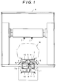
- Fig. 1 is a front elevational view illustrating a coating booth in which a conveyor device according to the present invention is disposed and Fig. 2 is a side elevational view of the coating booth.
- a plurality of slats (running bases) 3 each having an electrode attachment 2 mounted thereon for applying a high voltage on a work W mounted on the running base are disposed each at a predetermined distance to an endless chain 5 that runs between a loading device C and a relay device R disposed before and after a coating booth 4 (Fig. 2).
- a high voltage application zone H is formed in which electrostatic coating is carried out in a state of applying a high voltage on the work W.
- a coating machine T grounded to the earth is disposed so that it can track along a transporting direction of the slat 3, and an induction rail (electromagnetic wave transmission means) 6 constituting a primary circuit for electromagnetic induction is disposed for a predetermined length along the transporting direction of the work W.
- the induction rail 6 is disposed so as to situate, for example, below the slat 3 running in the coating booth 4, and covered with a cover 7 having a longitudinal slit 7a.
- Pick-up coils (low voltage generation means) 8 constituting a secondary circuit for electromagnetic introduction are attached to the slat 3 at a position opposing to the induction rail 6, and the pick-up coils 8 are so adapted to oppose the induction rail 6 in the contactless fashion in a state being inserted through the slit 7a when the slat 3 runs in the high voltage application H.
- an insulation post 9 is disposed vertically to each of the slats 3 for supporting the electrode attachment 2 in the insulated state and a small-sized high voltage generator 10 and a high resistance circuit 11 are disposed on both right and left sides of the insulation post 9.
- the high voltage generator 10 is adapted to step-up an induced electromotive force outputted from the pick-up coils 8 as a primary power source, supply a high voltage to the electrode attachment 2 and apply the high voltage to the work W.
- the high resistance circuit 11 serves to remove static electric charges remaining on the work W and the electrode attachment 2 after the slat 3 has passed the high voltage application zone H and application of the high voltage to the work W has been completed.
- the resistance value of the circuit 11 is selected, for example, as from several thousands to ten thousand MOhm for preventing short-circuit during application of the high voltage.
- a grounding switch may be disposed for connecting the electrode attachment 2 to the earth when a certain alarm signal is inputted.
- an AC current at a low voltage (for example, about 300 to 500 V) is supplied to the induction rail 6 and the movement of the conveyor device main body 1 is started.
- the work W is placed on the slat 3 by a loading device C disposed before the coating booth 4 and then transported into the coating booth 4.
- the pick-up coils 8 attached to the slat 3 are inserted through the slit 8a in the cover 7 and moved while being opposed to the induction rail 6 in a contactless fashion.
- the high voltage generator 10 is adapted to step-up the induced electromotive force as a primary power source and, finally, supply a high DC voltage to the electrode attachment 2, the high voltage is applied by way of the electrode attachment 2 to the work W and electrostatic coating can be carried out by merely atomizing a paint from the coating machine T grounded to the earth.
- the high voltage is applied on the work W only while the work W runs in the high voltage application zone, and the static charges have been removed already upon transfer of the work W to the next conveyor by the relay device R, to ensure operation safety.
- the high resistance circuit 11 is grounded to the earth also during running of the slats 3 in the high voltage application zone H and during application of the high voltage on the work, so that the charges at high voltage applied on the work slightly escape to the earth but the high resistance value of the circuit 11 can prevent flow of overcurrent or short-circuit.
- the primary source for the high voltage generator is supplied in the contactless fashion during running of the slat 3 in the high voltage application zone H, the high voltage applied on the work W can automatically be supplied/stopped with no ON-OFF circuit operation at all.
- Fig. 3 is a side elevational view illustrating another conveyor device according to the present invention and Fig. 4 is a plan view thereof. Portions and components in Fig. 4 identical with those shown in Figs. 1 and 2 carry the same reference numerals, for which detailed descriptions will be omitted.
- a microwave transmission system is adopted instead of supplying the primary power source to the high voltage generator 10 by the electromagnetic induction system as in the previous embodiment.
- a microwave transmission antenna (electromagnetic wave transmission means) 21 is disposed in a coating booth 4 for transmitting microwaves to a slat 3 running in a high voltage application zone H.
- Each slat 3 is provided with a microwave receiving antenna 22 that opposes the microwave transmission antenna 21, and it is so adapted that a voltage outputted from the receiving antenna (low voltage generation means) 22 is supplied to a high voltage generator 10.
- the microwave transmission antenna 21 is adapted, for example, as shown in Fig. 4 such that it transmits microwaves for a predetermined range of irradiation angle which is enough to cover a moving distance of the microwave receiving antenna 22 from the entrance to the exit of the slat 3 for the high voltage application zone H, so that the microwave receiving antenna 22 can receive the microwaves throughout this distance.
- a voltage outputted from the microwave receiving antenna 22 is converted into a DC or AC current at a predetermined voltage, and a high voltage generator 10 steps-up the same as a primary power source, supplies a high DC voltage to the electrode attachment 2 and applies a high voltage to the work W placed on the attachment 2.
- the microwaves outputted from the microwave transmission antenna 21 are received by the microwave receiving antenna 22 disposed on the slat 3 carrying the work W from the entrance till the exit of the slat 3 of the high voltage application zone H.
- the received microwaves are converted into a DC or AC current at a predetermined voltage, and supplied to the high voltage generator 10.
- the high voltage generator 10 is adapted to step-up the thus induced electromotive force as the primary power source and supply a high voltage to the electrode attachment 2, a high voltage is applied by way of the electrode attachment 2 to the work W, and electrostatic coating can be applied by merely atomizing a paint from the coating machine T grounded to the earth.
- the primary power source for the high voltage generator is supplied in a contactless fashion only during running of the slat 3 in the high voltage application zone H, the high voltage applied to the work W can be automatically supplied/stopped with no circuit ON-OFF generation at all.
- Fig. 5 is a front elevational view illustrating a further conveyor device according to the present invention and Fig. 6 is a side elevational view thereof.
- Portions or components in Fig. 5 identical with those in Figs. 1 and 2 carry the same reference numerals, for which detailed explanations will be omitted.
- microwaves are guided to a waveguide tube for supplying a primary power source.
- a waveguide tube (electromagnetic wave transmission means) 31 of a predetermined length is disposed along the transporting direction of a work W.
- the waveguide tube 31 situates, for example, below a slat 3 running in the coating booth 4 and has a magnetron 32 attached at one end for oscillating microwaves.
- the waveguide tube 31 has a cross section of a large width in which a slit 33 is opened with a width less than one-half wavelength in the longitudinal direction along the center line of the bottom, and a phase transducer 34 having 1/4 wavelength depth is disposed to the opening of the slit 33 for preventing leakage of microwaves.
- a microwave receiving antenna 35 is disposed vertically movably to the top end of a bracket 36 on the slat 3 such that the antenna is inserted within the slit 33 of the waveguide tube 31 in a contactless fashion.
- the microwave receiving antenna 35 is so adapted that it is resiliently biased downwardly by a spring 37 and inserted by the 1/4 wavelength into the slit 33 being urged at the lower end of the antenna by a guide rail 38 disposed below the waveguide tube 31.
- microwaves received by the microwave receiving antenna 35 are converted into a DC or AC current at a predetermined voltage, and supplied to and stepped-up by a high voltage generator 10.
- the high voltage generator 10 is adapted to supply a high DC voltage finally to an electrode attachment 2, the high voltage is applied by way of the electrode attachment 2 on the work W and electrostatic coating can be carried out by merely atomizing a paint from a coating machine T grounded to the earth.
- movement of the conveyor device 1 is started in a state in which the magnetron 32 is actuated to supply the microwaves in the waveguide tube 31.
- the width of the slit is selected to less than one-half wavelength, and since the phase transducer 34 is disposed, the microwaves are not leaked from the slit 32.
- the lower end of the microwave receiving antenna 35 is raised by the guide rail 38 against the resiliency of a spring 37 and the top end is inserted into the waveguide tube 31.
- the microwaves transmitting in the waveguide tube 31 are received, converted into a DC or AC current at a predetermined voltage and supplied as a primary power source for the high voltage generator 10.
- a high voltage is supplied from the high voltage generator 10 to the electrode attachment 2, and the high voltage is applied on the work W, and electrostatic coating can be carried out by merely atomizing a paint from the coating device grounded to the earth (not illustrated).
- the microwave receiving antenna 35 is withdrawn from the waveguide tube 31 by the resiliency of the spring 37 and the microwaves can no more be received, so that application of the high voltage on the work W is stopped.
- the primary power source for the high voltage generator is supplied in the contactless fashion only during running of the slat 3 in the high voltage application zone H also in this embodiment, the high voltage applied to the work W can be automatically supplied/stopped with no circuit ON-OFF operation at all.
- the microwaves are transmitted by way of the waveguide tube 31, they do not leak to the outside of the waveguide tube 31 to ensure high safety, as well as the high voltage can be turned ON and OFF at an accurate timing by the insertion and withdrawal of the antenna 35.
- the microwave receiving antenna 35 is inserted and withdrawn by inserting and retracting it into and out of the slit 33 in this embodiment, the invention is not restricted only to such a constitution but the microwave receiving antenna 35 may be fixed and the antenna 35 may be introduced from both end faces of the waveguide tube 31 through slits formed on both end faces of the waveguide tube 31 in contiguous with the slit 33.
- Fig. 7 is a side elevational view illustrating a further conveyor device and each of Fig. 8 and Fig. 9 illustrates a main portion thereof.
- Portions or components in Fig 7 identical with those in Fig. 1 and Fig. 2 carry the same reference numerals, for which detailed explanations will be omitted.
- a preheat zone for heating a work to a predetermined temperature is provided so that excessive water content in coating membranes is eliminated as soon as possible after completion of the coating and before entry to a baking/drying furnace. If a work completed with coating is directly entered and heated rapidly in the baking/drying furnace at a high temperature, (for example, about 140 o C), the excessive water content in the coating membranes is evaporated and bubbles are formed to the surface of the coating membranes to cause defective coating and the provision of the preheat zone can prevent such disadvantage.
- a high temperature for example, about 140 o C
- the conveyor device main body 1 comprises a slat conveyor in which an electrode attachment 2 for carrying works W and applying a high voltage thereon is attached each at a predetermined distance by way of an insulation post 9 to slat, 3 which are caused to run by an endless chain 5.
- the endless chain 5 is adapted to advance above the floor of a coating zone T, run through the coating zone T and a preheat zone P and then retract to a level below the floor before a baking/drying furnace F in adjacent with the preheat zone P.
- the slat 3 has pick-up coils 8 disposed thereon for opposing, in a contactless fashion, to an induction rail 6 disposed in the coating zone T, and has a high voltage generator 10 mounted thereon for stepping-up an electromotive force induced by pick-up coils 8 to a predetermined high voltage, so that a high voltage is applied by the high voltage generator 10 to the electrode attachment 2.
- the pick-up coils 8 and the high voltage generator 10 are disposed at the rear face of the slat 3 for the sake of the cleaning performance of the slat conveyor 2.
- radiation panels (radiation heaters) 40R, 40L, 40U having a plurality of infrared lamps arranged thereon are disposed along three sides, i.e., right and left side walls and ceiling walls such that they oppose to the right and left sides and the upper side of the work W transported by the conveyor device main body 1. Further, heat shield plates 41R, 41L are disposed between the conveyor device main body 1 and the radiation panels 40R, 40L disposed on both right and left sides of the main body 1 for shielding heat radiated from each of the panels 40R, 40L to the conveyor device main body 1.
- each of the heat shield plates 41R, 41L is made of a metal plate formed so as to cover the portion of the conveyor device main body 1 exposed above the floor and, more specifically, the plate is disposed vertically from both of the right and left sides of the slat 3 running above the floor to a height about at the upper end of the electrode attachment 2, and the top ends of the plates are inwardly bent horizontally so as to oppose to both of the right and left ends at the upper end of the electrode attachment 2.
- the heat shield plates 41R, 41L are made, for example, of metal plates having a heat insulator sandwiched between, or cooling pipes 42 are attached therealong for circulately supplying cooling water as required.
- a cleaning zone S for cleaning to remove a paint deposited in the coating zone T and a drying zone T for drying.
- shower nozzles 43 for blowing cleaning liquid (for example, cleaning water) to the insulation post 9 and a rotary brush 44 for brushing the insulation post 9 at the same time with blowing of the cleaning liquid from the shower nozzles 43 to remove deposited paints.
- cleaning liquid for example, cleaning water
- another shower nozzles may be disposed for blowing cleaning liquid to the electrode attachment 2 and, further, a rotary brush (not illustrated may be disposed for brushing both of the right and left sides and the rear side of the electrode attachment 2 as required.
- the drying zone D is provided for drying the wetted insulation post 9 so that a high voltage applied to the electrode attachment 2 does not leak by way of the wetted insulation post 9 when the electrode attachment 2 completed with cleaning enters the coating zone T, in which air blowers 45 are disposed for blowing air to both of the electrode attachment 2 and the insulation posts 9.
- a hot blow may be blown, and an air blow for blowing a cold blow may be disposed subsequent to the air blower for blowing the hot blow in order to cool the electrode attachment 2 and the insulation post 9 heated by the air blow.
- the work W is at first carried on the electrode attachment 2 of the conveyor device main body 1 before the coating zone T and transported into the coating zone T.
- the pick-up coils 8 attached to the slat 3 oppose to the induction rail 6 and generate an induced electromotive force, which is stepped-up by the high voltage generator 7 and a high voltage is applied by way of the electrode attachment 2 to the work W.
- electrostatic coating can be carried out using an aqueous paint without applying a high voltage to a coating machine (not illustrated).
- the aqueous paint sprayed from the coating machines disposed on both right and left sides of the conveyor device main body 1 deposits not only on the work W but also on the electrode attachment 2 that carries the work W and on the insulation post 9 that supports the attachment 2.
- heat is emitted from the IR lamps disposed on the radiation panels 40R, 40L, 40U to the surface of the work W to dry the surface to such an extent as removing an excessive water content contained in coating membranes.
- the paint deposited on the electrode attachment 2 and on the insulation post 9 passes the preheat zone in a not yet dried state as it is.
- the work W upon delivery out of the preheat zone, is transferred by the relay device R to the succeeding conveyor that runs in the baking/drying furnace F.
- the slat 3 unloaded with the work W retracts by the endless chain 5 to a level below the floor and runs below the floor as far as the coating zone T. Since the paint deposited on the insulation post 9 is still wetted, if the work W is transported as it is to the coating zone T and a high voltage is applied to the electrode attachment 2, a high voltage may possibly leak by way of the paint deposited on the insulation post 9 to the slat 3 as a grounded body.
- the paint deposited on the surface of the post 9 is remove by cleaning and dried in the cleaning zone S and the drying zone D formed below the floor.
- cleaning water is sprayed from the shower nozzle 43 to the insulation post 9 and, simultaneously, the insulation post 9 is brushed by the rotary brush 44 to remove the paint deposited on the insulation post 9.
- the paint deposited on the rear side of the electrode attachment 2 can also be cleaned to remove by them.
- the slat 3 after passing through the cleaning zone S, is transported to the drying zone D, blown with a hot blow from air blowers 45 disposed on both right and left sides of the conveyor device main body 1 running below the floor, so that the electrode attachment 2 and the insulation post 9 wetted by the cleaning water are dried.
- the electrode attachment 2 advances above the floor and arrives at the coating zone T, since the electrode attachment 2 and the insulation post 9 for mounting and supporting the attachment to the slat 3 are already dried, if a high voltage is applied to the electrode attachment 2, it does not leak to the slat 3 as a body grounded to the earth.
- the shower nozzle 43 and the rotary brush 44 are used together but the present invention is not restricted only thereto, but only the shower nozzle 43 may be disposed and cleaning water may be sprayed from the shower nozzle 43 at a pressure sufficient to remove the paint deposited on the insulation post 9.
- the drying zone D air is blown from the air blowers 45 to dry the work W, but the present invention is not restricted only thereto but, the work may also be dried by the heat emitted from the radiation heater such as infrared lamps.
- a high voltage generator for supplying a high voltage to an electrode attachment is mounted on each of running bases, and a primary power source for the high voltage generator is supplied to the running base in a contactless fashion only during running of the running base in a high voltage application zone, so that a current collector rail and contacts are no more necessary.
- a high voltage applied to the work can be automatically supplied and stopped at a predetermined timing with no circuit on-off operation or without particular voltage control, so that this can provide an excellent effect capable of applying the high voltage to the work transported in the high voltage application zone with no worry of generating sparks.
- a conveyor device main body is disposed in adjacent with a coating zone and a preheat zone, so that the work completed with coating can be transported as it is to the preheat zone without transferring to other conveyor, and the excessive water content in coating membranes can be dried to remove instantly to prevent deposition of dusts on the surface, as well as prevent dripping of the coating membranes.
- the conveyor deposited with a paint does not run in a baking/drying furnace, the paint is not baked to the conveyor and since heat shield plates are disposed in the preheat zone so as to cover the electrode attachment and the support post, in the preheat zone, drying for the surface of the coating membranes deposited on the electrode attachment and the support post can surely be prevented, without hindering drying for the surface of the coating layers on the work just after the completion of coating, to enhance the conveyor cleaning performance.
- the conveyor device main body is retracted below the floor and cleaned by water washing with a cleaning device before the paint is baked in a state deposited to the insulation post, the paint deposited on the insulation post can be cleaned to remove extremely simply. Further, since the water content deposited on the insulation post and on the electrode attachment supported by the post is then dried, if it is returned by the endless chain into the coating zone again and a high voltage is applied to the electrode attachment, the high voltage does not leak by way of the insulation post to the slat as a body grounded to the earth.
Landscapes
- Electrostatic Spraying Apparatus (AREA)
- Control Of Conveyors (AREA)
- Application Of Or Painting With Fluid Materials (AREA)
- Automobile Manufacture Line, Endless Track Vehicle, Trailer (AREA)
Claims (6)
- Dispositif convoyeur servant à appliquer une haute tension sur une pièce en oeuvre (W) transportée le long d'une piste prédéterminée, pendant le transport dans une zone d'application de haute tension (H) formée dans une cabine d'enduction (4), et dans lequel un corps principal (1) de dispositif convoyeur comprend une base mobile (3) se déplaçant le long d'une piste prédéterminée formée dans la cabine d'enduction (4) et un moyen de fixation d'électrodes (2) relié à ladite base mobile (3) dans un état isolé, pour transporter une pièce en oeuvre (W) et y appliquer une haute tension, le dispositif convoyeur étant caractérisé en ce que des moyens de transmission d'ondes électromagnétiques (6) sont disposés dans ladite cabine d'enduction (4) pour transmettre des ondes électromagnétiques à ladite base mobile (3) pendant le déplacement de ladite base mobile (3) dans la zone d'application de haute tension (H) dans laquelle l'enduction électrostatique est effectuée par application d'une haute tension à ladite pièce en oeuvre (W), et ladite base mobile (3) est munie de moyens de production de basse tension (8) destinés à recevoir les ondes électromagnétiques transmises par lesdits moyens de transmission d'ondes électromagnétiques (6), sans aucun contact avec ces derniers, et émettre une basse tension, et est munie de moyens de production de haute tension (10) pour élever une basse tension émise par lesdits moyens de production de basse tension (8) à une tension prédéterminée et fournir une haute tension audit moyen de fixation d'électrodes (2).
- Dispositif convoyeur selon la revendication 1, caractérisé en ce que les moyens de transmission d'ondes électromagnétiques sont constitués d'un rail d'induction (6) formant un circuit primaire d'induction électromagnétique, qui est disposé dans la cabine d'enduction (4) sur une longueur prédéterminée dans la direction de transport de la pièce en oeuvre à l'intérieur de la zone d'application de haute tension (H), pour effectuer une enduction électrostatique par application d'une haute tension sur ladite pièce en oeuvre (W), les moyens de production de basse tension sont constitués de bobines exploratrices (8) formant un circuit secondaire d'induction électromagnétique, disposé en regard dudit rail d'induction (6), sans aucun contact avec ce dernier, et les moyens de production de haute tension (10) sont munis de la base mobile (3) et élèvent la tension émise par les bobines exploratrices (8) par induction électromagnétique par rapport audit rail d'induction (6).
- Dispositif convoyeur selon la revendication 1, caractérisé en ce que les moyens de transmission d'ondes électromagnétiques sont constitués d'une antenne de transmission hyperfréquence (21) transmettant des ondes hyperfréquence à la base mobile (3), les moyens de production de basse tension sont constitués d'une antenne réceptrice d'ondes hyperfréquence (22) destinée à recevoir les ondes hyperfréquence transmises par ladite antenne de transmission d'ondes hyperfréquence (21), et les moyens de production de haute tension (10) servant à élever la tension émise par ladite antenne réceptrice (22) sont munis de la base mobile (3).
- Dispositif convoyeur selon la revendication 1, caractérisé en ce que les moyens de transmission d'ondes électromagnétiques sont constitués d'un tube guide d'ondes (31) disposé le long de la direction de transport de ladite pièce en oeuvre (W), un oscillateur hyperfréquence (32) est fixé audit tube guide d'ondes (31) pour produire une oscillation hyperfréquence, les moyens de production de basse tension montés sur la base mobile (3) sont constitués d'une antenne réceptrice d'ondes hyperfréquence (35) insérée, sans entrer en contact avec elle, dans une fente (33) formée dans ledit tube guide d'ondes (31), et les moyens de production de haute tension (10) sont montés sur la base mobile (3) pour élever une tension émise depuis ladite antenne (35).
- Dispositif convoyeur selon l'une des revendications 1 à 4, caractérisé en ce que le corps principal (1) du dispositif convoyeur comprend un convoyeur à lattes ayant une base mobile constituée d'une latte (3) conçue pour être déplacée par une chaíne sans fin (5) de telle sorte que la latte (3) avance au-dessus du plancher d'une zone d'enduction (T) et se rétracte au-dessous du plancher en amont d'un four de cuisson/séchage (F), un moyen de fixation d'électrodes (2) qui est monté sur la latte (3) au moyen d'une tige d'isolation (9) pour transporter une pièce en oeuvre (W) et y appliquer une haute tension, un dispositif de nettoyage, servant à laver et à nettoyer à l'eau les deux côtés droit et gauche de chaque tige d'isolation (9), et un dispositif de séchage pour sécher les tiges d'isolation (9) et le moyen de fixation d'électrode (2) supporté par ces dernières et lavé et nettoyé à l'eau par ledit dispositif de nettoyage, étant disposés le long de la direction d'avancement dudit corps principal (1) du dispositif convoyeur, rétracté au-dessous du plancher.
- Dispositif convoyeur selon la revendication 5, caractérisé en ce que ladite chaíne sans fin (5) est disposée de façon à avancer au-dessus du plancher de la zone d'enduction (T), à se déplacer dans ladite zone d'enduction (T) et dans une zone de préchauffage (P), puis à se rétracter au-dessous du plancher, en amont du four de cuisson/séchage (F) contigu à ladite zone de préchauffage (P) , des plaques formant bouclier thermique (41R, 41L) étant disposées dans ladite zone de préchauffage (P), entre ledit corps principal de dispositif convoyeur (1) d'une part et ses deux côtés droit et gauche d'autre part, pour protéger le corps principal (1) du dispositif convoyeur de la chaleur émise par chacun des éléments chauffants disposés dans la zone de préchauffage (P).
Applications Claiming Priority (2)
| Application Number | Priority Date | Filing Date | Title |
|---|---|---|---|
| JP06426194A JP3244932B2 (ja) | 1994-04-01 | 1994-04-01 | コンベア装置 |
| JP64261/94 | 1994-04-01 |
Publications (3)
| Publication Number | Publication Date |
|---|---|
| EP0674947A2 EP0674947A2 (fr) | 1995-10-04 |
| EP0674947A3 EP0674947A3 (fr) | 1995-12-06 |
| EP0674947B1 true EP0674947B1 (fr) | 1999-03-03 |
Family
ID=13253085
Family Applications (1)
| Application Number | Title | Priority Date | Filing Date |
|---|---|---|---|
| EP94117061A Expired - Lifetime EP0674947B1 (fr) | 1994-04-01 | 1994-10-28 | Dispositif à transporteur |
Country Status (6)
| Country | Link |
|---|---|
| US (1) | US5603769A (fr) |
| EP (1) | EP0674947B1 (fr) |
| JP (1) | JP3244932B2 (fr) |
| KR (1) | KR100313752B1 (fr) |
| CA (1) | CA2133599C (fr) |
| DE (1) | DE69416821T2 (fr) |
Cited By (1)
| Publication number | Priority date | Publication date | Assignee | Title |
|---|---|---|---|---|
| EP2613995B1 (fr) | 2010-09-10 | 2016-12-21 | Eisenmann SE | Installation de traitement de surface de carrosseries de véhicules |
Families Citing this family (13)
| Publication number | Priority date | Publication date | Assignee | Title |
|---|---|---|---|---|
| DE19725048A1 (de) * | 1997-06-13 | 1998-12-17 | Audi Ag | Anlage zur Oberflächenbehandlung von Gegenständen |
| JP4182182B2 (ja) * | 1999-05-14 | 2008-11-19 | 株式会社椿本チエイン | ハイブリッド搬送台車 |
| DE10012658A1 (de) * | 2000-01-21 | 2001-07-26 | Wurster Gerd | Pulverbeschichtungsanlage |
| DE10216440B4 (de) * | 2002-04-12 | 2010-11-25 | Krups Gmbh | Förderbahn auf Flurhöhe mit geraden, gebogenen und/oder winkligen Förderbahn-Abschnitten für einen oder mehrere Werkstückträger |
| KR100573769B1 (ko) | 2003-12-10 | 2006-04-25 | 삼성전자주식회사 | 비접촉 급전시스템 |
| ATE527907T1 (de) * | 2004-04-23 | 2011-10-15 | Panasonic Elec Works Co Ltd | Gebläseheizung mit elektrostatischem zerstäuber |
| KR100811179B1 (ko) | 2006-05-02 | 2008-03-07 | 태산도장 주식회사 | 수성 및 수용성도료용 마이크로파 건조장치 |
| US8367978B2 (en) * | 2006-10-05 | 2013-02-05 | Magna International Inc. | Hybrid infrared convection paint baking oven and method of using the same |
| DE102006049670A1 (de) * | 2006-10-18 | 2008-04-24 | W + I Oberflächen-Systeme GmbH | Verfahren und Vorrichtung zum Transport von Gegenständen |
| DE102008046503A1 (de) * | 2008-09-09 | 2010-05-06 | Eisenmann Anlagenbau Gmbh & Co. Kg | Förderkette und Trockenofen mit einer solchen |
| JP2016025685A (ja) * | 2014-07-17 | 2016-02-08 | 株式会社松浦電弘社 | 電力供給システム、給電装置、受電装置、及び電力供給方法 |
| CN108689104B (zh) * | 2018-05-24 | 2023-11-10 | 天津中德应用技术大学 | 一种电气控制自动化生产定频操作设备 |
| CN120081140B (zh) * | 2025-04-27 | 2025-08-26 | 四川旌峰新材料有限公司 | 一种丙烯酸羟基酯成品输送装置及方法 |
Family Cites Families (16)
| Publication number | Priority date | Publication date | Assignee | Title |
|---|---|---|---|---|
| US3875892A (en) * | 1974-01-14 | 1975-04-08 | Ransburg Corp | Apparatus for avoiding sparks in an electrostatic coating system |
| US3937180A (en) * | 1974-04-10 | 1976-02-10 | The Gyromat Corporation | Apparatus for electrostatically charging workpieces for spray coating application |
| JPS55114366A (en) * | 1979-02-28 | 1980-09-03 | Nippon Radiator Co Ltd | Feeding device of coating material for electrostatic coating |
| JPS5833184B2 (ja) * | 1979-09-07 | 1983-07-18 | 新日本製鐵株式会社 | 高炉不定形炉材用バインダ− |
| JPS6475077A (en) * | 1987-09-12 | 1989-03-20 | Taikisha Kk | Spray electrostatic coating method |
| DE3800448A1 (de) * | 1988-01-09 | 1989-07-20 | Ribnitz Peter | Verfahren und vorrichtung zur durchlaufbeschichtung von werkstuecken |
| JPH03105948A (ja) * | 1989-09-19 | 1991-05-02 | Fujitsu Ltd | 半導体記憶装置 |
| JP2619098B2 (ja) * | 1989-12-27 | 1997-06-11 | トリニティ工業株式会社 | 導電性塗料の静電塗装設備とそれに使用する集電レール |
| JPH0416796A (ja) * | 1990-05-10 | 1992-01-21 | Rigaku Corp | 放射線遮蔽カバー用構造部材およびその製造方法 |
| JPH0436483A (ja) * | 1990-06-01 | 1992-02-06 | Matsushita Electric Ind Co Ltd | マイクロ波プラズマ発生装置 |
| JP2528201B2 (ja) * | 1990-06-26 | 1996-08-28 | トリニティ工業株式会社 | 静電塗装用荷電装置 |
| JP2810796B2 (ja) * | 1990-12-28 | 1998-10-15 | トリニティ工業株式会社 | 導電性塗料の静電塗装設備 |
| JP2567506B2 (ja) * | 1990-08-30 | 1996-12-25 | トリニティ工業株式会社 | 導電性塗料の静電塗装設備 |
| US5190588A (en) * | 1990-08-30 | 1993-03-02 | Trinity Industrial Corporation | Electrostatic coating facility for electroconductive coating material |
| EP0509374B1 (fr) * | 1991-04-18 | 1998-03-04 | Alltrista Corporation | Procédé et appareil pour sécher et cuire un revêtement d'un substrat métallique |
| JP3105948U (ja) | 2004-02-09 | 2004-12-09 | 町子 前野 | カッティングシートきちんと |
-
1994
- 1994-04-01 JP JP06426194A patent/JP3244932B2/ja not_active Expired - Fee Related
- 1994-10-04 CA CA002133599A patent/CA2133599C/fr not_active Expired - Fee Related
- 1994-10-27 US US08/329,853 patent/US5603769A/en not_active Expired - Fee Related
- 1994-10-28 EP EP94117061A patent/EP0674947B1/fr not_active Expired - Lifetime
- 1994-10-28 DE DE69416821T patent/DE69416821T2/de not_active Expired - Fee Related
- 1994-11-08 KR KR1019940029166A patent/KR100313752B1/ko not_active Expired - Fee Related
Cited By (1)
| Publication number | Priority date | Publication date | Assignee | Title |
|---|---|---|---|---|
| EP2613995B1 (fr) | 2010-09-10 | 2016-12-21 | Eisenmann SE | Installation de traitement de surface de carrosseries de véhicules |
Also Published As
| Publication number | Publication date |
|---|---|
| EP0674947A2 (fr) | 1995-10-04 |
| DE69416821D1 (de) | 1999-04-08 |
| CA2133599A1 (fr) | 1995-10-02 |
| DE69416821T2 (de) | 1999-11-11 |
| JPH07265748A (ja) | 1995-10-17 |
| CA2133599C (fr) | 2004-02-17 |
| KR100313752B1 (ko) | 2002-04-06 |
| JP3244932B2 (ja) | 2002-01-07 |
| US5603769A (en) | 1997-02-18 |
| KR950029155A (ko) | 1995-11-22 |
| EP0674947A3 (fr) | 1995-12-06 |
Similar Documents
| Publication | Publication Date | Title |
|---|---|---|
| EP0674947B1 (fr) | Dispositif à transporteur | |
| EP1270089B1 (fr) | Appareil et procédé de revêtements en poudre avec une chauffage par induction | |
| US6797066B2 (en) | Apparatus and method for powder coating | |
| KR19990006252A (ko) | 정전분체 도장장치 | |
| SE8604886D0 (sv) | Anordning for och sett att belegga glas | |
| KR101740706B1 (ko) | 핀튜브용 법랑 코팅 장치에 사용되는 무정전 건식 순수 프리트 도포 장치 및 도포 방법 | |
| US5738727A (en) | Device for electrostatic spraying of a coating product | |
| PT908922E (pt) | Camara de processo para o processamento de plasma e dispositivo empregando essa camara de processo | |
| GB2145641A (en) | Apparatus for electrostatically coating articles | |
| EP0426258B1 (fr) | Procédé et dispositif pour fabriquer des corps de boîte en métal pourvus d'un revêtement intérieur | |
| JP2004512569A (ja) | 電子写真式のプリント装置 | |
| KR200180388Y1 (ko) | 강관의 폴리에틸렌 피복 장치 | |
| KR200214734Y1 (ko) | 무늬형성을 위한 분체도장 장치 | |
| KR20010045857A (ko) | 강관의 폴리에틸렌 피복방법 및 피복 장치 | |
| JPH07313909A (ja) | コンベア装置 | |
| JPH08103694A (ja) | コンベア装置 | |
| JPH08103696A (ja) | コンベア装置 | |
| JPH08294661A (ja) | 塗装方法 | |
| JPH07313920A (ja) | 塗装設備 | |
| JP3626296B2 (ja) | 乾燥炉 | |
| JPH08103693A (ja) | コンベア装置 | |
| KR100443581B1 (ko) | 플라즈마 디스플레이 패널의 격벽 형성 방법 및 장치 | |
| JPH08229454A (ja) | ワーク加電塗装システム | |
| KR0133698Y1 (ko) | 음극선관의 펀넬 건조장치 | |
| JPH08229455A (ja) | ワーク加電塗装システム |
Legal Events
| Date | Code | Title | Description |
|---|---|---|---|
| PUAI | Public reference made under article 153(3) epc to a published international application that has entered the european phase |
Free format text: ORIGINAL CODE: 0009012 |
|
| AK | Designated contracting states |
Kind code of ref document: A2 Designated state(s): DE FR GB IT SE |
|
| PUAL | Search report despatched |
Free format text: ORIGINAL CODE: 0009013 |
|
| AK | Designated contracting states |
Kind code of ref document: A3 Designated state(s): DE FR GB IT SE |
|
| 17P | Request for examination filed |
Effective date: 19960307 |
|
| 17Q | First examination report despatched |
Effective date: 19970904 |
|
| GRAG | Despatch of communication of intention to grant |
Free format text: ORIGINAL CODE: EPIDOS AGRA |
|
| GRAG | Despatch of communication of intention to grant |
Free format text: ORIGINAL CODE: EPIDOS AGRA |
|
| GRAH | Despatch of communication of intention to grant a patent |
Free format text: ORIGINAL CODE: EPIDOS IGRA |
|
| GRAH | Despatch of communication of intention to grant a patent |
Free format text: ORIGINAL CODE: EPIDOS IGRA |
|
| GRAA | (expected) grant |
Free format text: ORIGINAL CODE: 0009210 |
|
| AK | Designated contracting states |
Kind code of ref document: B1 Designated state(s): DE FR GB IT SE |
|
| REF | Corresponds to: |
Ref document number: 69416821 Country of ref document: DE Date of ref document: 19990408 |
|
| ITF | It: translation for a ep patent filed | ||
| ET | Fr: translation filed | ||
| PLBE | No opposition filed within time limit |
Free format text: ORIGINAL CODE: 0009261 |
|
| STAA | Information on the status of an ep patent application or granted ep patent |
Free format text: STATUS: NO OPPOSITION FILED WITHIN TIME LIMIT |
|
| 26N | No opposition filed | ||
| PGFP | Annual fee paid to national office [announced via postgrant information from national office to epo] |
Ref country code: SE Payment date: 20011023 Year of fee payment: 8 |
|
| REG | Reference to a national code |
Ref country code: GB Ref legal event code: IF02 |
|
| PGFP | Annual fee paid to national office [announced via postgrant information from national office to epo] |
Ref country code: GB Payment date: 20021018 Year of fee payment: 9 |
|
| PG25 | Lapsed in a contracting state [announced via postgrant information from national office to epo] |
Ref country code: SE Free format text: LAPSE BECAUSE OF NON-PAYMENT OF DUE FEES Effective date: 20021029 |
|
| EUG | Se: european patent has lapsed | ||
| PGFP | Annual fee paid to national office [announced via postgrant information from national office to epo] |
Ref country code: FR Payment date: 20031021 Year of fee payment: 10 |
|
| PG25 | Lapsed in a contracting state [announced via postgrant information from national office to epo] |
Ref country code: GB Free format text: LAPSE BECAUSE OF NON-PAYMENT OF DUE FEES Effective date: 20031028 |
|
| PGFP | Annual fee paid to national office [announced via postgrant information from national office to epo] |
Ref country code: DE Payment date: 20031229 Year of fee payment: 10 |
|
| GBPC | Gb: european patent ceased through non-payment of renewal fee |
Effective date: 20031028 |
|
| PG25 | Lapsed in a contracting state [announced via postgrant information from national office to epo] |
Ref country code: DE Free format text: LAPSE BECAUSE OF NON-PAYMENT OF DUE FEES Effective date: 20050503 |
|
| PG25 | Lapsed in a contracting state [announced via postgrant information from national office to epo] |
Ref country code: FR Free format text: LAPSE BECAUSE OF NON-PAYMENT OF DUE FEES Effective date: 20050630 |
|
| REG | Reference to a national code |
Ref country code: FR Ref legal event code: ST |
|
| PG25 | Lapsed in a contracting state [announced via postgrant information from national office to epo] |
Ref country code: IT Free format text: LAPSE BECAUSE OF NON-PAYMENT OF DUE FEES;WARNING: LAPSES OF ITALIAN PATENTS WITH EFFECTIVE DATE BEFORE 2007 MAY HAVE OCCURRED AT ANY TIME BEFORE 2007. THE CORRECT EFFECTIVE DATE MAY BE DIFFERENT FROM THE ONE RECORDED. Effective date: 20051028 |