EP0674959A1 - Méthode pour soumettre à un pressage isostatique un élément moulé à partir d'un matériau en poudre - Google Patents
Méthode pour soumettre à un pressage isostatique un élément moulé à partir d'un matériau en poudre Download PDFInfo
- Publication number
- EP0674959A1 EP0674959A1 EP95302192A EP95302192A EP0674959A1 EP 0674959 A1 EP0674959 A1 EP 0674959A1 EP 95302192 A EP95302192 A EP 95302192A EP 95302192 A EP95302192 A EP 95302192A EP 0674959 A1 EP0674959 A1 EP 0674959A1
- Authority
- EP
- European Patent Office
- Prior art keywords
- powder
- molded material
- isostatic pressing
- rubber film
- rubber
- Prior art date
- Legal status (The legal status is an assumption and is not a legal conclusion. Google has not performed a legal analysis and makes no representation as to the accuracy of the status listed.)
- Granted
Links
- 239000000463 material Substances 0.000 title claims abstract description 90
- 238000000462 isostatic pressing Methods 0.000 title claims abstract description 22
- 238000000034 method Methods 0.000 title claims abstract description 16
- 229920001971 elastomer Polymers 0.000 claims abstract description 49
- 239000000919 ceramic Substances 0.000 claims description 3
- 239000002184 metal Substances 0.000 claims description 3
- 239000000843 powder Substances 0.000 abstract description 20
- 229920000126 latex Polymers 0.000 description 15
- 230000000052 comparative effect Effects 0.000 description 11
- 230000015572 biosynthetic process Effects 0.000 description 5
- 238000005238 degreasing Methods 0.000 description 5
- 238000005245 sintering Methods 0.000 description 4
- 230000003068 static effect Effects 0.000 description 4
- XLYOFNOQVPJJNP-UHFFFAOYSA-N water Substances O XLYOFNOQVPJJNP-UHFFFAOYSA-N 0.000 description 4
- LYCAIKOWRPUZTN-UHFFFAOYSA-N Ethylene glycol Chemical compound OCCO LYCAIKOWRPUZTN-UHFFFAOYSA-N 0.000 description 3
- 239000011230 binding agent Substances 0.000 description 3
- 230000007547 defect Effects 0.000 description 3
- 239000007789 gas Substances 0.000 description 3
- 238000001746 injection moulding Methods 0.000 description 3
- 239000004816 latex Substances 0.000 description 3
- 238000004519 manufacturing process Methods 0.000 description 3
- 238000000465 moulding Methods 0.000 description 3
- 239000002245 particle Substances 0.000 description 3
- IJGRMHOSHXDMSA-UHFFFAOYSA-N Atomic nitrogen Chemical compound N#N IJGRMHOSHXDMSA-UHFFFAOYSA-N 0.000 description 2
- 239000004372 Polyvinyl alcohol Substances 0.000 description 2
- 229910052581 Si3N4 Inorganic materials 0.000 description 2
- CETPSERCERDGAM-UHFFFAOYSA-N ceric oxide Chemical compound O=[Ce]=O CETPSERCERDGAM-UHFFFAOYSA-N 0.000 description 2
- 229910000422 cerium(IV) oxide Inorganic materials 0.000 description 2
- 150000001875 compounds Chemical class 0.000 description 2
- 238000010304 firing Methods 0.000 description 2
- 239000012530 fluid Substances 0.000 description 2
- 239000000203 mixture Substances 0.000 description 2
- 230000035515 penetration Effects 0.000 description 2
- 229920002451 polyvinyl alcohol Polymers 0.000 description 2
- 238000003825 pressing Methods 0.000 description 2
- HQVNEWCFYHHQES-UHFFFAOYSA-N silicon nitride Chemical compound N12[Si]34N5[Si]62N3[Si]51N64 HQVNEWCFYHHQES-UHFFFAOYSA-N 0.000 description 2
- LEDMRZGFZIAGGB-UHFFFAOYSA-L strontium carbonate Chemical compound [Sr+2].[O-]C([O-])=O LEDMRZGFZIAGGB-UHFFFAOYSA-L 0.000 description 2
- 229910000018 strontium carbonate Inorganic materials 0.000 description 2
- 241000743339 Agrostis Species 0.000 description 1
- 239000012298 atmosphere Substances 0.000 description 1
- 238000005266 casting Methods 0.000 description 1
- 238000009694 cold isostatic pressing Methods 0.000 description 1
- 238000001816 cooling Methods 0.000 description 1
- 229910052878 cordierite Inorganic materials 0.000 description 1
- 238000005520 cutting process Methods 0.000 description 1
- 238000007872 degassing Methods 0.000 description 1
- JSKIRARMQDRGJZ-UHFFFAOYSA-N dimagnesium dioxido-bis[(1-oxido-3-oxo-2,4,6,8,9-pentaoxa-1,3-disila-5,7-dialuminabicyclo[3.3.1]nonan-7-yl)oxy]silane Chemical compound [Mg++].[Mg++].[O-][Si]([O-])(O[Al]1O[Al]2O[Si](=O)O[Si]([O-])(O1)O2)O[Al]1O[Al]2O[Si](=O)O[Si]([O-])(O1)O2 JSKIRARMQDRGJZ-UHFFFAOYSA-N 0.000 description 1
- 238000002845 discoloration Methods 0.000 description 1
- 238000001125 extrusion Methods 0.000 description 1
- 238000010438 heat treatment Methods 0.000 description 1
- 238000003754 machining Methods 0.000 description 1
- 238000002844 melting Methods 0.000 description 1
- 230000008018 melting Effects 0.000 description 1
- 239000011259 mixed solution Substances 0.000 description 1
- 229910052757 nitrogen Inorganic materials 0.000 description 1
- 239000012299 nitrogen atmosphere Substances 0.000 description 1
- 239000012188 paraffin wax Substances 0.000 description 1
- 238000007789 sealing Methods 0.000 description 1
- 239000000243 solution Substances 0.000 description 1
- 229910001220 stainless steel Inorganic materials 0.000 description 1
- 239000010935 stainless steel Substances 0.000 description 1
Images

Classifications
-
- B—PERFORMING OPERATIONS; TRANSPORTING
- B22—CASTING; POWDER METALLURGY
- B22F—WORKING METALLIC POWDER; MANUFACTURE OF ARTICLES FROM METALLIC POWDER; MAKING METALLIC POWDER; APPARATUS OR DEVICES SPECIALLY ADAPTED FOR METALLIC POWDER
- B22F3/00—Manufacture of workpieces or articles from metallic powder characterised by the manner of compacting or sintering; Apparatus specially adapted therefor ; Presses and furnaces
- B22F3/12—Both compacting and sintering
- B22F3/1208—Containers or coating used therefor
- B22F3/1216—Container composition
- B22F3/1233—Organic material
-
- B—PERFORMING OPERATIONS; TRANSPORTING
- B22—CASTING; POWDER METALLURGY
- B22F—WORKING METALLIC POWDER; MANUFACTURE OF ARTICLES FROM METALLIC POWDER; MAKING METALLIC POWDER; APPARATUS OR DEVICES SPECIALLY ADAPTED FOR METALLIC POWDER
- B22F3/00—Manufacture of workpieces or articles from metallic powder characterised by the manner of compacting or sintering; Apparatus specially adapted therefor ; Presses and furnaces
- B22F3/02—Compacting only
- B22F3/04—Compacting only by applying fluid pressure, e.g. by cold isostatic pressing [CIP]
-
- B—PERFORMING OPERATIONS; TRANSPORTING
- B28—WORKING CEMENT, CLAY, OR STONE
- B28B—SHAPING CLAY OR OTHER CERAMIC COMPOSITIONS; SHAPING SLAG; SHAPING MIXTURES CONTAINING CEMENTITIOUS MATERIAL, e.g. PLASTER
- B28B21/00—Methods or machines specially adapted for the production of tubular articles
- B28B21/02—Methods or machines specially adapted for the production of tubular articles by casting into moulds
- B28B21/10—Methods or machines specially adapted for the production of tubular articles by casting into moulds using compacting means
- B28B21/18—Methods or machines specially adapted for the production of tubular articles by casting into moulds using compacting means using expansible or retractable mould or core elements
-
- B—PERFORMING OPERATIONS; TRANSPORTING
- B28—WORKING CEMENT, CLAY, OR STONE
- B28B—SHAPING CLAY OR OTHER CERAMIC COMPOSITIONS; SHAPING SLAG; SHAPING MIXTURES CONTAINING CEMENTITIOUS MATERIAL, e.g. PLASTER
- B28B3/00—Producing shaped articles from the material by using presses; Presses specially adapted therefor
- B28B3/003—Pressing by means acting upon the material via flexible mould wall parts, e.g. by means of inflatable cores, isostatic presses
-
- B—PERFORMING OPERATIONS; TRANSPORTING
- B29—WORKING OF PLASTICS; WORKING OF SUBSTANCES IN A PLASTIC STATE IN GENERAL
- B29C—SHAPING OR JOINING OF PLASTICS; SHAPING OF MATERIAL IN A PLASTIC STATE, NOT OTHERWISE PROVIDED FOR; AFTER-TREATMENT OF THE SHAPED PRODUCTS, e.g. REPAIRING
- B29C43/00—Compression moulding, i.e. applying external pressure to flow the moulding material; Apparatus therefor
- B29C43/02—Compression moulding, i.e. applying external pressure to flow the moulding material; Apparatus therefor of articles of definite length, i.e. discrete articles
- B29C43/10—Isostatic pressing, i.e. using non-rigid pressure-exerting members against rigid parts or dies
- B29C43/12—Isostatic pressing, i.e. using non-rigid pressure-exerting members against rigid parts or dies using bags surrounding the moulding material or using membranes contacting the moulding material
-
- B—PERFORMING OPERATIONS; TRANSPORTING
- B30—PRESSES
- B30B—PRESSES IN GENERAL
- B30B11/00—Presses specially adapted for forming shaped articles from material in particulate or plastic state, e.g. briquetting presses, tabletting presses
- B30B11/001—Presses specially adapted for forming shaped articles from material in particulate or plastic state, e.g. briquetting presses, tabletting presses using a flexible element, e.g. diaphragm, urged by fluid pressure; Isostatic presses
-
- B—PERFORMING OPERATIONS; TRANSPORTING
- B29—WORKING OF PLASTICS; WORKING OF SUBSTANCES IN A PLASTIC STATE IN GENERAL
- B29K—INDEXING SCHEME ASSOCIATED WITH SUBCLASSES B29B, B29C OR B29D, RELATING TO MOULDING MATERIALS OR TO MATERIALS FOR MOULDS, REINFORCEMENTS, FILLERS OR PREFORMED PARTS, e.g. INSERTS
- B29K2105/00—Condition, form or state of moulded material or of the material to be shaped
- B29K2105/25—Solid
- B29K2105/251—Particles, powder or granules
Definitions
- the present invention relates to the improvement of the rubber film used when a powder-molded material is subjected to isostatic pressing.
- powder molding which comprises molding a ceramic powder, a metal powder or the like into a desired shape
- various methods are in use depending upon the desired shape and application purpose of the molded material to be obtained.
- the methods include, for example, pressing, injection molding, extrusion molding and casting.
- the powder-molded material obtained by one of theses methods is subjected to isostatic pressing after covering the powder-molded material with a water-non-permeable film, in order to improve the density and remove the large defects.
- the isostatic pressing is also called cold isostatic pressing (CIP) or isotropic pressing, wherein the whole surface of a molded material is pressurized uniformly in a pressure medium. Water is generally used as the pressure medium.
- CIP cold isostatic pressing
- isotropic pressing wherein the whole surface of a molded material is pressurized uniformly in a pressure medium. Water is generally used as the pressure medium.
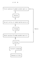
- a latex rubber has hitherto been used to cover the surface of the powder-molded material. That is, a latex rubber has been coated on the powder-molded material, or the powder-molded material has been dipped in a latex rubber solution and dried. The step for covering the surface of the powder-molded material with a latex rubber is repeated a plurality of times, as shown in Fig. 8.
- the rubber in the step of removing the rubber after the isostatic pressing of the latex rubber-covered powder-molded material, it has been necessary to remove the rubber physically (manually) and then dry up the moisture.
- the rubber can be removed by firing in a heat treatment but, in this case, a firing furnace has been necessary.
- the present inventors used a bag-shaped rubber film (which has not been tried hitherto) to cover a powder-molded material and found out that the bag-shaped rubber film can well follow powder-molded materials of complicated shape, i.e. powder-molded materials having notch(es), throughhole(s), dent(s) and/or the like or having a cylindrical shape.
- powder-molded materials having notch(es), throughhole(s), dent(s) and/or the like or having a cylindrical shape.
- a method for subjecting a powder-molded material to isostatic pressing by covering the powder-molded material with a water-non-permeable rubber film, wherein the surface area of the rubber film is larger than the surface area of the powder-molded material.
- the invention is especially advantageous where the molded material has a complicated shape, e.g. its surface has at least one concave region and/or at least one recessed region.
- the inside of the rubber film is preferably made vacuum.
- the powder-molded material is preferably made substantially of a ceramic or a metal.
- the rubber film there can be used, as the rubber film, a commercial ice bag, a commercial semi-translucent rubber tube, etc. as they are.
- the ice bag refers to a bag used for cooling the affected part of a patient by placing ice chips or water therein.
- the rubber film has elasticity, i.e. it has a predetermined size when unstressed, as distinct from a plastically deformable latex.
- the surface area of the rubber film is larger than the surface area of the powder-molded material. This requirement cannot be met in the case of covering the powder-molded material with a latex, because the surface area of the resulting rubber film is equal to the surface area of the powder-molded material.
- the surface area of the rubber film is measured when the rubber film is tightly adhered to the powder-molded material. In view of, for example, the necessity of sealing the rubber film to make the film inside vacuum, the surface area of the rubber film must be larger than the surface area of the powder-molded material.
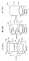
- Fig. 1A, Fig. 1B and Fig. 1C are drawings showing powder-molded materials to which the present invention is applicable.
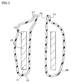
- Fig. 2 is a drawing showing an example of the application of the present invention to a powder-molded material.
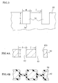
- Fig. 3 is a drawing showing the notches of a powder-molded material to which the present invention is applicable.
- Fig. 4A and Fig.4B are drawings showing the throughholes of a powder-molded material to which the present invention is applicable.
- Fig. 5 is a drawing showing a dynamic blade of gas turbine to which the present invention is applicable.
- Fig. 6 is a drawing showing a static blade of gas turbine to which the present invention is applicable.
- Fig. 7A and Fig. 7B are drawings showing a rotor of turbine to which the present invention is applicable.
- Fig. 7B is a drawing when the rotor is viewed from below
- Fig. 7A is a sectional view of the rotor taken at the P-P' line of Fig. 7B.
- Fig. 8 is a conventional procedure used for covering a powder-molded material with a rubber.
- FIG. 1 shows examples of parts to which the present invention is applicable.
- Each of Fig. 1A, Fig. 1B and Fig. 1C shows a powder-molded material having a cylindrical shape.
- the side wall 10a surrounds a space extending from the end 12a to the end 14a in the axial direction, at the circumference of the space. Both the end 12a and the 14a are open.
- the side wall 10b surrounds a space extending from the end 12b to the end 14b in the axial direction, at the circumference of the space.
- a notch 16b is formed at the end 12b, and a throughhole 17b extending in the diameter direction of the powder-molded material is formed in the side wall 10b.
- Both the end 12b and the end 14b are open. Needless to say, two or more notches or two or more throughholes may be formed.
- the side wall 10c surrounds a space extending from the end 12c to the end 14c in the axial direction, at the circumference of the space.
- a flange 11c and a flange 13c each of ring shape, respectively. Both the end 12c and the end 14c are open.
- the flange 11c and the side wall 10c are in contact at the bent 18c, and the flange 13c and the side wall 10c are in contact at the bent 19c.
- the molded material was subjected to degreasing at 500°C for 10 hours in an atmosphere consisting of 50% by weight of nitrogen and 50% by weight of air.
- the powder-molded material after degreasing was cut to form a notch 16b and a throughhole 17b to obtain a molded material having a shape of Fig. 1B.
- a dent may be formed in place of the throughhole, by cutting the side wall to an extent that no throughhole is formed.
- the portion of the side wall excluding the two ends was cut at the outside to form a flange llc and a flange 13c to obtain a powder-molded material having a shape of Fig. 1C.
- These flanges may be formed by bonding.
- FIG. 2 is a drawing showing a state in which a powder-molded material 20 having a cylindrical shape is covered with a rubber tube 24.
- the rubber tube 24 there was used, for example, a commercial semi-translucent rubber tube having high stretchability and elasticity.
- the powder-molded material 20 was inserted into the rubber tube 24; the rubber tube 24 was folded back, at one end 21 of the powder-molded material 20, into the inside (hollow portion) of the powder-molded material 20; and one end 26 of the rubber tube 24 was taken out from the other end 22 of the powder-molded material 20. Then, the one end 26 and an end 27 corresponding thereto were adhered to each other with a rubber paste.
- Degassing was conducted from other end 26 of the rubber film 24 by the use of a vacuum pump or the like to make vacuum the inside of the rubber film 24. Thereafter, the other end 26 and an end 27 corresponding thereto were adhered to each other with a rubber paste. "Vacuum” is necessary to allow the rubber tube 24 to tightly adhere to the surface of the powder-molded material 20. The adhesion between the end 26 and the end 27 is necessary to avoid the leakage of a pressure medium into the rubber tube 24 during isostatic pressing.
- the rubber tube 24 and the powder-molded material 20 were allowed to stand for about 5 minutes to confirm that there was no leakage from the rubber tube 24. Then, isostatic pressing was conducted at a pressure of 7,000 kgf/cm2. As the pressure medium, there was used a 50:50 (by weight) mixed solution consisting of water and ethylene glycol.
- Comparative Examples 1-3 the production of each powder-molded material, the isostatic pressing step and the sintering step were the same as in Examples 1-3 but the method of rubber film formation was different.
- a latex rubber was brush-coated in a thickness of about 0.2 mm according to the procedure shown in Fig. 8.
- each molded material after isostatic pressing had several discolored areas each of 2-30 mm in diameter. At these areas, the latex rubber was broken and, as a result, the pressure medium penetrated into the molded material. The number of these areas was larger at the ends, notch, throughhole and bents than at the side wall.
- Fig. 3 shows notches 32 formed in a powder-molded material 30. Description is made on the.conditions under which the present invention is favorably applicable to such a powder-molded material 30.
- the height H of each notch 32 is preferably two times or less the width W of the notch, more preferably 1.6 times or less the width W because such a height enables easy adhesion of a rubber film to the bottom 34 of the notch 32.
- the distance I between two adjacent notches 32 is preferably at least the same as the width W of the notch 32, more preferably at least 1.5 times the width W, most preferably at least 2 times the width W.
- Fig. 4A and Fig. 4B show throughholes 42 formed in the side wall 40 of a powder-molded material. Description is made on the conditions under which the present invention is favorably applicable to such a powder-molded material.
- the thickness T of the side wall 40 is preferably 2 times or less the diameter D of each throughhole 42, preferably 1.6 times or less the diameter D, because such a thickness enables easy adhesion of a rubber film to the surface 42S of the through-hole 42.
- the distance I between two adjacent throughholes 42 is preferably at least the same as the diameter D of the throughhole 42, more preferably at least 1.5 times the diameter D, most preferably at least 2 times the diameter D.
- a dynamic blade 50 and a static blade 60 both of gas turbine are shown in Fig. 5.
- the dynamic blade 50 comprises a blade 52, a shroud 54 bonded to the blade 52, and a root 56 bonded to the shroud 54.
- the shroud 54 has a plate shape; on one side of the plate is provided the blade 52; and on other side of the plate is provided the root 56.
- the horizontal section of the blade 52 is streamlined and tapered along the flow of a fluid.
- the static blade 60 comprises a blade 62 and a pair of shrouds 64.
- the horizontal section of the blade 62 is streamlined and tapered along the flow of a fluid.
- a silicon nitride powder There were mixed 100 parts by weight of a silicon nitride powder, 2 parts by weight of a SrCO3 powder, 3 parts by weight of a MgO powder and 3 parts by weight of a CeO2 powder all having an average particle diameter of 1.0 ⁇ m.
- To 100 parts by weight of the resulting compound was added 20 parts by weight of an organic binder.
- the organic binder had a melting point of 62°C and was composed mainly of a paraffin wax.
- the resulting mixture was subjected to injection molding to obtain a powder-molded material 50.
- the powder-molded material was completely buried in an inorganic powder placed in a stainless steel vat.
- the inorganic powder was composed mainly of cordierite, and was dried beforehand and had a water content of not higher than 1%.
- the buried powder-molded material was subjected to degreasing.
- the degreasing step consisted of the following operation. Firstly, the powder-molded material was subjected to temperature elevation from room temperature to 60°C at a rate of 1°C/hr and kept at 60°C for 30 minutes. Then, the resulting material was subjected to temperature elevation from 60°C to 180°C at a rate of 2°C/hr and kept at 180°C for 20 hours. Lastly, the resulting material was subjected to temperature elevation from 180°C to 450°C at a rate of 3°C/hr, kept at 450°C for 10 hours, and cooled from 450°C to room temperature.
- Comparative Examples 4-5 the production of powder-molded material, the isostatic pressing step and the sintering step were conducted in the same manner as in Examples 4-5. However, only the formation of a rubber film was different; that is, a latex rubber was brush-coated according to the procedure shown in Fig. 8. In Comparative Examples 4-5, each powder-molded material after isostatic pressing showed discoloration at several areas (these areas had a diameter of 2-30 mm); at these areas, the latex rubber was broken and a pressure medium penetrated into the powder-molded material. The number of these areas was larger at the edges than at the side wall.
- Example 6 and Comparative Example 6 a turbine rotor shown in Fig. 7A and Fig. 7B were produced by injection molding. The production process was the same as in Examples 4-5 and Comparative Examples 4-5 except for the difference in shape of molded material.
- the turbine rotor 70 is provided about a shaft 79 which is a part independent from the turbine rotor 70.
- the turbine rotor 70 comprises a plurality of blades 72 extending outwardly from the shaft 79 in the shaft diameter direction. Each blade 72 is a curved plate.
- a powder-molded material having a complicated shape for example, a powder-molded material having notch(es), throughhole(s), dent(s) or bent(s) or having a cylindrical shape is covered with a rubber film having a surface area larger than the surface area of the powder-molded material and then subjected to isostatic pressing.
- a rubber film having a surface area larger than the surface area of the powder-molded material is covered with a rubber film having a surface area larger than the surface area of the powder-molded material and then subjected to isostatic pressing.
Landscapes
- Engineering & Computer Science (AREA)
- Mechanical Engineering (AREA)
- Manufacturing & Machinery (AREA)
- Physics & Mathematics (AREA)
- Fluid Mechanics (AREA)
- Chemical & Material Sciences (AREA)
- Ceramic Engineering (AREA)
- Press-Shaping Or Shaping Using Conveyers (AREA)
- Powder Metallurgy (AREA)
Applications Claiming Priority (3)
| Application Number | Priority Date | Filing Date | Title |
|---|---|---|---|
| JP62588/94 | 1994-03-31 | ||
| JP6258894 | 1994-03-31 | ||
| JP6062588A JPH07266090A (ja) | 1994-03-31 | 1994-03-31 | 粉末成形体の等方加圧成形方法 |
Publications (2)
| Publication Number | Publication Date |
|---|---|
| EP0674959A1 true EP0674959A1 (fr) | 1995-10-04 |
| EP0674959B1 EP0674959B1 (fr) | 2001-06-27 |
Family
ID=13204640
Family Applications (1)
| Application Number | Title | Priority Date | Filing Date |
|---|---|---|---|
| EP95302192A Expired - Lifetime EP0674959B1 (fr) | 1994-03-31 | 1995-03-31 | Méthode pour soumettre à un pressage isostatique un élément moulé à partir d'un matériau en poudre |
Country Status (4)
| Country | Link |
|---|---|
| US (1) | US5828942A (fr) |
| EP (1) | EP0674959B1 (fr) |
| JP (1) | JPH07266090A (fr) |
| DE (1) | DE69521449T2 (fr) |
Cited By (2)
| Publication number | Priority date | Publication date | Assignee | Title |
|---|---|---|---|---|
| FR2733314A1 (fr) | 1995-04-20 | 1996-10-25 | Aerospatiale | Dispositif d'allumage pyrotechnique pour un generateur de gaz |
| CN111483171A (zh) * | 2020-04-22 | 2020-08-04 | 四川士达特种炭材有限公司 | 一种等静压石墨筒料成型模具及等静压筒形石墨加工方法 |
Families Citing this family (6)
| Publication number | Priority date | Publication date | Assignee | Title |
|---|---|---|---|---|
| CN102107279A (zh) * | 2009-12-25 | 2011-06-29 | 北京中科三环高技术股份有限公司 | 一种用于粉末冶金工艺的等压方法 |
| CA2840120C (fr) | 2011-07-08 | 2019-01-22 | Xtek Ltd. | Procede de fabrication d'articles multicouches |
| CN103231053B (zh) * | 2013-04-12 | 2015-07-29 | 金堆城钼业股份有限公司 | 冷等静压用制备钼板坯模具 |
| JP6407845B2 (ja) * | 2015-11-27 | 2018-10-17 | 日本碍子株式会社 | アイソスタティック破壊強度試験機、及びアイソスタティック破壊強度試験方法 |
| CN106111983B (zh) * | 2016-06-21 | 2017-12-26 | 金堆城钼业股份有限公司 | 一种可自由收缩的等静压用平装立压式模具及压制方法 |
| DE102017006659A1 (de) * | 2017-07-13 | 2019-01-17 | Forschungszentrum Jülich GmbH | Verfahren zum Sintern von Metallen, nicht oxidischen Keramiken und anderen oxidationsempfindlichen Materialien |
Citations (8)
| Publication number | Priority date | Publication date | Assignee | Title |
|---|---|---|---|---|
| US3235636A (en) * | 1963-04-11 | 1966-02-15 | Hercules Powder Co Ltd | Method of molding teflon |
| CH470256A (de) * | 1965-10-19 | 1969-03-31 | Duriron Co | Beschichteter Gegenstand zur Verwendung unter korrosionsfördernden, chemischen Betriebsverhältnissen |
| DE1608363A1 (de) * | 1967-10-25 | 1970-12-10 | Annawerk Gmbh | Verfahren zum isostatischen Pressen pulverfoermiger insbesondere keramischer Stoffe zu einem Formkoerper |
| EP0133515A2 (fr) * | 1983-08-11 | 1985-02-27 | Mtu Motoren- Und Turbinen-Union MàNchen Gmbh | Procédé de fabrication d'ébauches par compression isostatique à froid |
| US4927600A (en) * | 1985-05-28 | 1990-05-22 | Nippon Kokan Kabushiki Kaisha | Method for molding of powders |
| EP0452936A2 (fr) * | 1990-04-20 | 1991-10-23 | Hutschenreuther AG | Procédé pour la fabrication d'un objet en céramique et dispositif pour le pressage d'une ébauche en céramique |
| DE4117415A1 (de) * | 1990-08-08 | 1992-02-13 | Kobe Steel Ltd | Verfahren zur herstellung einer kapsel fuer den einsatz beim isostatischen pressen |
| US5129813A (en) * | 1991-02-11 | 1992-07-14 | Shepherd G Maury | Embossed vacuum bag, methods for producing and using said bag |
Family Cites Families (7)
| Publication number | Priority date | Publication date | Assignee | Title |
|---|---|---|---|---|
| US3523148A (en) * | 1968-01-04 | 1970-08-04 | Battelle Development Corp | Isostatic pressure transmitting apparatus and method |
| US4588516A (en) * | 1984-12-26 | 1986-05-13 | Schwartz Lenore F | Cleaning liquid and process of using same |
| US4656002A (en) * | 1985-10-03 | 1987-04-07 | Roc-Tec, Inc. | Self-sealing fluid die |
| JPS62297402A (ja) * | 1986-06-17 | 1987-12-24 | Nippon Kokan Kk <Nkk> | 粉体の成形方法 |
| SE460025B (sv) * | 1987-12-18 | 1989-09-04 | Asea Cerama Ab | Saett att framstaella foeremaal av pulverformi gt material genom varm isostatisk pressning i en glasomslutning |
| JPH0324202A (ja) * | 1989-06-22 | 1991-02-01 | Nkk Corp | 金属、セラミックス等の粉体の成形方法 |
| US5445787A (en) * | 1993-11-02 | 1995-08-29 | Friedman; Ira | Method of extruding refractory metals and alloys and an extruded product made thereby |
-
1994
- 1994-03-31 JP JP6062588A patent/JPH07266090A/ja not_active Withdrawn
-
1995
- 1995-03-31 DE DE69521449T patent/DE69521449T2/de not_active Expired - Fee Related
- 1995-03-31 EP EP95302192A patent/EP0674959B1/fr not_active Expired - Lifetime
-
1997
- 1997-03-26 US US08/824,184 patent/US5828942A/en not_active Expired - Fee Related
Patent Citations (8)
| Publication number | Priority date | Publication date | Assignee | Title |
|---|---|---|---|---|
| US3235636A (en) * | 1963-04-11 | 1966-02-15 | Hercules Powder Co Ltd | Method of molding teflon |
| CH470256A (de) * | 1965-10-19 | 1969-03-31 | Duriron Co | Beschichteter Gegenstand zur Verwendung unter korrosionsfördernden, chemischen Betriebsverhältnissen |
| DE1608363A1 (de) * | 1967-10-25 | 1970-12-10 | Annawerk Gmbh | Verfahren zum isostatischen Pressen pulverfoermiger insbesondere keramischer Stoffe zu einem Formkoerper |
| EP0133515A2 (fr) * | 1983-08-11 | 1985-02-27 | Mtu Motoren- Und Turbinen-Union MàNchen Gmbh | Procédé de fabrication d'ébauches par compression isostatique à froid |
| US4927600A (en) * | 1985-05-28 | 1990-05-22 | Nippon Kokan Kabushiki Kaisha | Method for molding of powders |
| EP0452936A2 (fr) * | 1990-04-20 | 1991-10-23 | Hutschenreuther AG | Procédé pour la fabrication d'un objet en céramique et dispositif pour le pressage d'une ébauche en céramique |
| DE4117415A1 (de) * | 1990-08-08 | 1992-02-13 | Kobe Steel Ltd | Verfahren zur herstellung einer kapsel fuer den einsatz beim isostatischen pressen |
| US5129813A (en) * | 1991-02-11 | 1992-07-14 | Shepherd G Maury | Embossed vacuum bag, methods for producing and using said bag |
Cited By (3)
| Publication number | Priority date | Publication date | Assignee | Title |
|---|---|---|---|---|
| FR2733314A1 (fr) | 1995-04-20 | 1996-10-25 | Aerospatiale | Dispositif d'allumage pyrotechnique pour un generateur de gaz |
| CN111483171A (zh) * | 2020-04-22 | 2020-08-04 | 四川士达特种炭材有限公司 | 一种等静压石墨筒料成型模具及等静压筒形石墨加工方法 |
| CN111483171B (zh) * | 2020-04-22 | 2021-04-23 | 四川士达特种炭材有限公司 | 一种使用等静压石墨筒料成型模具生产等静压筒形石墨的加工方法 |
Also Published As
| Publication number | Publication date |
|---|---|
| US5828942A (en) | 1998-10-27 |
| EP0674959B1 (fr) | 2001-06-27 |
| DE69521449D1 (de) | 2001-08-02 |
| DE69521449T2 (de) | 2002-04-11 |
| JPH07266090A (ja) | 1995-10-17 |
Similar Documents
| Publication | Publication Date | Title |
|---|---|---|
| EP0674959B1 (fr) | Méthode pour soumettre à un pressage isostatique un élément moulé à partir d'un matériau en poudre | |
| EP0203789A1 (fr) | Procédé pour le moulage de poudres | |
| US7407622B2 (en) | Method of manufacturing a metal article by powder metallurgy | |
| US20040112564A1 (en) | Methods and apparatus for fabricating turbine engine airfoils | |
| EP0841470A3 (fr) | Méthode de connexion d'une aube à un rotor intégral | |
| US5165591A (en) | Diffusion bonding | |
| EP1085171A3 (fr) | Cavité avec couche thermoprotectrice pour extrémité d'aube de turbine | |
| GB2293629A (en) | A turbomachine aerofoil and a method of production | |
| EP1065344A3 (fr) | Orifices et rainures de refroidissement pour aubes de turbines | |
| JPS55161902A (en) | Ceramic turbine rotor | |
| US4579703A (en) | Method of manufacturing articles of ceramic material | |
| EP0300681A1 (fr) | Moules à façonner et façonnage de corps céramiques par utilisation de ces moules à façonner | |
| US6561247B2 (en) | Method and apparatus for repairing a discrete damaged portion of an article surface | |
| EP0270554B1 (fr) | Procede de fabrication de produits metalliques a partir d'une poudre par compression isostatique a chaud en utilisant des noyaux de ceramique | |
| US4999157A (en) | Method for molding powders | |
| EP0908263A1 (fr) | Procédé de fabrication d'une pièce par soudage par diffusion | |
| EP0443048A4 (en) | Method of producing cemented carbide or cermet alloy | |
| JP2570541B2 (ja) | 鋳造装置 | |
| US4381657A (en) | Method of removing formed parts from a die | |
| KR20010049894A (ko) | 단부 폐쇄형 세라믹 튜브를 제조하기 위한 방법 및 금형 | |
| JP2004174861A (ja) | 有底セラミックス管用成形型およびその製造方法 | |
| US5224644A (en) | Method and apparatus for installation of honeycomb core seals | |
| US4508157A (en) | Self-tapping support for shell molds | |
| US5205470A (en) | Method and apparatus for superplastic forming of hollow parts | |
| RU2355538C2 (ru) | Комплект для изготовления полого механического изделия способом диффузной сварки и сверхпластической формовки и способ изготовления такого изделия |
Legal Events
| Date | Code | Title | Description |
|---|---|---|---|
| PUAI | Public reference made under article 153(3) epc to a published international application that has entered the european phase |
Free format text: ORIGINAL CODE: 0009012 |
|
| AK | Designated contracting states |
Kind code of ref document: A1 Designated state(s): BE DE FR GB |
|
| 17P | Request for examination filed |
Effective date: 19960327 |
|
| 17Q | First examination report despatched |
Effective date: 19981014 |
|
| GRAG | Despatch of communication of intention to grant |
Free format text: ORIGINAL CODE: EPIDOS AGRA |
|
| GRAG | Despatch of communication of intention to grant |
Free format text: ORIGINAL CODE: EPIDOS AGRA |
|
| GRAH | Despatch of communication of intention to grant a patent |
Free format text: ORIGINAL CODE: EPIDOS IGRA |
|
| GRAH | Despatch of communication of intention to grant a patent |
Free format text: ORIGINAL CODE: EPIDOS IGRA |
|
| GRAA | (expected) grant |
Free format text: ORIGINAL CODE: 0009210 |
|
| AK | Designated contracting states |
Kind code of ref document: B1 Designated state(s): BE DE FR GB |
|
| REF | Corresponds to: |
Ref document number: 69521449 Country of ref document: DE Date of ref document: 20010802 |
|
| ET | Fr: translation filed | ||
| REG | Reference to a national code |
Ref country code: GB Ref legal event code: IF02 |
|
| PGFP | Annual fee paid to national office [announced via postgrant information from national office to epo] |
Ref country code: FR Payment date: 20020320 Year of fee payment: 8 |
|
| PGFP | Annual fee paid to national office [announced via postgrant information from national office to epo] |
Ref country code: GB Payment date: 20020321 Year of fee payment: 8 |
|
| PGFP | Annual fee paid to national office [announced via postgrant information from national office to epo] |
Ref country code: BE Payment date: 20020425 Year of fee payment: 8 |
|
| PLBE | No opposition filed within time limit |
Free format text: ORIGINAL CODE: 0009261 |
|
| STAA | Information on the status of an ep patent application or granted ep patent |
Free format text: STATUS: NO OPPOSITION FILED WITHIN TIME LIMIT |
|
| 26N | No opposition filed | ||
| PG25 | Lapsed in a contracting state [announced via postgrant information from national office to epo] |
Ref country code: GB Free format text: LAPSE BECAUSE OF NON-PAYMENT OF DUE FEES Effective date: 20030331 Ref country code: BE Free format text: LAPSE BECAUSE OF NON-PAYMENT OF DUE FEES Effective date: 20030331 |
|
| BERE | Be: lapsed |
Owner name: *NGK INSULATORS LTD Effective date: 20030331 |
|
| GBPC | Gb: european patent ceased through non-payment of renewal fee |
Effective date: 20030331 |
|
| PG25 | Lapsed in a contracting state [announced via postgrant information from national office to epo] |
Ref country code: FR Free format text: LAPSE BECAUSE OF NON-PAYMENT OF DUE FEES Effective date: 20031127 |
|
| REG | Reference to a national code |
Ref country code: FR Ref legal event code: ST |
|
| PGFP | Annual fee paid to national office [announced via postgrant information from national office to epo] |
Ref country code: DE Payment date: 20040324 Year of fee payment: 10 |
|
| PG25 | Lapsed in a contracting state [announced via postgrant information from national office to epo] |
Ref country code: DE Free format text: LAPSE BECAUSE OF NON-PAYMENT OF DUE FEES Effective date: 20051001 |