EP0675261B1 - Porte enroulable avec un vantail de porte souple - Google Patents
Porte enroulable avec un vantail de porte souple Download PDFInfo
- Publication number
- EP0675261B1 EP0675261B1 EP19950102452 EP95102452A EP0675261B1 EP 0675261 B1 EP0675261 B1 EP 0675261B1 EP 19950102452 EP19950102452 EP 19950102452 EP 95102452 A EP95102452 A EP 95102452A EP 0675261 B1 EP0675261 B1 EP 0675261B1
- Authority
- EP
- European Patent Office
- Prior art keywords
- roller
- door
- door leaf
- door according
- slide
- Prior art date
- Legal status (The legal status is an assumption and is not a legal conclusion. Google has not performed a legal analysis and makes no representation as to the accuracy of the status listed.)
- Expired - Lifetime
Links
- 238000004804 winding Methods 0.000 claims description 20
- 239000013013 elastic material Substances 0.000 claims description 5
- 230000008439 repair process Effects 0.000 description 2
- 230000002349 favourable effect Effects 0.000 description 1
- 230000037431 insertion Effects 0.000 description 1
- 238000003780 insertion Methods 0.000 description 1
- 238000009434 installation Methods 0.000 description 1
- 230000006641 stabilisation Effects 0.000 description 1
- 238000011105 stabilization Methods 0.000 description 1
Images


Classifications
-
- E—FIXED CONSTRUCTIONS
- E06—DOORS, WINDOWS, SHUTTERS, OR ROLLER BLINDS IN GENERAL; LADDERS
- E06B—FIXED OR MOVABLE CLOSURES FOR OPENINGS IN BUILDINGS, VEHICLES, FENCES OR LIKE ENCLOSURES IN GENERAL, e.g. DOORS, WINDOWS, BLINDS, GATES
- E06B9/00—Screening or protective devices for wall or similar openings, with or without operating or securing mechanisms; Closures of similar construction
- E06B9/56—Operating, guiding or securing devices or arrangements for roll-type closures; Spring drums; Tape drums; Counterweighting arrangements therefor
- E06B9/58—Guiding devices
- E06B9/581—Means to prevent or induce disengagement of shutter from side rails
-
- E—FIXED CONSTRUCTIONS
- E06—DOORS, WINDOWS, SHUTTERS, OR ROLLER BLINDS IN GENERAL; LADDERS
- E06B—FIXED OR MOVABLE CLOSURES FOR OPENINGS IN BUILDINGS, VEHICLES, FENCES OR LIKE ENCLOSURES IN GENERAL, e.g. DOORS, WINDOWS, BLINDS, GATES
- E06B9/00—Screening or protective devices for wall or similar openings, with or without operating or securing mechanisms; Closures of similar construction
- E06B9/02—Shutters, movable grilles, or other safety closing devices, e.g. against burglary
- E06B9/08—Roll-type closures
- E06B9/11—Roller shutters
- E06B9/13—Roller shutters with closing members of one piece, e.g. of corrugated sheet metal
- E06B2009/135—Horizontal shutter reinforcements
-
- E—FIXED CONSTRUCTIONS
- E06—DOORS, WINDOWS, SHUTTERS, OR ROLLER BLINDS IN GENERAL; LADDERS
- E06B—FIXED OR MOVABLE CLOSURES FOR OPENINGS IN BUILDINGS, VEHICLES, FENCES OR LIKE ENCLOSURES IN GENERAL, e.g. DOORS, WINDOWS, BLINDS, GATES
- E06B9/00—Screening or protective devices for wall or similar openings, with or without operating or securing mechanisms; Closures of similar construction
- E06B9/56—Operating, guiding or securing devices or arrangements for roll-type closures; Spring drums; Tape drums; Counterweighting arrangements therefor
- E06B9/58—Guiding devices
- E06B2009/585—Emergency release to prevent damage of shutter or guiding device
Definitions
- the invention relates to a roller door with a flexible door leaf that is on a top the gate opening rotatably mounted, drivable winding shaft can be wound on the a balancing torque to balance the weight of the hanging door leaf acts, with a quiet attached to the lower end of the door leaf, the two ends are provided with holding pieces on which are mounted on rollers mounted in the floor area running and the door leaf exciting ropes are attached, and with the door opening laterally delimiting, consisting of profiles, the vertical slots into which the side edges of the door leaf protrude.
- a roller door known from DE-A-34 11 664, for example, the one specified at the beginning Kind is that which runs off the winding shaft and is wound onto it Door leaf through at the ends of the bar closing the door leaf downwards, ropes that protrude laterally into the boundary profiles of the roller shutter curtains taut, the one attached to the winding shaft or rotatably mounted on it Winding drums are wound up and unwound, the tension of the Tensioning ropes with torsion springs or pulley-like reeving of the tensioning rope is generated with a bottom block acted upon by spring force and additionally Resilient compensation devices are provided to compensate for the path differences to compensate for the different winding diameters of the wound Roller door and the tensioning cables or - wound on the winding drum straps results.
- a roller door known from DE-C-40 07 280 avoids predetermined breaking points and damage to the door leaf in the event of a start in that the slots in the side profiles gripping ends or guide pieces of the closing the door leaf Last made of a highly elastic material, so that the end areas of the end strip from the damage-free Slits in the side profiles can emerge when the Bar, for example in the event of a start-up, with a corresponding high lateral force is applied.
- the lower one End strip from the side guide slots of the side profiles pushed out, the side edges also kick of the door leaf out of the slots and lose their leadership, so that at least the lower end of the door leaf in uncontrollable Can swing out and flutter.
- the object of the invention is therefore a roller door of the type specified To create the way in which the door leaf closes In the event of impermissibly high transverse forces can swing out without damage and where the gate after one Swing out the end strip quickly and easily again in its normal operating position can be brought without tightening the door leaf can be dispensed with by tension cables acting on the end strip got to.
- this object is achieved with a roller door of the generic type Art solved in that the necessary for leaf tension Tension cables no longer in the rope gate supports Appropriate shots of the end strip are attached instead on holding pieces of the end profile, which are not on the side protrude more into the side profiles.
- each of the profiles in a slide slidably guided vertically for each of the profiles is on its holding part that protrudes the profiles towards the center of the door between top and bottom with one end each Ledge connected holding pieces is bordered such that the Holding part can only emerge laterally between these, and that each tensioning cable is connected to an upper end region of the bar and through a channel or gap in the sled the bottom pulley runs.
- the sled provided in this embodiment is improved the management and stabilization of the final profile and ensures that the pull cables in the side slots of the profiles be performed more wear-free.
- the roller door is the one that closes the door leaf Strip with their two side end areas on the two in the lateral profiles that delimit the door opening Carriage held, the connection inadmissible when it occurs high lateral forces, for example in the event of a start by a vehicle, is lifted without the Release the tension cables from the end bar.
- the roller shutter occur between the ends of the end bar and the slide essentially only vertical forces on by the top and bottom brackets of the bottom bar be transferred to the holding parts of the sled.
- the holding part of the slide is between the fork-shaped holding pieces of the end strip by the Tension rope fixed, which absorbs lateral forces by the fact that it on the side walls of the channel or gap of the sled creates.
- the end bar can be between step out the side profiles that delimit the door opening or swing out, still using the two tension cables remains connected so that an uncontrolled swinging out of the lower area of the door leaf and unwanted flutter is prevented in the event of a crash.
- the door leaf exciting and with the bottom end strip connected ropes are in the channels or columns of the Carriage guided in such a way that even in the case of a lateral Do not push the end strip away from the sled come into contact with the edges of the guide slots and thereby can be damaged.
- each carriage has an upper and one lower stop surface, which are bordered by the holding pieces.
- the carriage can be made from one on opposite sides blocks provided with mutually parallel grooves, the Grooves overlap the profile webs delimiting the slot.
- a such a configuration leads to a particularly simple structure of the carriage, the block preferably made of a plastic with good sliding properties.
- the block can have a gap in the plane of the door leaf be by two disc-shaped connectors or two roles supporting axles is bridged. According to this configuration the block is formed in two parts, the between these parts formed by the two guide slot Parts connecting connectors are bridged, either formed by round sliding surfaces for the tension cables or rollers are.
- the connecting pieces or the axles carrying the rollers are expediently at approximately diagonally opposite one another Corner areas of approximately square or rectangular, the gap delimiting walls of the essentially cuboid block arranged so that good guidance of the tensioning cables is ensured is.
- the holding pieces of the end strip are expediently of mutually parallel, forked connected to the bar, flat profile pieces. In this way, the end bar in the event of inadmissibly high transverse forces from the Slide or slide blocks are pushed off.
- the lower, flat profile piece is made of elastic material.
- This configuration allows for a lateral Pushing the end strip away from the guide block or slide automatically engaging in the operating state again to cause the gate to be fully closed Position is driven, then the sled or block with such a force against the lower profile piece made of elastic Material creates that this is bent upwards and the holding part of the carriage or block in its holding position snaps.
- each Tensioning rope counter to the door leaf on one with the winding shaft connected drum can be wound up and unwound and that between the bottom pulley and the drum the tension cable between two frame-fixed pulleys and the role of one between them arranged bottom block, which is opposite the floor area is tensioned by a tension spring, pulley-like reeving is.
- the roller door according to the invention can be, for example due to a crash of the end profile from the guide sled quickly and easily and even automatically return to its operating state.
- the roller door according to the invention with a device for leaf tension and weight compensation Mistake.
- the Roller door according to the invention for its installation no additional width the gate opening required so that the existing clear width of the gate can be fully used.
- An unwanted and uncontrolled Swinging out and fluttering of the lower part of the Door leaf is avoided after a crash.
- the roller door according to the invention is also characterized in that the lower end strip in the event of a crash regardless of this can safely release, no matter where it hits has been.
- the roller door according to the invention consists of a in the usual way winding shaft with its diameter mounted above the gate opening magnifying winding cylinder 1 on which the flexible door leaf 2 can be wound up.
- On the winding shaft is in the area of the gate opening laterally delimiting profiles, of which in the Figures 2 and 4 to 5 the right profile 5 is shown, a Fixed winding drum 3, on the opposite to the door leaf 2 A tension cable 4 can be wound.
- Each of the two tension cables 4 runs from the winding drum 3 over two deflection rollers mounted on the frame or in the side profiles 5 6, 7 and a roller 8 arranged between them Bottom block via a deflection roller mounted on the base plate 9 10 to its fixed point 11 on the upper holding piece 12, the on the end bar arranged at the lower edge of the door leaf 2 13 is attached.
- the Deflection roller 8 carrying bottom block is the top of one Tension spring 14 attached, the lower end attached to a tab 15 is connected to the axis 16 of the deflection roller 10 is.
- the winding shaft or the winding cylinder 1 for the door leaf 2 is by a counterweight whose strap or tether on one the winding shaft attached drum is wound or by a tension spring in the winding direction with a compensating torque charged, but taking into account that of the Tension rope on the winding shaft is exerted so large that the door leaf is wholly or partially wound on the winding cylinder if, in the event of a power failure, the brake of the Drive motor is vented.
- Each of the side profiles 5 of the goal frame has in its a surface pointing towards the center of the door Slot 18, which is limited by the webs 19, 20 of the profile 5 becomes.
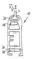
- this slot is a roughly cuboid Block 21 made of plastic with a low coefficient of friction performed, provided on opposite sides with grooves 22, 23 in which the webs 19, 20 of the side profile 5 engage.
- the block 21 is in its vertical center plane with a Gap 24 provided by two disc-like connectors 25, 26 is bridged, the two also approximately cuboid Connect the holding parts 27, 28 of the block 21 together.
- the disc-like connectors 25, 26 are in the 2 apparent manner approximately diagonally to the rectangular or square walls of the block delimiting the gap 24 21 arranged.
- the holding pieces 12, 32 which consist of flat profile pieces and the ends of the bar or the end profile 13 in the manner shown in FIG. 2 protrude fork-like, fastened by screws.
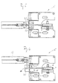
- the out Fig. 5 apparent operating position summarize the final profile 13 protruding holding pieces 12, 32 the guide slot 18 protruding part of the block 21 fork-shaped between them a.
- the holding pieces 12, 32 avoided by the block 21 in that the tensioning cable 4 is held and centered on the gap 24 delimiting, inner side walls of the block 21 creates.
- the end profile 13 thereby clicks off the guide block 21 from that the holding pieces 12, 32 of this in the 6 apparent manner with the entrainment of the tensioning cable 4th be pushed away.
- the rope 4 slips over the upper, rounded one Edge of the gap 24 in the one shown in FIGS. 2 and 6 Way, without limiting the guide gap 18 Profile bars to connect.
- the lower holding piece 32 can consist of elastic material, so that after disengaging the end profile 13 an automatic It can be latched in that the gate is in the direction is moved to its closed position.
- the upper one lays down Edge of the block 21 against the lower outside of the flexible Stop piece 32 in such a way that it is bent upwards until the holding block 21 snaps into its operating position slips over this.
- the lower holding piece can be used accordingly be shorter, with a corresponding Game of the holding block between the holding pieces 12, 32 is provided becomes.
Landscapes
- Engineering & Computer Science (AREA)
- Structural Engineering (AREA)
- Architecture (AREA)
- Civil Engineering (AREA)
- Operating, Guiding And Securing Of Roll- Type Closing Members (AREA)
- Blinds (AREA)
- Gates (AREA)
Claims (10)
- Porte enroulable avec un vantail de porte flexible (2) qui peut être enroulé sur un arbre d'enroulement (1) apte à être entraíné, logé à rotation au-dessus de l'ouverture de porte et sur lequel, pour équilibrer le poids du vantail de porte s'étendant vers le bas, agit un couple d'équilibrage, avec une baguette (13) fixée à l'extrémité inférieure du vantail de porte (2) dont les deux extrémités sont pourvues de pièces de retenue (12, 32) sur lesquelles sont fixées des câbles (4) passant sur des rouleaux (10) logés dans la zone de fond et tendant le vantail de porte (2) et avec des parties latérales (5) délimitant latéralement l'ouverture de porte, constituées de profilés qui présentent des fentes verticales (18) dans lesquelles font saillie les bords latéraux du vantail de porte (2), caractérisé en ce que les pièces de retenue (12, 32) ne font pas saillie dans les parties latérales (5).
- Porte enroulable selon la revendication 1, caractérisé en ce qu'il est guidé de manière déplaçable verticalement dans chacune des parties latérales (5) un chariot (21) qui est entouré à ses pièces de retenue (27, 28) faisant saillie sur les parties latérales (5) vers le milieu de la porte, entre des pièces de retenue (12, 32) supérieure et inférieure reliées respectivement à une extrémité de la baguette (13) de telle sorte que les pièces de retenue (12, 32) peuvent glisser respectivement sortir seulement dans la direction latérale de la pièce de retenue et en ce que chaque câble tendeur (4) est relié par une zone d'extrémité supérieure de la baguette (13) et s'étend à travers un canal ou fente (24) du chariot (21) vers le rouleau de renvoi (10) côté fond.
- Porte enroulable selon la revendication 1 ou 2, caractérisée en ce que chaque chariot (21) possède une surface de butée supérieure et inférieure qui sont enserrées par les pièces de retenue (12, 32).
- Porte enroulable selon l'une des revendications 1 à 3, caractérisée en ce que le chariot est constitué d'un bloc (21) pourvu aux côtés opposés de rainures parallèles l'une à l'autre (22, 23) et en ce que les rainures (22, 23) passent sur les baguettes profilées (19, 20) passant sur la fente (18).
- Porte enroulable selon l'une des revendications 1 à 4, caractérisée en ce que le bloc (21) est pourvu dans le plan du vantail (2) d'une fente (24) sur laquelle passent deux pièces de liaison (25, 26) en forme de disque ou deux axes portant les rouleaux.
- Porte enroulable selon l'une des revendications 1 à 5, caractérisée en ce que les pièces de liaison (25, 26) ou axes sont disposés dans des zones angulaires opposées à peu près diagonalement l'une à l'autre des parois à peu près carrées ou rectangulaires, délimitant la fente (24) du bloc (21) sensiblement parallélépipède.
- Porte enroulable selon l'une des revendications 1 à 6, caractérisée en ce que les pièces de retenue (12, 32) sont constituées de pièces profilées plates, parallèles l'une à l'autre, reliées à la baguette (13) à la manière d'une fourche.
- Porte enroulable selon l'une des revendications 1 à 7, caractérisée en ce que le câble tendeur (4) est relié respectivement à la pièce profilée supérieure plate (12).
- Porte enroulable selon l'une des revendications 1 à 8, caractérisée en ce que la pièce profilée inférieure plate (32) est réalisée en matière élastique.
- Porte enroulable selon l'une des revendications 1 à 9, caractérisée en ce que chaque câble tendeur (4) peut être enroulé sur ou déroulé, suivant un déplacement opposé au vantail de porte (2), d'un tambour (3) relié à l'arbre d'enroulement (1) et en ce que, entre le rouleau de renvoi côté fond (10) et le tambour (3), le câble tendeur (4) passe à la manière d'un palan entre deux rouleaux de renvoi (6, 7) logés de manière solidaire au châssis et le rouleau (8) d'une bouteille inférieure disposée entre ceux-ci qui est tendue par rapport à la zone de fond par un ressort de traction (14).
Applications Claiming Priority (4)
| Application Number | Priority Date | Filing Date | Title |
|---|---|---|---|
| DE4410770 | 1994-03-28 | ||
| DE4410770 | 1994-03-28 | ||
| DE4414524 | 1994-04-26 | ||
| DE4414524A DE4414524C2 (de) | 1994-03-28 | 1994-04-26 | Rolltor mit einem flexiblen Torblatt |
Publications (2)
| Publication Number | Publication Date |
|---|---|
| EP0675261A1 EP0675261A1 (fr) | 1995-10-04 |
| EP0675261B1 true EP0675261B1 (fr) | 1998-05-06 |
Family
ID=25935163
Family Applications (1)
| Application Number | Title | Priority Date | Filing Date |
|---|---|---|---|
| EP19950102452 Expired - Lifetime EP0675261B1 (fr) | 1994-03-28 | 1995-02-21 | Porte enroulable avec un vantail de porte souple |
Country Status (3)
| Country | Link |
|---|---|
| EP (1) | EP0675261B1 (fr) |
| DE (1) | DE4447598C1 (fr) |
| ES (1) | ES2115279T3 (fr) |
Families Citing this family (6)
| Publication number | Priority date | Publication date | Assignee | Title |
|---|---|---|---|---|
| DE29714616U1 (de) * | 1997-08-14 | 1997-11-20 | Schieffer Tor- und Schutzsysteme GmbH, 59557 Lippstadt | Rolltor mit einem flexiblen Torblatt |
| DE29716966U1 (de) | 1997-09-22 | 1997-11-13 | Schieffer Tor- und Schutzsysteme GmbH, 59557 Lippstadt | Rolltor mit einem flexiblen Torblatt |
| DE29818095U1 (de) | 1998-10-09 | 1999-03-25 | Bauelemente Renate Wielath, 88094 Oberteuringen | Schnelllauftor |
| JP4509664B2 (ja) * | 2003-07-30 | 2010-07-21 | 株式会社東芝 | 蒸気タービン発電設備 |
| DE102012111611A1 (de) | 2012-11-29 | 2014-06-05 | Efaflex Inzeniring D.O.O. | Rolltor mit einem Torblatt in Gestalt eines flexiblen Behangs |
| CN110306916A (zh) * | 2019-07-25 | 2019-10-08 | 东莞柏翠科门窗家具有限公司 | 一种卷闸门 |
Family Cites Families (5)
| Publication number | Priority date | Publication date | Assignee | Title |
|---|---|---|---|---|
| DE3429781A1 (de) * | 1984-04-02 | 1985-10-10 | Schieffer GmbH & Co KG, 4780 Lippstadt | Rolltor mit einem flexiblen torblatt |
| US5141044A (en) * | 1991-01-25 | 1992-08-25 | Asi Technologies, Inc. | Breakaway roll-up door |
| US5139074A (en) * | 1991-04-03 | 1992-08-18 | Kelley Company Inc. | Industrial door having flexible and releasable beam |
| DE4242430C2 (de) * | 1991-12-23 | 1995-01-05 | Norbert Lamsfuss | Rolltor |
| US5222541A (en) * | 1992-07-22 | 1993-06-29 | Kelley Company, Inc. | Industrial door having releasable beam and tension bracket retention mechanism |
-
1994
- 1994-04-26 DE DE4447598A patent/DE4447598C1/de not_active Expired - Fee Related
-
1995
- 1995-02-21 EP EP19950102452 patent/EP0675261B1/fr not_active Expired - Lifetime
- 1995-02-21 ES ES95102452T patent/ES2115279T3/es not_active Expired - Lifetime
Also Published As
| Publication number | Publication date |
|---|---|
| DE4447598C1 (de) | 1997-03-06 |
| EP0675261A1 (fr) | 1995-10-04 |
| ES2115279T3 (es) | 1998-06-16 |
Similar Documents
| Publication | Publication Date | Title |
|---|---|---|
| DE2341328C3 (de) | Rolltor | |
| DE3241924C2 (de) | Vorrichtung zum Führen von flexiblen Versorgungsleitungen | |
| EP0701649B1 (fr) | Leve-vitre manuel a cable | |
| DE3905224A1 (de) | Rolltor | |
| DE4324641A1 (de) | Rolltorkonstruktion | |
| EP0172351B1 (fr) | Dispositif antichute | |
| WO1999015754A1 (fr) | Porte roulante avec vantail flexible | |
| DE4007280C2 (fr) | ||
| DE3843917C2 (fr) | ||
| DE4006212C2 (de) | Jalousie | |
| DE4447598C1 (de) | Rolltor mit flexiblem Torblatt | |
| DE4024666A1 (de) | Sektionaltor | |
| EP0899413A1 (fr) | Volet roulant, en particulier pour plan incliné | |
| CH635164A5 (de) | Raffstore. | |
| DE3526745C2 (fr) | ||
| DE4414524C2 (de) | Rolltor mit einem flexiblen Torblatt | |
| DE19949329C2 (de) | Schnellauftor | |
| DE29903517U1 (de) | Tor | |
| EP1366259B1 (fr) | Porte sectionnee | |
| DE69215844T2 (de) | Jalousie mit einfacher steuerung | |
| DE19600949C2 (de) | Rolladen für Fenster oder Türen | |
| DE2853460C2 (de) | Wickelvorrichtung zum Bewegen eines Trägerbandes für einen Reklame- oder Anzeigegegenstand | |
| DE3741744A1 (de) | Tor mit einem in seitlichen fuehrungen verschieblichen torblatt | |
| DE10236869A1 (de) | Raffstore mit Wendelager | |
| CH653095A5 (en) | Gatherable lamellar blind with an arrangement for approximately horizontal alignment of the lowest lamella |
Legal Events
| Date | Code | Title | Description |
|---|---|---|---|
| PUAI | Public reference made under article 153(3) epc to a published international application that has entered the european phase |
Free format text: ORIGINAL CODE: 0009012 |
|
| AK | Designated contracting states |
Kind code of ref document: A1 Designated state(s): BE DE ES FR GB IT NL |
|
| 17P | Request for examination filed |
Effective date: 19951116 |
|
| 17Q | First examination report despatched |
Effective date: 19970430 |
|
| RAP1 | Party data changed (applicant data changed or rights of an application transferred) |
Owner name: SCHIEFFER TOR- UND SCHUTZSYSTEME GMBH |
|
| GRAG | Despatch of communication of intention to grant |
Free format text: ORIGINAL CODE: EPIDOS AGRA |
|
| GRAG | Despatch of communication of intention to grant |
Free format text: ORIGINAL CODE: EPIDOS AGRA |
|
| GRAH | Despatch of communication of intention to grant a patent |
Free format text: ORIGINAL CODE: EPIDOS IGRA |
|
| GRAH | Despatch of communication of intention to grant a patent |
Free format text: ORIGINAL CODE: EPIDOS IGRA |
|
| GRAA | (expected) grant |
Free format text: ORIGINAL CODE: 0009210 |
|
| AK | Designated contracting states |
Kind code of ref document: B1 Designated state(s): BE DE ES FR GB IT NL |
|
| REF | Corresponds to: |
Ref document number: 59502082 Country of ref document: DE Date of ref document: 19980610 |
|
| REG | Reference to a national code |
Ref country code: ES Ref legal event code: FG2A Ref document number: 2115279 Country of ref document: ES Kind code of ref document: T3 |
|
| GBT | Gb: translation of ep patent filed (gb section 77(6)(a)/1977) |
Effective date: 19980616 |
|
| ITF | It: translation for a ep patent filed | ||
| ET | Fr: translation filed | ||
| PLBE | No opposition filed within time limit |
Free format text: ORIGINAL CODE: 0009261 |
|
| STAA | Information on the status of an ep patent application or granted ep patent |
Free format text: STATUS: NO OPPOSITION FILED WITHIN TIME LIMIT |
|
| 26N | No opposition filed | ||
| REG | Reference to a national code |
Ref country code: GB Ref legal event code: IF02 |
|
| PGFP | Annual fee paid to national office [announced via postgrant information from national office to epo] |
Ref country code: NL Payment date: 20140208 Year of fee payment: 20 |
|
| PGFP | Annual fee paid to national office [announced via postgrant information from national office to epo] |
Ref country code: FR Payment date: 20140211 Year of fee payment: 20 Ref country code: ES Payment date: 20140113 Year of fee payment: 20 Ref country code: IT Payment date: 20140109 Year of fee payment: 20 Ref country code: BE Payment date: 20140214 Year of fee payment: 20 |
|
| PGFP | Annual fee paid to national office [announced via postgrant information from national office to epo] |
Ref country code: GB Payment date: 20140219 Year of fee payment: 20 |
|
| PGFP | Annual fee paid to national office [announced via postgrant information from national office to epo] |
Ref country code: DE Payment date: 20140417 Year of fee payment: 20 |
|
| REG | Reference to a national code |
Ref country code: DE Ref legal event code: R071 Ref document number: 59502082 Country of ref document: DE |
|
| REG | Reference to a national code |
Ref country code: DE Ref legal event code: R071 Ref document number: 59502082 Country of ref document: DE |
|
| REG | Reference to a national code |
Ref country code: NL Ref legal event code: V4 Effective date: 20150221 |
|
| REG | Reference to a national code |
Ref country code: GB Ref legal event code: PE20 Expiry date: 20150220 |
|
| REG | Reference to a national code |
Ref country code: ES Ref legal event code: FD2A Effective date: 20150428 |
|
| PG25 | Lapsed in a contracting state [announced via postgrant information from national office to epo] |
Ref country code: GB Free format text: LAPSE BECAUSE OF EXPIRATION OF PROTECTION Effective date: 20150220 |
|
| PG25 | Lapsed in a contracting state [announced via postgrant information from national office to epo] |
Ref country code: ES Free format text: LAPSE BECAUSE OF EXPIRATION OF PROTECTION Effective date: 20150222 |