EP0675336A1 - Projectile, notamment balle non létale - Google Patents
Projectile, notamment balle non létale Download PDFInfo
- Publication number
- EP0675336A1 EP0675336A1 EP95400677A EP95400677A EP0675336A1 EP 0675336 A1 EP0675336 A1 EP 0675336A1 EP 95400677 A EP95400677 A EP 95400677A EP 95400677 A EP95400677 A EP 95400677A EP 0675336 A1 EP0675336 A1 EP 0675336A1
- Authority
- EP
- European Patent Office
- Prior art keywords
- projectile
- product
- housing
- skirt
- impact
- Prior art date
- Legal status (The legal status is an assumption and is not a legal conclusion. Google has not performed a legal analysis and makes no representation as to the accuracy of the status listed.)
- Granted
Links
Images

Classifications
-
- F—MECHANICAL ENGINEERING; LIGHTING; HEATING; WEAPONS; BLASTING
- F42—AMMUNITION; BLASTING
- F42B—EXPLOSIVE CHARGES, e.g. FOR BLASTING, FIREWORKS, AMMUNITION
- F42B12/00—Projectiles, missiles or mines characterised by the warhead, the intended effect, or the material
- F42B12/02—Projectiles, missiles or mines characterised by the warhead, the intended effect, or the material characterised by the warhead or the intended effect
- F42B12/36—Projectiles, missiles or mines characterised by the warhead, the intended effect, or the material characterised by the warhead or the intended effect for dispensing materials; for producing chemical or physical reaction; for signalling ; for transmitting information
- F42B12/40—Projectiles, missiles or mines characterised by the warhead, the intended effect, or the material characterised by the warhead or the intended effect for dispensing materials; for producing chemical or physical reaction; for signalling ; for transmitting information of target-marking, i.e. impact-indicating type
-
- F—MECHANICAL ENGINEERING; LIGHTING; HEATING; WEAPONS; BLASTING
- F42—AMMUNITION; BLASTING
- F42B—EXPLOSIVE CHARGES, e.g. FOR BLASTING, FIREWORKS, AMMUNITION
- F42B12/00—Projectiles, missiles or mines characterised by the warhead, the intended effect, or the material
- F42B12/02—Projectiles, missiles or mines characterised by the warhead, the intended effect, or the material characterised by the warhead or the intended effect
- F42B12/36—Projectiles, missiles or mines characterised by the warhead, the intended effect, or the material characterised by the warhead or the intended effect for dispensing materials; for producing chemical or physical reaction; for signalling ; for transmitting information
-
- F—MECHANICAL ENGINEERING; LIGHTING; HEATING; WEAPONS; BLASTING
- F42—AMMUNITION; BLASTING
- F42B—EXPLOSIVE CHARGES, e.g. FOR BLASTING, FIREWORKS, AMMUNITION
- F42B12/00—Projectiles, missiles or mines characterised by the warhead, the intended effect, or the material
- F42B12/02—Projectiles, missiles or mines characterised by the warhead, the intended effect, or the material characterised by the warhead or the intended effect
- F42B12/36—Projectiles, missiles or mines characterised by the warhead, the intended effect, or the material characterised by the warhead or the intended effect for dispensing materials; for producing chemical or physical reaction; for signalling ; for transmitting information
- F42B12/46—Projectiles, missiles or mines characterised by the warhead, the intended effect, or the material characterised by the warhead or the intended effect for dispensing materials; for producing chemical or physical reaction; for signalling ; for transmitting information for dispensing gases, vapours, powders or chemically-reactive substances
Definitions
- the present invention relates to a projectile, in particular a bullet, intended to put an opponent out of action without major risk of fatal injury.
- Such projectiles are used by the police to put an end to unrest on the public highway during agitated demonstrations or riots.
- projectiles intended to be used in front of demonstrators are also known.
- projectiles which, fired towards the crowd but towards the sky, release suffocating or irritating gases, causing the dispersal of the demonstrators.
- the impact-induced effect is not always sufficient to stop the attacker, especially if he has a protective shield.
- Projectiles releasing gases have the disadvantage of releasing their substance in a very large space, due to the nature of the shooting and therefore of inconvenience a large number of people being on the premises among which sometimes include people not involved in the disturbances, or even the police when they regain possession of the ground previously occupied by the demonstrators at the time of the shooting and whose air is heavily loaded with gases.
- the present invention therefore aims to combine in a single projectile the interests of the two types of projectiles mentioned above by eliminating the undesirable effect due to the excessive dispersion of gases.
- the subject of the invention is therefore a projectile or bullet characterized in that it comprises a body comprising a receiving housing containing an active fluid on a living or non-living target and means allowing the release of this fluid during the impact of the projectile on its target, the body of the projectile comprising a propulsion motor as well as, along its length, a portion of smaller diameter followed by a shoulder forming a braking plane perpendicular to the direction of movement of the projectile.
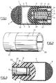
- FIG 1 there is shown a self-propelling projectile according to the invention comprising a body 1, formed by a nose 2 with a rounded tip, extended by a cylindrical skirt 3, itself connected to a base 4 carrying a motor 5
- the cylindrical skirt 3 and the base 4 are two separate pieces fitted one on the other, but it is also conceivable that the cylindrical skirt 3 came integrally with the base 4.
- the skirt 3 defines a housing 6 between the nose 2 and the base 4. In this housing 6 there is a capsule 7 containing an irritant liquid 8.
- the thickness of the walls of the capsule 7 is sufficiently small to allow rapid rupture of the walls as soon as the irritant liquid 8 is subjected to a significant pressure, thus causing its release.
- the nose 2 has a portion in the form of a warhead 9 made of a material capable of absorbing, by deforming, part of the impact energy (rubber for example).
- This warp-shaped part is completed by a solid cylindrical element 10 made of rigid plastic material bonded to its flat base.
- the base 4 of generally cylindrical shape has a guide wall 11 allowing it to fit into the skirt 3 to thereby form a compact assembly which, with the nose 2, forms the body 1 of the ball.
- the base 4 On its rear face, the base 4 includes a central well 12 in which the motor 5 is housed.
- the base 4 is made by plastic molding and has recessed parts 13 in order to reduce the total mass.
- the motor 5 has a conventional constitution for self-propelled projectiles. It consists of a cylindrical body 14 and a nozzle 15, both made of metal.
- the cylindrical body of the engine can also be constituted by the walls of an axial bore made in the base 4.
- the nozzle is crimped, glued or machined on the body 14.
- the nozzle 15 has at its center, flush with the rear face of the base 4, a primer 16 with percussion or electric depending on the type of launcher used.
- the cylindrical body 14 of the motor 5 thus formed contains a propellant powder 17 connected to the primer 16 by conventional suitable means.
- a volume compensation piece 18 is added to the engine according to the quantity of powder required.
- the number, the inclination and the diameter of the holes of the nozzle 15, the mass and the nature of the powder, as well as the size of the compensation piece 18 are adapted according to the desired characteristics of the projectile.
- Such a projectile is intended to be fired from an individual weapon comprising a barrel adapted to the caliber of the projectile and a device for firing the primer.
- a projectile according to the invention does not have a shell and therefore leaves no element in the weapon after being fired.
- skirt 3 of the previously described projectile made of a plastic material comprises, along generators, breaking initiators 19 leading to a single end 20 of the skirt. Once the projectile has been assembled, these rupture primers are opposite the housing 6 containing the liquid 8. The part 21 of the skirt devoid of rupture primers is intended to receive the base 4.
- the cylindrical element 10 then compresses the fluid 8 contained in the capsule 7 against the base 4, causing the rupture of the walls of the capsule and therefore the release of the fluid contained therein.
- FIG. 3 a projectile of the same type as that of FIG. 1 is shown schematically and differing from it only by its base 4.
- the cylindrical base 4 has a portion 30 cylindrical of smaller diameter. This portion 30 is extended on one side by a flared portion of increasing diameter 31 towards the front and is limited towards the rear by a stabilization braking plane 32.
- the rear of the base extending beyond of the braking plane 32 comprises a chamfer 33.
- This particular structure is adapted to ensure braking of the ball, the latter offering the air means resistant to advancement. Furthermore, the braking plane 32 ensures the stabilization of the ball.
- the skirt 40 has come in one piece with the warp-shaped part 41 of the nose 2, thus forming a warhead 42 made of a deformable material (rubber for example) and forming with the base 4 engaged in the skirt 40, as seen in Figure 4, a housing 43 containing the irritant liquid.
- the skirt 50 made in one piece with the rib-shaped part 41 of the nose 2 comprises a portion 51 in the form of a compressible bellows. This bellows is intended to absorb part of the energy during the impact.
- This portion 51 in the form of a compressible bellows defines with the base engaged in the skirt (not shown) the housing for the fluid which is therefore opposite said bellows.
- FIG. 6 shows a projectile according to another embodiment of the invention.
- a tube 59 of the same axis as the base 4 and the skirt 3 extends from the base 4 in the housing 6 intended to contain the fluid.
- a circular groove 60 is arranged on the base 4 to allow the tube to be embedded in the base. Glue can be added during assembly to ensure the seal between the tube and the base.
- the housing 6 intended to contain the fluid has a toroidal shape and contains a spongy material 61 intended to contain the irritant liquid.
- a nose 62 forming a plug, has a hemispherical projecting end. It is provided with an axial piston 63 engaged in the tube 59.
- Guide means 64 integrally formed with the nose 62 allow the nose to penetrate the skirt 3 along the main axis of the projectile during an impact.
- the guide means 64 comprise a cylindrical part cooperating with the end of the skirt 3 and have, in the vicinity of the hemispherical part of the nose, a flared portion 65 whose maximum diameter is greater than the inside diameter of the skirt 3. During the impact, the nose forming a plug enters the skirt 3 and the flared part 65 of the nose promotes the bursting of this skirt.
- the piston 63 enters the tube 60 which, subjected to the overpressure of the air it contains, bursts, thus promoting the dispersion of the fluid 8 contained in the capsule 7 through the skirt 3, itself torn according to its breaking points.
- the fluid can also be placed directly in the housing 6 delimited by the skirt 3, the nose 2 and the base 4.
- the propulsion engine always remains integral with the projectile. Therefore, this type of projectile leaves no element in the launcher such as a shell. It can be fired from a launcher of very simple design, easy to use, very handy and not requiring the use of rifle type riot for example, with magazine and ejector of casing.
- the propulsion motor can be of the self-propelled type, this gives the projectile a speed increasing over part of its trajectory.
- the projectile thus reaches its full effectiveness at a determined firing distance. In the first part of the trajectory, the effect is therefore attenuated, which gives it security at the start of the trajectory.
- the propulsion engine can be of the impulse type; this gives the projectile a determined initial speed which is then almost constant.
- the projectile thus has the same efficiency and the same safety over its entire useful trajectory.
- the projectile can be used on a living target, but also on a fixed or mobile non-living target, in particular when the fluid contained in the projectile is a marking fluid.
- the fluid can be replaced by any type of product, a powder for example.
Landscapes
- Engineering & Computer Science (AREA)
- Chemical & Material Sciences (AREA)
- Combustion & Propulsion (AREA)
- General Engineering & Computer Science (AREA)
- Toys (AREA)
- Agricultural Chemicals And Associated Chemicals (AREA)
- Aiming, Guidance, Guns With A Light Source, Armor, Camouflage, And Targets (AREA)
- Polyurethanes Or Polyureas (AREA)
Abstract
Description
- La présente invention concerne un projectile, notamment une balle, destinée à mettre hors de combat un adversaire sans risque majeur de blessure mortelle.
- De tels projectiles sont utilisés par les forces de l'ordre pour faire cesser les troubles sur la voie publique lors de manifestations agitées ou d'émeutes.
- On connaît actuellement dans l'état de la technique des projectiles en caoutchouc ou matériaux équivalents qui sont destinés à être tirés en tir tendu sur des manifestants afin de les neutraliser. Les charges propulsives sont adaptées pour que l'impact du projectile sur le manifestant ne crée que des meurtrissures sans danger pour la vie de celui-ci.
- On connaît également d'autres types de projectiles destinés à être utilisés face à des manifestants. En particulier, des projectiles qui, tirés en direction de la foule mais vers le ciel, libèrent des gaz suffocants ou irritants, provoquant la dispersion des manifestants.
- Avec le premier type de projectile, l'effet induit par le choc n'est pas toujours suffisant pour stopper l'assaillant surtout s'il dispose d'un bouclier de protection.
- Les projectiles libèrant des gaz présentent eux l'inconvénient de libérer leur substance dans un espace très large, du fait de la nature du tir et donc d'incommoder un grand nombre de personnes se trouvant sur les lieux parmi lesquelles figurent parfois des personnes non impliquées dans les troubles, ou bien même les forces de l'ordre lorsqu'elles reprennent possession du terrain occupé précédemment par les manifestants au moment du tir et dont l'air est largement chargé des gaz.
- La présente invention a donc pour but de conjuguer en un même projectile les intérêts des deux types de projectiles précédemment évoqués en supprimant l'effet indésirable dû à la dispersion excessive des gaz.
- Elle vise donc à créer un projectile permettant de créer un effet d'impact lors du choc du projectile sur sa cible et un effet neutralisant par libération d'un fluide irritant au voisinage du point d'impact.
- L'invention a donc pour objet un projectile ou balle caractérisé en ce qu'il comprend un corps comportant un logement de réception contenant un fluide actif sur une cible vivante ou non et des moyens permettant la libération de ce fluide lors de l'impact du projectile sur sa cible, le corps du projectile comportant un moteur de propulsion ainsi que, sur sa longueur, une portion de plus faible diamètre suivie d'un épaulement formant un plan de freinage perpendiculaire à la direction de déplacement du projectile.
- Suivant d'autres caractéristiques :
- le corps comporte des amorces de rupture facilitant son éclatement lors d'un impact pour permettre la libération du produit contenu dans le logement ;
- les amorces de rupture sont constituées par des entailles pratiquées suivant des génératrices du corps ;
- le corps comporte dans son nez des moyens d'absorption d'une partie de l'énergie lors du choc d'impact ;
- le corps comprend une pièce massive déformable en forme générale d'ogive prolongée par une jupe délimitant le logement pour le produit et reliée à son tour à une embase ;
- les amorces de rupture sont ménagées dans la jupe au moins en regard du logement de réception contenant le produit ;
- la jupe du corps comporte au moins une partie en forme de soufflet compressible pour absorber une partie de l'énergie lors du choc d'impact ;
- le nez du corps forme un bouchon évasé dont une partie fait saillie à l'extérieur de la jupe et dont une partie engagée dans la jupe amorce la rupture du corps lors de l'impact ;
- le logement de réception contenant le produit comporte une capsule formant capacité contenant le produit ;
- le logement de réception contenant le produit comporte un matériau spongieux apte à contenir du fluide ;
- le nez du corps est réalisé en un matériau contondant comme du caoutchouc ;
- le logement de réception contenant le produit comporte suivant son axe un tube solidaire de l'embase du projectile et fermé en regard de cette embase et le nez comporte un piston adapté pour coopérer avec le tube et provoquer l'éclatement de celui-ci par surpression de l'air emprisonné dans le tube lors de l'impact, facilitant ainsi la libération du produit contenu dans le logement ;
- L'invention sera mieux comprise et d'autres avantages apparaîtront à la lecture de la description qui va suivre, donnée uniquement à titre d'exemple et faite en se référant aux dessins annexés, sur lesquels :
- la figure 1 est une vue en coupe d'un projectile suivant l'invention.
- la figure 2 est une vue en perspective d'un exemple de corps de projectile portant des amorces de rupture suivant l'invention ;
- les figures 3, 4 et 6 sont des vues en coupe d'autres modes de réalisation du projectile suivant l'invention ;
- la figure 5 est une vue en coupe d'un exemple de corps suivant l'invention portant un soufflet compressible.
- Sur la figure 1, on a représenté un projectile autopropulseur suivant l'invention comprenant un corps 1, formé d'un nez 2 à pointe arrondie, prolongé d'une jupe 3 cylindrique, reliée elle-même à une embase 4 portant un moteur 5. Ici, la jupe cylindrique 3 et l'embase 4 sont deux pièces distinctes emboîtées l'une sur l'autre mais on peut également concevoir que la jupe cylindrique 3 soit venue de matière avec l'embase 4.
- La jupe 3 délimite un logement 6 compris entre le nez 2 et l'embase 4. Dans ce logement 6 se trouve une capsule 7 contenant un liquide irritant 8.
- L'épaisseur des parois de la capsule 7 est suffisamment faible pour permettre la rupture rapide des parois dès que le liquide irritant 8 est soumis à une pression importante, provoquant ainsi sa libération.
- Le nez 2 présente une partie en forme d'ogive 9 réalisée en un matériau capable d'absorber en se déformant une partie de l'énergie de choc (caoutchouc par exemple). Cette partie en forme d'ogive est complétée par un élément cylindrique plein 10 en matière plastique rigide collé sur sa base plane.
- L'embase 4 de forme générale cylindrique comporte une paroi de guidage 11 permettant son emboîtement dans la jupe 3 pour former ainsi un ensemble compact qui avec le nez 2 forme le corps 1 de la balle. Sur sa face arrière, l'embase 4 comporte un puits central 12 dans lequel est logé le moteur 5.
- L'embase 4 est réalisée par moulage en matière plastique et présente des parties évidées 13 afin d'en diminuer la masse totale.
- Le moteur 5 possède une constitution classique pour les projectiles autopropulsés. Il est constitué d'un corps cylindrique 14 et d'une tuyère 15, tous deux réalisés en métal.
- Le corps cylindrique du moteur peut également être constitué par les parois d'un alésage axial pratiqué dans l'embase 4.
- La tuyère est sertie, collée ou usinée sur le corps 14.
- La tuyère 15 comporte en son centre, affleurant la face arrière de l'embase 4, une amorce 16 à percussion ou électrique suivant le type de lanceur utilisé.
- Le corps cylindrique 14 du moteur 5 ainsi formé contient une poudre propulsive 17 reliée à l'amorce 16 par des moyens appropriés classiques. Une pièce de compensation volumique 18 est ajoutée dans le moteur en fonction de la quantité de poudre nécessaire.
- Le nombre, l'inclinaison et le diamètre des trous de la tuyère 15, la masse et la nature de la poudre, ainsi que la taille de la pièce de compensation 18 sont adaptés en fonction des caractéristiques désirées du projectile.
- Un tel projectile est destiné à être tiré à partir d'une arme individuelle comportant un canon adapté au calibre du projectile et un dispositif de mise à feu de l'amorce. Comme on le voit sur la figure 1, un tel projectile suivant l'invention ne comporte pas de douille et ne laisse donc aucun élément dans l'arme après avoir été tiré.
- Sur la figure 2, on peut voir un mode de réalisation de la jupe 3 du projectile précédemment décrit. La jupe 3 constituée d'un matériau plastique comporte suivant des génératrices des amorces de rupture 19 débouchant sur une seule extrémité 20 de la jupe. Une fois le projectile assemblé, ces amorces de rupture sont en regard du logement 6 contenant le liquide 8. La partie 21 de la jupe dépourvue d'amorces de rupture est destinée à recevoir l'embase 4.
- Lors du choc d'un projectile tel que décrit, avec une cible, le nez 2 s'écrase contre la cible, absorbant par déformation une partie de l'énergie de la balle.
- L'élément cylindrique 10 vient alors comprimer le fluide 8 contenu dans la capsule 7 contre l'embase 4, provoquant la rupture des parois de la capsule et donc la libération du fluide contenu dans celle-ci.
- La jupe 3 sous l'effet du choc se déchire en tulipe suivant les amorces de rupture 19, afin de libérer vers l'extérieur le fluide 8 irritant contenu dans le logement 6.
- Sur la figure 3, on a représenté schématiquement un projectile de même type que celui de la figure 1 et ne différant de celui-ci que par son embase 4. En effet, sur la figure 3, l'embase cylindrique 4 comporte une portion 30 cylindrique de plus faible diamètre. Cette portion 30 est prolongée d'un côté par une portion évasée de diamètre croissant 31 vers l'avant et est limitée vers l'arrière par un plan de freinage de stabilisation 32. L'arrière de l'embase s'étendant au-delà du plan de freinage 32 comporte un chanfrein 33.
- Cette structure particulière est adaptée pour assurer un freinage de la balle, celle-ci offrant à l'air des moyens résistant à l'avancement. Par ailleurs, le plan de freinage 32 assure la stabilisation de la balle.
- On peut, en fonction des besoins, moduler les dimensions et les formes du profil extérieur du corps de la balle.
- Sur la figure 4, on peut voir un projectile semblable à celui décrit en référence à la figure 1, certains éléments n'ayant pas été représentés.
- Sur cette figure, la jupe 40 est venue de matière avec la partie en forme d'ogive 41 du nez 2, formant ainsi une ogive 42 réalisée en un matériau déformable (caoutchouc par exemple) et forme avec l'embase 4 engagée dans la jupe 40, comme on le voit sur la figure 4, un logement 43 contenant le liquide irritant.
- Suivant un autre mode de réalisation de l'invention, représenté sur la figure 5, la jupe 50 venue de matière avec la partie en forme d'ogive 41 du nez 2 comprend une portion 51 en forme de soufflet compressible. Ce soufflet est destiné à absorber une partie de l'énergie lors du choc.
- Cette portion 51 en forme de soufflet compressible définit avec l'embase engagée dans la jupe (non représentée) le logement pour le fluide qui est donc en regard dudit soufflet.
- Sur la figure 6, est représenté un projectile selon un autre mode de réalisation de l'invention. Un tube 59 de même axe que l'embase 4 et la jupe 3 s'étend depuis l'embase 4 dans le logement 6 destiné à contenir le fluide. Une gorge circulaire 60 est aménagée sur l'embase 4 pour permettre l'encastrement du tube dans l'embase. Une colle peut être ajoutée lors du montage pour assurer l'étanchéité entre le tube et l'embase.
- Dans ce cas, la logement 6 destiné à contenir le fluide a une forme toroïdale et contient un matériau spongieux 61 destiné à contenir le liquide irritant.
- Un nez 62, formant bouchon, présente une extrémité en saillie hémisphérique. Il est muni d'un piston axial 63 engagé dans le tube 59.
- Des moyens de guidage 64 venus de matière avec le nez 62 permettent au nez de pénétrer dans la jupe 3 suivant l'axe principal du projectile lors d'un choc.
- Les moyens de guidage 64 comportent une partie cylindrique coopérant avec l'extrémité de la jupe 3 et présentent au voisinage de la partie hémisphérique du nez une portion évasée 65 dont le diamètre maximum est supérieur au diamètre intérieur de la jupe 3. Lors du choc, le nez formant bouchon pénètre dans la jupe 3 et la partie évasée 65 du nez favorise l'éclatement de cette jupe.
- Lors du choc, le piston 63 pénètre dans le tube 60 qui, soumis à la surpression de l'air qu'il contient, éclate favorisant ainsi la dispersion du fluide 8 contenu dans la capsule 7 au travers de la jupe 3, elle-même déchirée suivant ses amorces de rupture.
- La description qui précède présente des projectiles dans lesquels on a placé un fluide irritant. Celui-ci peut bien sûr être remplacé par tout autre fluide par exemple un fluide marqueur.
- Dans chacun des modes de réalisation décrits ci-dessus, on peut utiliser soit une capsule soit un corps spongieux pour contenir le fluide irritant 8.
- Le fluide peut également être placé directement dans le logement 6 délimité par la jupe 3, le nez 2 et l'embase 4.
- De même, on peut imaginer un projectile non autopropulsif suivant l'invention. Il suffit pour cela de supprimer le moteur de l'embase du projectile et de munir le projectile ainsi obtenu d'une douille contenant de la poudre et un moyen de mise à feu de cette poudre.
- Cependant, le fait que le projectile porte le moteur de propulsion conduit à un certain nombre d'avantages.
- En particulier, le moteur de propulsion reste toujours solidaire du projectile. De ce fait, ce type de projectile ne laisse aucun élément dans le lanceur comme par exemple une douille. Il peut être tiré à partir d'un lanceur de conception très simple, facile d'utilisation, très maniable et ne nécessitant pas l'emploi de fusil de type anti-émeutes par exemple, avec chargeur et éjecteur de douille.
- De plus, le moteur de propulsion peut être de type autopropulsé, ceci confère au projectile une vitesse croissante sur une partie de sa trajectoire. Le projectile atteint ainsi toute son efficacité à une distance de tir déterminée. Dans la première partie de la trajectoire, l'effet est donc atténué, ce qui lui confère une sécurité en début de trajectoire.
- Par ailleurs, le moteur de propulsion peut être de type impulsionnel ; ceci confère au projectile une vitesse initiale déterminée qui est ensuite quasi constante. Le projectile présente ainsi la même efficacité et la même sécurité sur l'ensemble de sa trajectoire utile.
- Le projectile peut être utilisé sur une cible vivante, mais également sur une cible non vivante fixe ou mobile, en particulier lorsque le fluide contenu dans le projectile est un fluide marqueur.
- Par ailleurs, le fluide peut être remplacé par tout type de produit, une poudre par exemple.
Claims (12)
Applications Claiming Priority (2)
| Application Number | Priority Date | Filing Date | Title |
|---|---|---|---|
| FR9403852A FR2718229B1 (fr) | 1994-03-31 | 1994-03-31 | Projectile, notamment balle non létale . |
| FR9403852 | 1994-03-31 |
Publications (2)
| Publication Number | Publication Date |
|---|---|
| EP0675336A1 true EP0675336A1 (fr) | 1995-10-04 |
| EP0675336B1 EP0675336B1 (fr) | 1999-09-15 |
Family
ID=9461650
Family Applications (1)
| Application Number | Title | Priority Date | Filing Date |
|---|---|---|---|
| EP95400677A Expired - Lifetime EP0675336B1 (fr) | 1994-03-31 | 1995-03-27 | Projectile, notamment balle non létale |
Country Status (7)
| Country | Link |
|---|---|
| US (1) | US5565649A (fr) |
| EP (1) | EP0675336B1 (fr) |
| AT (1) | ATE184698T1 (fr) |
| CA (1) | CA2145950C (fr) |
| DE (1) | DE69512118T2 (fr) |
| ES (1) | ES2139157T3 (fr) |
| FR (1) | FR2718229B1 (fr) |
Cited By (5)
| Publication number | Priority date | Publication date | Assignee | Title |
|---|---|---|---|---|
| DE19528348C1 (de) * | 1995-08-02 | 1996-11-07 | Daimler Benz Aerospace Ag | Geschoß zum Vorgehen gegen lebende Ziele ohne letales Risiko für diese |
| RU2154799C1 (ru) * | 2000-02-03 | 2000-08-20 | Государственное унитарное предприятие "Государственное научно-производственное предприятие "Сплав" | Вращающаяся ракета |
| RU2177598C1 (ru) * | 2001-04-18 | 2001-12-27 | Федеральный научно-производственный центр "НИИ прикладной химии" | Способ поражения боевой частью заливного снаряжения, боевая часть заливного снаряжения и способ ее снаряжения |
| EP2520899A3 (fr) * | 2011-05-06 | 2014-12-17 | Rheinmetall Waffe Munition GmbH | Projectile de caoutchouc ou à impulsion |
| FR3090084A1 (fr) * | 2018-12-18 | 2020-06-19 | Securengy | Projectile pour armes a feu ou air comprime pour emport liquide ou pulverulent |
Families Citing this family (54)
| Publication number | Priority date | Publication date | Assignee | Title |
|---|---|---|---|---|
| US6142056A (en) * | 1995-12-18 | 2000-11-07 | U.T. Battelle, Llc | Variable thrust cartridge |
| US7194960B2 (en) * | 1996-11-18 | 2007-03-27 | Pepperball Technologies, Inc. | Non-lethal projectiles for delivering an inhibiting substance to a living target |
| US5965839A (en) * | 1996-11-18 | 1999-10-12 | Jaycor | Non-lethal projectile for delivering an inhibiting substance to a living target |
| US20030047105A1 (en) * | 1996-11-18 | 2003-03-13 | Jaycor Tactical Systems, Inc. | Non-lethal projectile systems |
| US6393992B1 (en) | 1996-11-18 | 2002-05-28 | Jaycor Tactical Systems, Inc. | Non-lethal projectile for delivering an inhibiting substance to a living target |
| US6543365B1 (en) | 1996-11-18 | 2003-04-08 | Jaycor Tactical Systems, Inc. | Non-lethal projectile systems |
| FR2768504B3 (fr) * | 1997-09-12 | 1999-11-26 | Isher | Projectile a deformation controlee |
| NO307154B1 (no) * | 1998-08-17 | 2000-02-14 | Raufoss Tech As | Ívelsesrakett for roekutvikling |
| US6230630B1 (en) | 1999-03-10 | 2001-05-15 | Perfect Circle Paintball, Inc. | Aerodynamic projectiles and methods of making the same |
| CN1081786C (zh) * | 1999-06-10 | 2002-03-27 | 谢蕴 | 枪炮弹 |
| AU1568601A (en) * | 1999-08-11 | 2001-03-05 | Tony Zanti | Nonlethal projectile launched by a lethal projectile discharged from a firearm |
| US7086337B2 (en) * | 2000-09-28 | 2006-08-08 | Klein John M | Non-lethal projectile ammunition |
| US20020178960A1 (en) * | 2000-10-19 | 2002-12-05 | Ramaswamy Alba Lalitha | Generation non-lethal and lethal projectiles for arms |
| DE10303106B4 (de) * | 2002-01-29 | 2013-01-10 | Ruag Munition | Barrikadenbrecher |
| US7089863B1 (en) * | 2002-06-11 | 2006-08-15 | The United States Of America As Represented By The Secretary Of The Army | Non-Lethal cartridges with dense powder ballast |
| US7526998B2 (en) * | 2003-02-10 | 2009-05-05 | Pepperball Technologies, Inc. | Stabilized non-lethal projectile systems |
| US6860207B1 (en) * | 2003-08-22 | 2005-03-01 | Thomas W. Robertson | Compressible shot shell |
| US20050066849A1 (en) * | 2003-09-29 | 2005-03-31 | Kapeles John A. | Frangible non-lethal projectile |
| US7350465B2 (en) * | 2003-12-29 | 2008-04-01 | Neil Keegstra | Extended range less lethal projectile |
| US7278358B2 (en) * | 2004-01-22 | 2007-10-09 | Pdt Tech, Llc. | Non-lethal marking bullet for related training cartridges |
| DE102004017466A1 (de) * | 2004-04-08 | 2005-11-03 | Nico-Pyrotechnik Hanns-Jürgen Diederichs GmbH & Co. KG | Geschoss mit Markierung des Auftreffpunktes |
| US7426888B2 (en) * | 2004-09-02 | 2008-09-23 | T&P Game Recovery, Llc | Firearm ammunition for tracking wounded prey |
| USD610224S1 (en) * | 2005-04-14 | 2010-02-16 | Mactavish William Dirk | Serrated sabot |
| DE102005031749A1 (de) * | 2005-07-07 | 2007-01-11 | Rheinmetall Waffe Munition Gmbh | Nicht letales, programmier- und/oder tempierbares Geschoss |
| DE102005060882B3 (de) * | 2005-12-20 | 2007-05-24 | Bundesrepublik Deutschland, vertreten durch das Bundesministerium der Verteidigung, vertreten durch das Bundesamt für Wehrtechnik und Beschaffung | Nichtletales Impulsgeschoss |
| US7966937B1 (en) | 2006-07-01 | 2011-06-28 | Jason Stewart Jackson | Non-newtonian projectile |
| US7373887B2 (en) * | 2006-07-01 | 2008-05-20 | Jason Stewart Jackson | Expanding projectile |
| US20080134927A1 (en) * | 2006-10-05 | 2008-06-12 | Skellern Michael J | Projectile with dispersible contents and method of manufacturing the same |
| US20080178728A1 (en) * | 2007-01-25 | 2008-07-31 | Kapeles John A | Frangible non-lethal projectile |
| KR20100016159A (ko) * | 2007-04-01 | 2010-02-12 | 시큐리티 디바이시스 인터내셔널 아이엔씨. | 비-살상 발사체 |
| DE102007034546A1 (de) * | 2007-07-20 | 2009-01-22 | Rheinmetall Waffe Munition Gmbh | Zielmarkierungsmunition |
| US7926424B1 (en) * | 2007-09-05 | 2011-04-19 | Quintana Mauricio F | Liquid mist tracer for shotgun ammunition |
| EP2232191A4 (fr) | 2007-09-18 | 2013-03-27 | Pepperball Technologies Inc | Systèmes, procédés et appareils destinés à être utilisés dans une distribution de poudre à effets inhibants |
| IL186114A (en) * | 2007-09-20 | 2013-08-29 | Rafael Advanced Defense Sys | Bullet to Kill equipped with a rocket cruiser |
| US7743708B1 (en) * | 2008-04-30 | 2010-06-29 | Lawrence James R | Non lethal spread projectile |
| SG177631A1 (en) | 2009-07-21 | 2012-02-28 | Kevin Michael Sullivan | Impact locating day and night marker for a projectile |
| US8286557B2 (en) * | 2009-08-03 | 2012-10-16 | Alliant Techsystems Inc. | Projectiles for marking targets, methods of manufacturing the same, and methods of utilizing the same |
| NO2464944T3 (fr) | 2009-08-11 | 2018-05-12 | ||
| DE102010025829A1 (de) | 2010-07-01 | 2012-01-05 | Rheinmetall Waffe Munition Gmbh | Leitwerkstabilisiertes Impulsgeschoss |
| DE102011100791B4 (de) | 2011-05-06 | 2015-04-09 | Rheinmetall Waffe Munition Gmbh | Impulsgeschoss |
| US9200877B1 (en) * | 2012-05-02 | 2015-12-01 | Darren Rubin | Biological active bullets, systems, and methods |
| USD765215S1 (en) * | 2015-01-22 | 2016-08-30 | United Tactical Systems, Llc | Non-lethal projectile |
| US9766049B2 (en) | 2015-01-27 | 2017-09-19 | United Tactical Systems, Llc | Aerodynamic projectile |
| WO2016130190A2 (fr) * | 2015-02-06 | 2016-08-18 | Darren Rubin | Balles biologiques actives, systèmes, et procédés associés |
| US10060715B1 (en) * | 2015-05-28 | 2018-08-28 | Desi A Davis | Nonlethal incapacitating bullet |
| US11209254B2 (en) * | 2016-03-09 | 2021-12-28 | Msato, Llc | Pellet shaped marking round for air rifles and pistols |
| US10690463B2 (en) | 2017-01-12 | 2020-06-23 | Vista Outdoor Operations Llc | Extended range bullet |
| US11639845B2 (en) * | 2017-08-24 | 2023-05-02 | Nostromo, Llc | Mid-body marking projectile |
| WO2019040873A1 (fr) | 2017-08-24 | 2019-02-28 | Nostromo, Llc | Projectile de marquage à corps intermédiaire |
| US20200109931A1 (en) * | 2018-09-07 | 2020-04-09 | CSP Consulting, LLC | Non-Lethal Projectile Construction and Launcher |
| US11248891B2 (en) * | 2019-06-12 | 2022-02-15 | Insights International Holdings, Llc | Ordnance ballistics deployment system |
| WO2022154851A2 (fr) * | 2020-11-04 | 2022-07-21 | Nostromo, Llc | Projectile de marquage de corps central |
| US11940253B2 (en) | 2021-06-09 | 2024-03-26 | Cyalume Technologies, Inc. | Projectile payload for training ammunition with multi-spectral output |
| US11644289B2 (en) * | 2021-09-28 | 2023-05-09 | Insights International Holdings, Llc | Ordnance delivery system using a protective housing as an antenna |
Citations (6)
| Publication number | Priority date | Publication date | Assignee | Title |
|---|---|---|---|---|
| US1671364A (en) * | 1926-12-10 | 1928-05-29 | Gangnes Arnt | Firearm cartridge |
| US3037454A (en) * | 1961-04-19 | 1962-06-05 | Wendell M Young | Livestock marking bullet |
| US3782286A (en) * | 1970-11-12 | 1974-01-01 | E Richie | Non-lethal projectile and launcher therefor |
| US3865038A (en) * | 1973-07-13 | 1975-02-11 | Irwin R Barr | Deterrent ammunition projectile |
| GB2213572A (en) * | 1988-01-11 | 1989-08-16 | Oded Grinberg | Projectile |
| US5086703A (en) * | 1991-02-05 | 1992-02-11 | Klein John M | Universal projectile ammunition |
Family Cites Families (12)
| Publication number | Priority date | Publication date | Assignee | Title |
|---|---|---|---|---|
| CA542590A (fr) * | 1957-06-25 | H. Konvalin Laurence | Plombs entraines par poudre a fusil | |
| US2112758A (en) * | 1935-05-04 | 1938-03-29 | Blacker Latham Valenti Stewart | Projectile |
| US2408252A (en) * | 1942-12-23 | 1946-09-24 | Kaiser Cargo Inc | Ammunition |
| US2444283A (en) * | 1943-11-06 | 1948-06-29 | Curtiss Wright Corp | Projectile |
| US3429263A (en) * | 1967-04-17 | 1969-02-25 | James B Snyder | Marking projectile and method of use |
| US3911824A (en) * | 1973-07-13 | 1975-10-14 | Aai Corp | Deterrent ammunition projectile |
| US3995550A (en) * | 1975-12-03 | 1976-12-07 | The United States Of America As Represented By The Secretary Of The Army | Apparatus for stabilizing a liquid filled artillery projectile |
| US4419936A (en) * | 1980-04-11 | 1983-12-13 | The United States Of America As Represented By The Secretary Of The Army | Ballistic projectile |
| DE3408476A1 (de) * | 1984-03-08 | 1985-09-12 | Rheinmetall GmbH, 4000 Düsseldorf | Vollkalibriges uebungsgeschoss |
| US5018449A (en) * | 1988-09-20 | 1991-05-28 | Eidson Ii Edward W | Paint dispersing training grenade |
| US4932329A (en) * | 1989-08-11 | 1990-06-12 | Logie Glenn S | Simulated hand grenade with marking means |
| US5035183A (en) * | 1990-03-12 | 1991-07-30 | David Luxton | Frangible nonlethal projectile |
-
1994
- 1994-03-31 FR FR9403852A patent/FR2718229B1/fr not_active Expired - Fee Related
-
1995
- 1995-03-27 EP EP95400677A patent/EP0675336B1/fr not_active Expired - Lifetime
- 1995-03-27 ES ES95400677T patent/ES2139157T3/es not_active Expired - Lifetime
- 1995-03-27 DE DE69512118T patent/DE69512118T2/de not_active Expired - Fee Related
- 1995-03-27 AT AT95400677T patent/ATE184698T1/de active
- 1995-03-30 US US08/413,824 patent/US5565649A/en not_active Expired - Fee Related
- 1995-03-30 CA CA002145950A patent/CA2145950C/fr not_active Expired - Fee Related
Patent Citations (6)
| Publication number | Priority date | Publication date | Assignee | Title |
|---|---|---|---|---|
| US1671364A (en) * | 1926-12-10 | 1928-05-29 | Gangnes Arnt | Firearm cartridge |
| US3037454A (en) * | 1961-04-19 | 1962-06-05 | Wendell M Young | Livestock marking bullet |
| US3782286A (en) * | 1970-11-12 | 1974-01-01 | E Richie | Non-lethal projectile and launcher therefor |
| US3865038A (en) * | 1973-07-13 | 1975-02-11 | Irwin R Barr | Deterrent ammunition projectile |
| GB2213572A (en) * | 1988-01-11 | 1989-08-16 | Oded Grinberg | Projectile |
| US5086703A (en) * | 1991-02-05 | 1992-02-11 | Klein John M | Universal projectile ammunition |
Cited By (5)
| Publication number | Priority date | Publication date | Assignee | Title |
|---|---|---|---|---|
| DE19528348C1 (de) * | 1995-08-02 | 1996-11-07 | Daimler Benz Aerospace Ag | Geschoß zum Vorgehen gegen lebende Ziele ohne letales Risiko für diese |
| RU2154799C1 (ru) * | 2000-02-03 | 2000-08-20 | Государственное унитарное предприятие "Государственное научно-производственное предприятие "Сплав" | Вращающаяся ракета |
| RU2177598C1 (ru) * | 2001-04-18 | 2001-12-27 | Федеральный научно-производственный центр "НИИ прикладной химии" | Способ поражения боевой частью заливного снаряжения, боевая часть заливного снаряжения и способ ее снаряжения |
| EP2520899A3 (fr) * | 2011-05-06 | 2014-12-17 | Rheinmetall Waffe Munition GmbH | Projectile de caoutchouc ou à impulsion |
| FR3090084A1 (fr) * | 2018-12-18 | 2020-06-19 | Securengy | Projectile pour armes a feu ou air comprime pour emport liquide ou pulverulent |
Also Published As
| Publication number | Publication date |
|---|---|
| ATE184698T1 (de) | 1999-10-15 |
| EP0675336B1 (fr) | 1999-09-15 |
| ES2139157T3 (es) | 2000-02-01 |
| FR2718229B1 (fr) | 1996-06-21 |
| FR2718229A1 (fr) | 1995-10-06 |
| US5565649A (en) | 1996-10-15 |
| DE69512118D1 (de) | 1999-10-21 |
| CA2145950A1 (fr) | 1995-10-01 |
| DE69512118T2 (de) | 2000-02-03 |
| CA2145950C (fr) | 2002-01-29 |
Similar Documents
| Publication | Publication Date | Title |
|---|---|---|
| EP0675336B1 (fr) | Projectile, notamment balle non létale | |
| EP2923171B1 (fr) | Projectile gyrostabilise projetant une charge utile | |
| EP0106263B1 (fr) | Projectile explosif perforant encartouché | |
| CH688946A5 (fr) | Dispositif de capture, notamment pour arme à feu. | |
| EP0572643B1 (fr) | Tube douille pour grenade a fusil pouvant retenir les fragments de la balle | |
| US20140230680A1 (en) | Less than lethal projectile and ammunition | |
| EP2297545A1 (fr) | Munition non letale | |
| EP0910245B1 (fr) | Artifice de lutte contre le peril aviaire | |
| CN210773705U (zh) | 一种尾翼稳定型破障催泪弹 | |
| EP0030051B1 (fr) | Grenade à fusil | |
| RU2095742C1 (ru) | Пуля травматического действия | |
| FR2936044A1 (fr) | Mecanisme pneumatique pour arme-jouet, lancant des billes de peinture ou de plastique de faible poids, actionne par une munition pyrotechnique specifique | |
| WO2005098346A1 (fr) | Dispositif emetteur de rayonnement notamment infrarouge | |
| BE1003971A3 (fr) | Perfectionnements aux projectiles. | |
| FR2719373A1 (fr) | Dispositif de propulsion à portées variables pour grenade anti-émeutes. | |
| BE1001908A3 (fr) | Projectile pour le tir a portee reduite. | |
| WO2019025576A1 (fr) | Munitions d`entraînement pour armes à feu, procédé de fabrication et méthode d`utilisation | |
| EP3022519B1 (fr) | Projectile, en particulier munition, pour lanceur de defense | |
| FR3151653A3 (fr) | Projectile de neutralisation temporaire | |
| EP0448422B1 (fr) | Grenade d'exercise tirable par fusil et système d'instruction au tir de grenades à fusil | |
| FR2937123A1 (fr) | Munition de controle des foules a effet non letal | |
| FR3090084A1 (fr) | Projectile pour armes a feu ou air comprime pour emport liquide ou pulverulent | |
| FR2992409A1 (fr) | Munition non letale a portee accrue | |
| EP1160532A2 (fr) | Magasin du type tambour comportant des munitions pour armes de neutralisation | |
| FR2547407A1 (fr) | Projectile d'exercice pour artillerie a freinage de trajectoire et marquage d'impact |
Legal Events
| Date | Code | Title | Description |
|---|---|---|---|
| PUAI | Public reference made under article 153(3) epc to a published international application that has entered the european phase |
Free format text: ORIGINAL CODE: 0009012 |
|
| AK | Designated contracting states |
Kind code of ref document: A1 Designated state(s): AT BE CH DE DK ES FR GB GR IT LI NL SE |
|
| 17P | Request for examination filed |
Effective date: 19950914 |
|
| 17Q | First examination report despatched |
Effective date: 19970530 |
|
| GRAG | Despatch of communication of intention to grant |
Free format text: ORIGINAL CODE: EPIDOS AGRA |
|
| GRAG | Despatch of communication of intention to grant |
Free format text: ORIGINAL CODE: EPIDOS AGRA |
|
| GRAH | Despatch of communication of intention to grant a patent |
Free format text: ORIGINAL CODE: EPIDOS IGRA |
|
| GRAH | Despatch of communication of intention to grant a patent |
Free format text: ORIGINAL CODE: EPIDOS IGRA |
|
| GRAA | (expected) grant |
Free format text: ORIGINAL CODE: 0009210 |
|
| RAP1 | Party data changed (applicant data changed or rights of an application transferred) |
Owner name: ETIENNE LACROIX TOUS ARTIFICES S.A. |
|
| AK | Designated contracting states |
Kind code of ref document: B1 Designated state(s): AT BE CH DE DK ES FR GB GR IT LI NL SE |
|
| PG25 | Lapsed in a contracting state [announced via postgrant information from national office to epo] |
Ref country code: NL Free format text: LAPSE BECAUSE OF FAILURE TO SUBMIT A TRANSLATION OF THE DESCRIPTION OR TO PAY THE FEE WITHIN THE PRESCRIBED TIME-LIMIT Effective date: 19990915 Ref country code: GR Free format text: LAPSE BECAUSE OF NON-PAYMENT OF DUE FEES Effective date: 19990915 Ref country code: AT Free format text: LAPSE BECAUSE OF FAILURE TO SUBMIT A TRANSLATION OF THE DESCRIPTION OR TO PAY THE FEE WITHIN THE PRESCRIBED TIME-LIMIT Effective date: 19990915 |
|
| REF | Corresponds to: |
Ref document number: 184698 Country of ref document: AT Date of ref document: 19991015 Kind code of ref document: T |
|
| REG | Reference to a national code |
Ref country code: CH Ref legal event code: EP |
|
| REF | Corresponds to: |
Ref document number: 69512118 Country of ref document: DE Date of ref document: 19991021 |
|
| ITF | It: translation for a ep patent filed | ||
| PG25 | Lapsed in a contracting state [announced via postgrant information from national office to epo] |
Ref country code: DK Free format text: LAPSE BECAUSE OF FAILURE TO SUBMIT A TRANSLATION OF THE DESCRIPTION OR TO PAY THE FEE WITHIN THE PRESCRIBED TIME-LIMIT Effective date: 19991215 |
|
| GBT | Gb: translation of ep patent filed (gb section 77(6)(a)/1977) |
Effective date: 19991217 |
|
| NLV1 | Nl: lapsed or annulled due to failure to fulfill the requirements of art. 29p and 29m of the patents act | ||
| REG | Reference to a national code |
Ref country code: ES Ref legal event code: FG2A Ref document number: 2139157 Country of ref document: ES Kind code of ref document: T3 |
|
| PG25 | Lapsed in a contracting state [announced via postgrant information from national office to epo] |
Ref country code: LI Free format text: LAPSE BECAUSE OF NON-PAYMENT OF DUE FEES Effective date: 20000331 Ref country code: CH Free format text: LAPSE BECAUSE OF NON-PAYMENT OF DUE FEES Effective date: 20000331 |
|
| PLBE | No opposition filed within time limit |
Free format text: ORIGINAL CODE: 0009261 |
|
| STAA | Information on the status of an ep patent application or granted ep patent |
Free format text: STATUS: NO OPPOSITION FILED WITHIN TIME LIMIT |
|
| 26N | No opposition filed | ||
| REG | Reference to a national code |
Ref country code: CH Ref legal event code: PL |
|
| REG | Reference to a national code |
Ref country code: GB Ref legal event code: IF02 |
|
| PGFP | Annual fee paid to national office [announced via postgrant information from national office to epo] |
Ref country code: SE Payment date: 20030219 Year of fee payment: 9 |
|
| PGFP | Annual fee paid to national office [announced via postgrant information from national office to epo] |
Ref country code: DE Payment date: 20030312 Year of fee payment: 9 |
|
| PGFP | Annual fee paid to national office [announced via postgrant information from national office to epo] |
Ref country code: ES Payment date: 20030314 Year of fee payment: 9 |
|
| PGFP | Annual fee paid to national office [announced via postgrant information from national office to epo] |
Ref country code: GB Payment date: 20030321 Year of fee payment: 9 |
|
| PGFP | Annual fee paid to national office [announced via postgrant information from national office to epo] |
Ref country code: BE Payment date: 20030328 Year of fee payment: 9 |
|
| PG25 | Lapsed in a contracting state [announced via postgrant information from national office to epo] |
Ref country code: GB Free format text: LAPSE BECAUSE OF NON-PAYMENT OF DUE FEES Effective date: 20040327 |
|
| PG25 | Lapsed in a contracting state [announced via postgrant information from national office to epo] |
Ref country code: SE Free format text: LAPSE BECAUSE OF NON-PAYMENT OF DUE FEES Effective date: 20040328 |
|
| PG25 | Lapsed in a contracting state [announced via postgrant information from national office to epo] |
Ref country code: ES Free format text: LAPSE BECAUSE OF NON-PAYMENT OF DUE FEES Effective date: 20040329 |
|
| PG25 | Lapsed in a contracting state [announced via postgrant information from national office to epo] |
Ref country code: BE Free format text: LAPSE BECAUSE OF NON-PAYMENT OF DUE FEES Effective date: 20040331 |
|
| BERE | Be: lapsed |
Owner name: S.A. ETIENNE *LACROIX TOUS ARTIFICES Effective date: 20040331 |
|
| PG25 | Lapsed in a contracting state [announced via postgrant information from national office to epo] |
Ref country code: DE Free format text: LAPSE BECAUSE OF NON-PAYMENT OF DUE FEES Effective date: 20041001 |
|
| EUG | Se: european patent has lapsed | ||
| GBPC | Gb: european patent ceased through non-payment of renewal fee |
Effective date: 20040327 |
|
| PG25 | Lapsed in a contracting state [announced via postgrant information from national office to epo] |
Ref country code: IT Free format text: LAPSE BECAUSE OF NON-PAYMENT OF DUE FEES Effective date: 20050327 |
|
| REG | Reference to a national code |
Ref country code: ES Ref legal event code: FD2A Effective date: 20040329 |
|
| PGFP | Annual fee paid to national office [announced via postgrant information from national office to epo] |
Ref country code: FR Payment date: 20140331 Year of fee payment: 20 |