EP0675630B1 - Vorrichtung zum Fördern von abgetastetem Material - Google Patents
Vorrichtung zum Fördern von abgetastetem Material Download PDFInfo
- Publication number
- EP0675630B1 EP0675630B1 EP95104458A EP95104458A EP0675630B1 EP 0675630 B1 EP0675630 B1 EP 0675630B1 EP 95104458 A EP95104458 A EP 95104458A EP 95104458 A EP95104458 A EP 95104458A EP 0675630 B1 EP0675630 B1 EP 0675630B1
- Authority
- EP
- European Patent Office
- Prior art keywords
- feed
- feed drum
- pair
- nip rollers
- brackets
- Prior art date
- Legal status (The legal status is an assumption and is not a legal conclusion. Google has not performed a legal analysis and makes no representation as to the accuracy of the status listed.)
- Expired - Lifetime
Links
- 238000011144 upstream manufacturing Methods 0.000 claims description 28
- 230000007246 mechanism Effects 0.000 claims description 13
- 230000002452 interceptive effect Effects 0.000 claims description 6
- 238000000034 method Methods 0.000 description 7
- 230000008569 process Effects 0.000 description 7
- 238000001454 recorded image Methods 0.000 description 4
- 239000003086 colorant Substances 0.000 description 3
- 230000001174 ascending effect Effects 0.000 description 2
- 230000003287 optical effect Effects 0.000 description 2
- 238000004804 winding Methods 0.000 description 2
- 230000001419 dependent effect Effects 0.000 description 1
- 230000005484 gravity Effects 0.000 description 1
- 230000004048 modification Effects 0.000 description 1
- 238000012986 modification Methods 0.000 description 1
- 230000009467 reduction Effects 0.000 description 1
- 230000004044 response Effects 0.000 description 1
Images



Classifications
-
- H—ELECTRICITY
- H04—ELECTRIC COMMUNICATION TECHNIQUE
- H04N—PICTORIAL COMMUNICATION, e.g. TELEVISION
- H04N1/00—Scanning, transmission or reproduction of documents or the like, e.g. facsimile transmission; Details thereof
- H04N1/00567—Handling of original or reproduction media, e.g. cutting, separating, stacking
- H04N1/0057—Conveying sheets before or after scanning
- H04N1/00588—Conveying sheets before or after scanning to the scanning position
-
- H—ELECTRICITY
- H04—ELECTRIC COMMUNICATION TECHNIQUE
- H04N—PICTORIAL COMMUNICATION, e.g. TELEVISION
- H04N1/00—Scanning, transmission or reproduction of documents or the like, e.g. facsimile transmission; Details thereof
- H04N1/00567—Handling of original or reproduction media, e.g. cutting, separating, stacking
- H04N1/0057—Conveying sheets before or after scanning
-
- H—ELECTRICITY
- H04—ELECTRIC COMMUNICATION TECHNIQUE
- H04N—PICTORIAL COMMUNICATION, e.g. TELEVISION
- H04N1/00—Scanning, transmission or reproduction of documents or the like, e.g. facsimile transmission; Details thereof
- H04N1/00567—Handling of original or reproduction media, e.g. cutting, separating, stacking
- H04N1/0057—Conveying sheets before or after scanning
- H04N1/00591—Conveying sheets before or after scanning from the scanning position
-
- H—ELECTRICITY
- H04—ELECTRIC COMMUNICATION TECHNIQUE
- H04N—PICTORIAL COMMUNICATION, e.g. TELEVISION
- H04N1/00—Scanning, transmission or reproduction of documents or the like, e.g. facsimile transmission; Details thereof
- H04N1/00567—Handling of original or reproduction media, e.g. cutting, separating, stacking
- H04N1/0057—Conveying sheets before or after scanning
- H04N1/00599—Using specific components
- H04N1/00602—Feed rollers
-
- H—ELECTRICITY
- H04—ELECTRIC COMMUNICATION TECHNIQUE
- H04N—PICTORIAL COMMUNICATION, e.g. TELEVISION
- H04N1/00—Scanning, transmission or reproduction of documents or the like, e.g. facsimile transmission; Details thereof
- H04N1/00567—Handling of original or reproduction media, e.g. cutting, separating, stacking
- H04N1/00665—Details specific to handling of web-shaped media, e.g. paper or film rolls
- H04N1/00673—Controlling the amount of slack or tension control
-
- H—ELECTRICITY
- H04—ELECTRIC COMMUNICATION TECHNIQUE
- H04N—PICTORIAL COMMUNICATION, e.g. TELEVISION
- H04N1/00—Scanning, transmission or reproduction of documents or the like, e.g. facsimile transmission; Details thereof
- H04N1/00567—Handling of original or reproduction media, e.g. cutting, separating, stacking
- H04N1/00665—Details specific to handling of web-shaped media, e.g. paper or film rolls
- H04N1/00676—Cutting
- H04N1/00679—Cutting after scanning
-
- H—ELECTRICITY
- H04—ELECTRIC COMMUNICATION TECHNIQUE
- H04N—PICTORIAL COMMUNICATION, e.g. TELEVISION
- H04N1/00—Scanning, transmission or reproduction of documents or the like, e.g. facsimile transmission; Details thereof
- H04N1/04—Scanning arrangements, i.e. arrangements for the displacement of active reading or reproducing elements relative to the original or reproducing medium, or vice versa
- H04N1/12—Scanning arrangements, i.e. arrangements for the displacement of active reading or reproducing elements relative to the original or reproducing medium, or vice versa using the sheet-feed movement or the medium-advance or the drum-rotation movement as the slow scanning component, e.g. arrangements for the main-scanning
- H04N1/121—Feeding arrangements
- H04N1/1215—Feeding using one or more cylindrical platens or rollers in the immediate vicinity of the main scanning line
-
- H—ELECTRICITY
- H04—ELECTRIC COMMUNICATION TECHNIQUE
- H04N—PICTORIAL COMMUNICATION, e.g. TELEVISION
- H04N1/00—Scanning, transmission or reproduction of documents or the like, e.g. facsimile transmission; Details thereof
- H04N1/04—Scanning arrangements, i.e. arrangements for the displacement of active reading or reproducing elements relative to the original or reproducing medium, or vice versa
- H04N1/113—Scanning arrangements, i.e. arrangements for the displacement of active reading or reproducing elements relative to the original or reproducing medium, or vice versa using oscillating or rotating mirrors
- H04N1/1135—Scanning arrangements, i.e. arrangements for the displacement of active reading or reproducing elements relative to the original or reproducing medium, or vice versa using oscillating or rotating mirrors for the main-scan only
Definitions
- the present invention relates to an apparatus for feeding a scanned medium in an auxiliary scanning direction according to the preamble of claim 1.
- Said apparatus feeds the scanned medium by gripping the scanned medium with a feed drum which is rotated and nip rollers associated with the feed drum.
- a light beam emitted from a light beam generator is applied through a light beam deflector and a scanning lens to scan a scanned medium in a main scanning direction, and the scanned medium is fed in an auxiliary scanning direction by an auxiliary scanning feed mechanism for recording an image on or reading an image from the scanned medium.
- the auxiliary scanning feed mechanism usually employs a feed drum that is actuated to rotate and nip rollers movable toward and away from the feed drum, for feeding the scanned medium in the auxiliary scanning direction.
- the scanned medium While the scanned medium is being held against an outer circumferential surface of the feed drum by the nip rollers, the scanned medium often tends to sag due to gravity or flexure thereof. When the scanned medium sags, it is floated or curved off the outer circumferential surface of the feed drum, resulting in a problem in that a feed error is produced or, on occasion, the lines recorded on the scanned medium by the application of a light beam are unduly curved.
- a feed apparatus for feeding a scanned medium comprises a feed drum and a pair of nip rollers disposed upstream and downstream, respectively, of said feed drum for holding the scanned medium.
- a pair of winding and guiding rollers are provided, wherein one guiding roller is provided upstream with regard to said feed drum and the other guiding roller is provided downstream with regard to said feed drum.
- the nip rollers and the winding and guiding rollers being disposed upstream with regard to said feed drum are movable to and apart from said feed drum by a rotating unit.
- a feed apparatus for feeding a scanned medium in an auxiliary scanning direction as mentioned above further comprising a pair of presser guide members disposed upstream and downstream, respectively, of said feed drum in the auxiliary scanning direction, each for pressing the scanned medium against the outer circumferential surface of said feed drum at a position spaced a greater distance from a position where the light beam is applied to the scanned medium than a position where each of the nip rollers is held against the feed drum, a pair of guide plates disposed upstream and downstream, respectively, of said feed drum in the auxiliary scanning direction for guiding the scanned medium, wherein said moving mechanism comprising first displacing means for moving the presser guide members toward and away from the feed drum in synchronism with movement of the nip rollers toward and away from the feed drum, and second displacing means for moving the guide plates out of positions interfering with the presser guide members, respectively, in synchronism with movement of the nip rollers toward and away from the feed drum
- the first displacing means operates to move the presser guide members toward the outer circumferential surface of the feed drum for thereby pressing the scanned medium against the outer circumferential surface of the feed drum
- the second displacing means operates to move the guide plates out of the positions interfering with the presser guide members, respectively.
- the scanned medium can now be fed smoothly by the feed drum and the nip rollers while being tautly maintained on the outer circumferential surface of the feed drum by the presser guide members, and hence is prevented from being possibly floated or curved off the feed drum. Consequently, the scanned medium on the feed drum can be scanned highly accurately by the light beam.
- the feed apparatus has a relatively simple arrangement.
- FIG. 1 shows a recording apparatus 10 which incorporates a feed apparatus according to the preferred embodiment.
- the recording apparatus 10 is typically used to produce color-separated films of four colors, i.e., cyan, magenta, yellow, and black (C, M, Y, BK).
- the recording apparatus 10 generally comprises a light beam generator 12 for emitting a recording light beam L 1 such as a laser beam or the like, a scanning optical system 14 for scanning a film (scanned medium) F in a main scanning direction with the recording light beam L 1 emitted from the light beam generator 12, a synchronizing signal generator 16 for generating a synchronizing signal for controlling the position of the recording light beam L 1 , a film supply unit 18 for unwinding the film F from a film roll, a recorder 20 for recording an image on the film F from the film supply unit 18, a film feeder and cutter 22 for feeding and cutting the film F with the image recorded thereon to a predetermined length, and a discharger 24 for delivering the cut film F to an image developing apparatus (not shown).
- a light beam generator 12 for emitting a recording light beam L 1 such as a laser beam or the like
- a scanning optical system 14 for scanning a film (scanned medium) F in a main scanning direction with the recording light beam L 1 emitted from the light beam generator 12
- the light beam generator 12 has a recording light source 26 such as an He - Ne laser or the like for emitting the recording light beam L 1 .
- the scanning optical system 14 has a resonant light deflector 28 for reflecting and deflecting the recording light beam L 1 generated by the light beam generator 12 in the main scanning direction, an f ⁇ lens 30 as a scanning lens, and a pair of reflecting mirrors 32, 34 for applying the recording light beam L 1 that has passed through the f ⁇ lens 30 onto the film F in the recorder 20.
- the synchronizing signal generator 16 has a synchronizing light source 36 for generating a synchronizing light beam L 2 , a reference grating 38 having a plurality of slits (not shown) for being scanned by the synchronizing light beam L 2 emitted from the synchronizing light source 36, a reflecting mirror 40 for leading the synchronizing light beam L 2 reflected by the reflecting mirror 32 toward the reference grating 38, and a photosensor 42 for photoelectrically reading the synchronizing light beam L 2 that has passed through the reference grating 38.
- the film supply unit 18 has a magazine 44 for storing the roll of film F, a plurality of guide plates 46 for guiding the film F unwound from the magazine 44, and a first pair of feed rollers 48 for gripping the leading end of the film F and feeding the film F toward the recorder 20.
- the recorder 20 has a feed apparatus 50 for feeding the film F in an auxiliary scanning direction (indicated by the arrow A) substantially perpendicular to the main scanning direction.
- the feed apparatus 50 comprises a feed drum 52 of relatively large diameter, a pair of nip rollers 54a, 54b disposed above and movable toward and away from the feed drum 52, a pair of sets of presser guide members 56a, 56b for pressing the film F against an outer circumferential surface of the feed drum 52 at positions that are more spaced from the position where the recording light beam L 1 is applied to the feed drum 52 than the positions where the nip rollers 54a, 54b are held against the feed drum 52, a pair of upstream and downstream guide plates 58a, 58b disposed respectively upstream and downstream of the feed drum 52 in the direction in which the film F is fed, for guiding the film F, and a moving mechanism 60 for moving the nip rollers 54a, 54b toward and away from the feed drum 52.
- the moving mechanism 60 comprises a pair of brackets 62, 64 spaced a distance from each other along the feed drum 52 and disposed parallel to each other, and an actuator 66 for vertically moving the brackets 62, 64 in unison with each other.
- the actuator 66 comprises a stepping motor 68 having a drive shaft with a worm 70 fixed thereto.
- a worm gear 72 held in mesh with the worm 70 is secured to an end of a rotatable shaft 74 on which a pair of axially spaced spur gears 76 is mounted.
- the spur gears 76 are held in mesh with respective racks 78 that are affixed to upper end portions, respectively, of the brackets 62, 64.
- the racks 78 are supported by guide rollers 79a, 79b.
- the bracket 62 is in the form of a plate having a bifurcated lower end and includes a pair of shoulders 80a, 80b near the bifurcated lower end for placing ends of the nip rollers 54a, 54b. As shown in FIG. 3, the shoulders 80a, 80b are inclined downwardly in outward directions.
- the nip rollers 54a, 54b placed on the respective shoulders 80a, 80b are supported by outer wall surfaces of vertically oblong guide grooves 84a, 84b through respective bearings 82a, 82b that are mounted on the ends of the nip rollers 54a, 54b.
- a first displacing means 85 comprises a pair of plates 86a, 86b having ends fixed to the bracket 62 closely to the shoulders 80a, 80b.
- the presser guide members 56a, 56b which are of an arcuately curved shape and spaced at certain intervals, extend from the plates 86a, 86b.
- the bifurcated lower end of the bracket 62 has a pair of vertically elongate holes or slots 88a, 88b defined therein.
- a second displacing means 90 is disposed for angularly moving the upstream and downstream guide plates 58a, 58b in unison with movement of the nip rollers 54a, 54b toward and away from the feed drum 52 to switch between a straight feed path and a looped feed path.
- the second displacing means 90 has a pair of upstream and downstream swing plates 92a, 92b disposed upstream and downstream, respectively, of the feed drum 52.
- the upstream swing plate 92a has an end swingably supported on a shaft 94a of a drive roller 48a of the first pair of feed rollers 48, and a spring 96 engaging the other end of the upstream swing plate 92a is connected to the bifurcated lower end of the bracket 62.
- the upstream swing plate 92a is engaged by the bracket 62 for being held in a certain attitude, and is fixed to one end of the upstream guide plate 58a.
- the downstream swing plate 92b has an end swingably supported on a shaft 94b of a drive roller 102a of a second pair of feed rollers 102 (described later on).
- a rink 98 engaging the other end of the downstream swing plate 92b is angularly movably mounted on the bifurcated lower end of the bracket 62.
- the downstream swing plate 92b is fixed to one end of the downstream guide plate 58b.
- bracket 64 and various components associated therewith are identical in structure to those described above, and parts thereof which are identical to those of the bracket 62 and various associated components are denoted by identical reference numerals, and will not be described in detail below.
- the film feeder and cutter 22 comprises a plurality of guide plates 100, a second pair of feed rollers 102 and a third pair of feed rollers 104 which are spaced a distance from each other, and a cutter unit 106 disposed between the second pair of feed rollers 102 and the third pair of feed rollers 104.
- the second pair of feed rollers 102 has a drive roller 102a (as described above) and a driven roller 102b.
- the driven roller 102b engages a substantially intermediate portion of a swing guide plate 105 which has an end supported by a pivot shaft 103 for angular movement about the pivot shaft 103.
- the other end of the swing guide plate 105 is engageable with the bifurcated lower ends of the brackets 62, 64.
- the swing guide plate 105 is swingable in synchronism with vertical movement of the brackets 62, 64 for displacing the driven roller 102b toward and away from the drive roller 102a.
- the discharger 24 has a plurality of guide plates 108, a movable guide plate 110, a fourth pair of feed rollers 112, and a shutter 114 for selectively opening and closing a path which leads to the image developing apparatus.
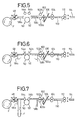
- the film F in the form of a roll is stored in the magazine 44, and the leading end of the film F is gripped by the first pair of feed rollers 48 (see FIG. 5).
- the nip rollers 54a, 54b are moved away from the feed drum 52, and the driven roller 102b of the second feed roller pair is moved away from the drive roller 102a thereof.
- the stepping motor 68 is energized to rotate in one direction, causing the worm 70 and the worm gear 72 to rotate the shaft 74 in the direction indicated by the arrow X.
- the spur gears 76 mounted on the shaft 74 are rotated to elevate the racks 78 and hence the brackets 62, 64.
- the nip rollers 54a, 54b placed on the shoulders 80a, 80b of the brackets 62, 64 are lifted away from the feed drum 52, and the presser guide members 56a, 56b are also spaced away from the feed drum 52 by the plates 86a, 86b which are fixed to the brackets 62, 64.
- the upstream swing plate 92a is angularly moved upwardly about the shaft 94a under the tension of the springs 96 until the upstream guide plate 58a is held in a substantially horizontal attitude, and the downstream swing plate 92b is caused by the links 98 to swing upwardly about the shaft 94b until the downstream guide plate 58b is held in a substantially horizontal attitude (see FIG. 3).
- the ascending movement of the bracket 62 turns the swing guide plate 105 upwardly about the shaft 103, so that the driven roller 102b supported on the swing guide plate 105 is spaced upwardly from the drive roller 102a.
- the leading end of the film F passes between the second pair of feed rollers 102 into a certain position whereupon, as shown in FIG. 6, the driven roller 102b is displaced toward the drive roller 102a and the nip rollers 54a, 54b move toward the feed drum 52.
- the stepping motor 68 is energized to rotate in the opposite direction, rotating the shaft 74 in the direction indicated by the arrow Y.
- the brackets 62, 64 are lowered, and the nip rollers 54a, 54b are moved toward the feed drum 52, gripping the film F.
- the presser guide members 56a, 56b descend to press the film F against the outer circumferential surface of the feed drum 52.
- the upstream and downstream swing plates 92a, 92b are angularly moved downwardly about the respective shafts 94a, 94b, displacing the upstream and downstream guide plates 58a, 58b downwardly out of a position interfering with the respective presser guide members 56a, 56b, as shown in FIG. 4.
- looped paths are defined upstream and downstream, respectively, of the feed drum 52.
- the swing guide plate 105 is angularly moved downwardly, and hence the driven roller 102b is moved downwardly into coaction with the drive roller 102a for thereby gripping the film F therebetween.
- the synchronizing light source 36 When the synchronizing light source 36 is energized, it emits a synchronizing light beam L 2 .
- the synchronizing light beam L 2 is reflected and deflected in a main scanning direction by the resonant light deflector 28, and then is caused by the f ⁇ lens 30 and the reflecting mirrors 32, 40 to scan the reference grating 38.
- the synchronizing light beam L 2 passes through the slits of the reference grating 38, and is applied as a pulsed light signal to the photosensor 42.
- the photosensor 42 then generates a synchronizing signal which is applied to energize the recording light source 26.
- the recording light source 26 generates a recording light beam L 1 , which after being modulated by an image to be recorded, is reflected and deflected in the main scanning direction by the resonant light deflector 28.
- the recording light beam L 1 passes through the f ⁇ lens 30 and is reflected by the reflecting mirrors 32, 34 to scan the film F which is being fed in the auxiliary scanning direction A. Therefore, an image is two-dimensionally recorded on the film F based on the image information carried by the recording light beam L 1 .
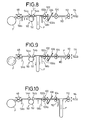
- the recorded length of film F is accommodated as a loop between the second pair of feed rollers 102 and the feed drum 52, as shown in FIG. 8.
- the first pair of feed rollers 48, the feed drum 52, the second pair of feed rollers 102, the third pair of feed rollers 104, and the fourth pair of feed rollers 112 are rotated to feed the film F until its leading end reaches a certain position near the shutter 114, as shown in FIG. 9.
- the movable guide plate 110 is lowered, and the second pair of feed rollers 102 and the third pair of feed rollers 104 are rotated to accommodate the recorded length of film F, which has been accommodated between the second pair of feed rollers 102 and the feed drum 52, as a loop between the third pair of feed rollers 104 and the fourth pair of feed rollers 112.
- the cutter 106 is actuated to cut off the film F to a predetermined length (see FIG. 11), and the shutter 114 is opened to allow the recorded length of film F to be fed toward the image recording apparatus by the fourth pair of feed rollers 112, as shown in FIG. 12.
- the nip rollers 54a, 54b and the driven roller 102b are elevated, the presser guide members 56a, 56b are elevated, and the upstream and downstream guide plates 58a, 58b are turned to a substantially horizontal attitude, by ascending movement of the brackets 62, 64 (see FIG. 3).
- the first pair of feed rollers 48 is reversed to return the unrecorded film F toward the magazine 44, and the third pair of feed rollers 104 and the fourth pair of feed rollers 112 are rotated to introduce the recorded length of film F into the image recording apparatus, as shown in FIG. 13.
- the shutter 114 is then closed.
- the parts of the feed apparatus 50 are now in the condition shown in FIG. 5 in readiness for a next recording process.
- the film F when the recording light beam L 1 is applied to the film F, the film F is gripped between the feed drum 52 and the nip rollers 54a, 54b, and held against the outer circumferential surface of the feed drum 52 by the presser guide members 56a, 56b that are positioned outwards of the nip rollers 54a, 54b. Therefore, the film F is tautly wound around the outer circumferential surface of the feed drum 52 over a certain angular interval without being possibly floated or curved off the outer circumferential surface of the feed drum 52. Consequently, lines recorded on the film F are prevented from being unduly curved or otherwise distorted.
- the upstream and downstream guide plates 58a, 58b are swung downwardly thereby to define looped feed paths. Consequently, the presser guide members 56a, 56b and the upstream and downstream guide plates 58a, 58b are prevented from interfering with each other, avoiding the application of any undue external forces to the film F. Images can thus be recorded smoothly and highly accurately on the film F.
- nip rollers 54a, 54b can be moved toward and away from the feed drum 52, the presser guide members 56a, 56b can be moved toward and away from the feed drum 52, the upstream and downstream guide members 58a ,58b can be angularly moved, and the driven roller 102b can be moved toward and away from the drive roller 102a, all in mechanical unison with each other in response to vertical movement of the brackets 62, 64 of the moving mechanism 60.
- the overall mechanical arrangement for carrying out such movements is much simpler than would be if they were moved under electrical control, and makes it possible to record images highly accurately and efficiently on the film F.
- presser guide members 56a, 56b are shown as being of an arcuately curved shape in the illustrated embodiment, they may be replaced with guide rollers.
- the feed apparatus 50 has been described with respect to a color platemaking process for producing four color-separated films. However, the principles of the present invention are also applicable to a process of recording an image on a single film for black-and-white platemaking, or a process of recording images of four colors on a single film for color platemaking and dividing the film into four plates.
- the feed apparatus 50 may be incorporated in a reading apparatus in which a light beam is applied to a film with image information recorded thereon to photoelectrically read the recorded image information from the film.
Landscapes
- Engineering & Computer Science (AREA)
- Multimedia (AREA)
- Signal Processing (AREA)
- Facsimile Scanning Arrangements (AREA)
- Photographic Developing Apparatuses (AREA)
- Advancing Webs (AREA)
- Handling Of Cut Paper (AREA)
- Paper Feeding For Electrophotography (AREA)
- Delivering By Means Of Belts And Rollers (AREA)
Claims (6)
- Transportvorrichtung zum Transportieren eines abgetasteten Mediums (F) in einer Hilfsabtastrichtung, wobei ein Lichtstrahl (L1) abgelenkt und in einer Hauptabtastrichtung im wesentlichen senkrecht zu der Hilfsabtastrichtung auf das abgetastete Medium (F) gerichtet wird, die umfaßt:eine Transporttrommel (52), die gedreht werden kann, um das abgetastete Medium (F) in der Hilfsabtastrichtung zu transportieren;ein Paar Klemmwalzen (54a, 54b), die in der Hilfsabtastrichtung stromauf bzw. stromab von der Transporttrommel (52) angeordnet sind, um das abgetastete Medium (F) an einer Außenumfangsfläche der Transporttrommel (52) zu halten;einen Bewegungsmechanismus (60), mit dem die Klemmwalzen (54a, 54b) auf die Transporttrommel (52) zu und von ihr weg bewegt werden; gekennzeichnet durch:ein Paar Preß-Leitelemente (56a, 56b), die in der Hilfsabtastrichtung stromauf bzw. stromab von der Transporttrommel (52) angeordnet sind und die das abgetastete Medium (F) jeweils an einer Position, die weiter von einer Position entfernt ist, an der der Lichtstrahl (L1) auf das abgetastete Medium (F) gerichtet wird, als eine Position, an der die Klemmwalzen (54a, 54b) an die Transporttrommel (52) gehalten werden, an die Außenumfangsfläche der Transporttrommel (52) pressen;ein Paar Leitplatten (58a, 58b), die in der Hilfsabtastrichtung stromauf bzw. stromab von der Transporttrommel (52) angeordnet sind, um das abgetastete Medium (F) zu leiten; wobeider Bewegungsmechanismus (60) eine erste Verschiebungseinrichtung (85) umfaßt, die die Preß-Leitelemente (56a, 56b) synchron zur Bewegung der Klemmwalzen (54a, 54b) auf die Transporttrommel (52) zu und von ihr weg auf die Transporttrommel (52) zu und von ihr weg bewegt; undeine zweite Verschiebungseinrichtung (90), die die Leitplatten (58a, 58b) synchron zur Bewegung der Klemmwalzen (54a, 54b) auf die Transporttrommel (52) zu und von ihr weg aus Positionen bewegt, in denen sie den Preß-Leitelementen (56a, 56b) im Weg sind.
- Transportvorrichtung nach Anspruch 1, dadurch gekennzeichnet, daß der Bewegungsmechanismus (60) ein Paar Halterungen (62, 64), die an der Transporttrommel (52) voneinander beabstandet und parallel zueinander angeordnet sind, wobei jede der Klemmwalzen (54a, 54b) drehbar zwischen den Halterungen (62, 64) gelagert ist, und eine Betätigungseinrichtung (66) umfaßt, mit der die Halterungen (62, 64) synchron zueinander vertikal bewegt werden, wobei die erste Verschiebungseinrichtung (85) ein Paar Platten (86a, 86b) umfaßt, die jeweils integral mit den Halterungen (62, 64) ausgebildet sind, und sich die Preß-Leitelemente (56a, 56b) jeweils von den Platten (86a, 86b) aus erstrecken.
- Transportvorrichtung nach Anspruch 1, dadurch gekennzeichnet, daß der Bewegungsmechanismus (60) ein Paar Halterungen (62, 64), die an der Transporttrommel (52) voneinander beabstandet und parallel zueinander angeordnet sind, wobei jede der Klemmwalzen (54a, 54b) drehbar zwischen den Halterungen (63, 64) gelagert ist, und eine Betätigungseinrichtung (66) umfaßt, mit der die Halterungen (62, 64) synchron zueinander vertikal bewegt werden, wobei die zweite Verschiebungseinrichtung (90) ein Paar Schwenkplatten (92a, 92b) umfaßt, die in der Hilfsabtastrichtung stromauf bzw. stromab von der Transporttrommel (52) angeordnet sind, wobei jede von ihnen schwenkbar in Kontakt mit den Halterungen (62, 64) gehalten wird, um die Leitplatten (58a, 58b) winklig aus den Positionen zu bewegen, in denen sie jeweils den Preß-Leitelementen (56a, 56b) im Weg sind, um so gewölbte Transportwege zu bilden, wenn sich die Klemmwalzen (54a, 54b) auf die Transporttrommel (52) zu bewegen.
- Transportvorrichtung nach Anspruch 2 oder 3, dadurch gekennzeichnet, daß die Halterungen (62, 64) plattenförmig sind und ein gabelförmiges unteres Ende aufweisen, das ein Paar Absätze (80a, 80b) zum Auflegen der Klemmwalzen (54a, 54b) umfaßt.
- Transportvorrichtung nach Anspruch 4, dadurch gekennzeichnet, daß die Absätze (80a, 80b) nach außen abwärts geneigt sind, und die an den entsprechenden Absätzen (80a, 80b) angeordneten Klemmwalzen (54a, 54b) von Außenumfangsflächen vertikal verlängerter Führungsnuten (84a, 84b) getragen werden.
- Transportvorrichtung nach einem der Ansprüche 1 bis 5, dadurch gekennzeichnet, daß die Preß-Leitelemente (56a, 56b) bogenartig gekrümmte Form haben.
Applications Claiming Priority (3)
| Application Number | Priority Date | Filing Date | Title |
|---|---|---|---|
| JP06327494A JP3319542B2 (ja) | 1994-03-31 | 1994-03-31 | 被走査体の搬送装置 |
| JP6327494 | 1994-03-31 | ||
| JP63274/94 | 1994-03-31 |
Publications (3)
| Publication Number | Publication Date |
|---|---|
| EP0675630A2 EP0675630A2 (de) | 1995-10-04 |
| EP0675630A3 EP0675630A3 (de) | 1996-10-30 |
| EP0675630B1 true EP0675630B1 (de) | 2000-05-31 |
Family
ID=13224574
Family Applications (1)
| Application Number | Title | Priority Date | Filing Date |
|---|---|---|---|
| EP95104458A Expired - Lifetime EP0675630B1 (de) | 1994-03-31 | 1995-03-27 | Vorrichtung zum Fördern von abgetastetem Material |
Country Status (4)
| Country | Link |
|---|---|
| US (1) | US5617986A (de) |
| EP (1) | EP0675630B1 (de) |
| JP (1) | JP3319542B2 (de) |
| DE (1) | DE69517238T2 (de) |
Families Citing this family (10)
| Publication number | Priority date | Publication date | Assignee | Title |
|---|---|---|---|---|
| JPH0822130A (ja) * | 1994-07-06 | 1996-01-23 | Fuji Photo Film Co Ltd | 被走査体の搬送装置 |
| JP3524985B2 (ja) * | 1995-05-17 | 2004-05-10 | 富士写真フイルム株式会社 | 被走査体の搬送方法および装置 |
| DE69631401T2 (de) * | 1995-09-11 | 2004-12-09 | Noritsu Koki Co., Ltd. | Verfahren zum Vor- und Rückspulen photoempfindlichen Materials |
| JP2833538B2 (ja) * | 1995-09-25 | 1998-12-09 | ノーリツ鋼機株式会社 | フィルム供給装置 |
| US5713504A (en) * | 1995-11-27 | 1998-02-03 | Fuji Photo Film Co., Ltd. | Transport apparatus for auxiliary scanning |
| TWI252031B (en) * | 2004-05-18 | 2006-03-21 | Avision Inc | Duplex scan method capable of quickly detecting a document size |
| US7087861B2 (en) * | 2005-01-05 | 2006-08-08 | Eastman Kodak Company | Media entrance guide in a thermal processor |
| US20080084591A1 (en) * | 2006-10-05 | 2008-04-10 | Rassatt Bradley B | Imaging apparatus with moveable entrance guide |
| US20110278390A1 (en) * | 2010-05-12 | 2011-11-17 | Armbruster Randy E | Media transport system turnover mechanism |
| US20110278389A1 (en) * | 2010-05-12 | 2011-11-17 | Armbruster Randy E | Media transport system drive module |
Family Cites Families (9)
| Publication number | Priority date | Publication date | Assignee | Title |
|---|---|---|---|---|
| US2051036A (en) * | 1933-01-23 | 1936-08-18 | Kinatome Patents Corp | Film handling apparatus and control therefor |
| US2051787A (en) * | 1934-01-15 | 1936-08-18 | Kinatome Patents Corp | Film handling apparatus |
| GB1198007A (en) * | 1967-06-27 | 1970-07-08 | Matsushita Electric Industrial Co Ltd | Magnetic Recording and Reproducing Apparatus |
| US3669331A (en) * | 1971-03-04 | 1972-06-13 | Walter Renold | Free floating pressure roller means and retracting mechanism for film drive |
| JPS586660A (ja) * | 1981-07-06 | 1983-01-14 | Fuji Photo Film Co Ltd | 画像走査装置 |
| US4833496A (en) * | 1988-05-02 | 1989-05-23 | Eastman Kodak Company | Web guiding apparatus |
| US5103322A (en) * | 1990-05-14 | 1992-04-07 | Polaroid Corporation | Scanner with retractable roller feed |
| JP2889736B2 (ja) * | 1991-05-24 | 1999-05-10 | 富士写真フイルム株式会社 | 写真プリンタのペーパー搬送装置 |
| JP3054495B2 (ja) * | 1992-06-18 | 2000-06-19 | 富士写真フイルム株式会社 | 記録材料搬送方法及びその装置並びに画像記録読取装置 |
-
1994
- 1994-03-31 JP JP06327494A patent/JP3319542B2/ja not_active Expired - Fee Related
-
1995
- 1995-03-24 US US08/410,284 patent/US5617986A/en not_active Expired - Lifetime
- 1995-03-27 EP EP95104458A patent/EP0675630B1/de not_active Expired - Lifetime
- 1995-03-27 DE DE69517238T patent/DE69517238T2/de not_active Expired - Lifetime
Also Published As
| Publication number | Publication date |
|---|---|
| JPH07267441A (ja) | 1995-10-17 |
| US5617986A (en) | 1997-04-08 |
| JP3319542B2 (ja) | 2002-09-03 |
| EP0675630A2 (de) | 1995-10-04 |
| DE69517238D1 (de) | 2000-07-06 |
| DE69517238T2 (de) | 2000-10-12 |
| EP0675630A3 (de) | 1996-10-30 |
Similar Documents
| Publication | Publication Date | Title |
|---|---|---|
| US5754314A (en) | Image input system and method for reading images from an original document | |
| US4914452A (en) | Ink sheet/recording paper cassette | |
| EP0675630B1 (de) | Vorrichtung zum Fördern von abgetastetem Material | |
| US6343787B1 (en) | Sheeting transport apparatus having anti-positional offset mechanism | |
| JPH06347923A (ja) | 画像プリンタ | |
| US5060927A (en) | Sheet feeding device | |
| US4598300A (en) | Image building apparatus | |
| EP0677771B1 (de) | Verfahren und Vorrichtung zur Herstellung eines photographischen Abzuges | |
| US5731888A (en) | Apparatus for performing exposure by scanning with optical beams | |
| EP0691585A2 (de) | Gerät zur Zuführung eines abgetasteten Informationsträgers | |
| EP0743271B1 (de) | Verfahren und Apparat zum Zuführen eines abgetasteten Aufzeichnungsträgers | |
| JPH09205580A (ja) | フィルム帯に含まれる画像を走査するためのシステム及びそれを用いた方法 | |
| JPS6083933A (ja) | 画像形成装置 | |
| JP3634910B2 (ja) | 画像記録装置 | |
| US4860060A (en) | Microfiche printing system and method | |
| JPH06183088A (ja) | 記録装置 | |
| EP0723184B1 (de) | Verfahren und Vorrichtung zum Abdrucken von Filme | |
| JP3769061B2 (ja) | 副走査搬送装置 | |
| JP2511513B2 (ja) | 写真合成焼付装置 | |
| JP2579536B2 (ja) | 感材ガイド機構 | |
| US6606170B1 (en) | Apparatus for the manufacture of a photographic print | |
| JP2576800Y2 (ja) | 画像記録装置 | |
| JPH02110060A (ja) | ロール状巻装体の位置ずれ補正機構およびその方法 | |
| JP3628456B2 (ja) | 画像記録装置 | |
| US20020167648A1 (en) | Device for producing microfiche and method for producing a microfiche with such device |
Legal Events
| Date | Code | Title | Description |
|---|---|---|---|
| PUAI | Public reference made under article 153(3) epc to a published international application that has entered the european phase |
Free format text: ORIGINAL CODE: 0009012 |
|
| AK | Designated contracting states |
Kind code of ref document: A2 Designated state(s): DE FR GB |
|
| PUAL | Search report despatched |
Free format text: ORIGINAL CODE: 0009013 |
|
| AK | Designated contracting states |
Kind code of ref document: A3 Designated state(s): DE FR GB |
|
| 17P | Request for examination filed |
Effective date: 19961127 |
|
| 17Q | First examination report despatched |
Effective date: 19981008 |
|
| GRAG | Despatch of communication of intention to grant |
Free format text: ORIGINAL CODE: EPIDOS AGRA |
|
| GRAG | Despatch of communication of intention to grant |
Free format text: ORIGINAL CODE: EPIDOS AGRA |
|
| GRAG | Despatch of communication of intention to grant |
Free format text: ORIGINAL CODE: EPIDOS AGRA |
|
| GRAH | Despatch of communication of intention to grant a patent |
Free format text: ORIGINAL CODE: EPIDOS IGRA |
|
| GRAH | Despatch of communication of intention to grant a patent |
Free format text: ORIGINAL CODE: EPIDOS IGRA |
|
| GRAA | (expected) grant |
Free format text: ORIGINAL CODE: 0009210 |
|
| AK | Designated contracting states |
Kind code of ref document: B1 Designated state(s): DE FR GB |
|
| REF | Corresponds to: |
Ref document number: 69517238 Country of ref document: DE Date of ref document: 20000706 |
|
| ET | Fr: translation filed | ||
| PLBE | No opposition filed within time limit |
Free format text: ORIGINAL CODE: 0009261 |
|
| STAA | Information on the status of an ep patent application or granted ep patent |
Free format text: STATUS: NO OPPOSITION FILED WITHIN TIME LIMIT |
|
| 26N | No opposition filed | ||
| REG | Reference to a national code |
Ref country code: GB Ref legal event code: IF02 |
|
| REG | Reference to a national code |
Ref country code: GB Ref legal event code: 732E |
|
| REG | Reference to a national code |
Ref country code: FR Ref legal event code: TP Ref country code: FR Ref legal event code: CD |
|
| PGFP | Annual fee paid to national office [announced via postgrant information from national office to epo] |
Ref country code: FR Payment date: 20100324 Year of fee payment: 16 |
|
| PGFP | Annual fee paid to national office [announced via postgrant information from national office to epo] |
Ref country code: GB Payment date: 20100322 Year of fee payment: 16 |
|
| PGFP | Annual fee paid to national office [announced via postgrant information from national office to epo] |
Ref country code: DE Payment date: 20100303 Year of fee payment: 16 |
|
| GBPC | Gb: european patent ceased through non-payment of renewal fee |
Effective date: 20110327 |
|
| REG | Reference to a national code |
Ref country code: FR Ref legal event code: ST Effective date: 20111130 |
|
| PG25 | Lapsed in a contracting state [announced via postgrant information from national office to epo] |
Ref country code: DE Free format text: LAPSE BECAUSE OF NON-PAYMENT OF DUE FEES Effective date: 20111001 Ref country code: FR Free format text: LAPSE BECAUSE OF NON-PAYMENT OF DUE FEES Effective date: 20110331 |
|
| REG | Reference to a national code |
Ref country code: DE Ref legal event code: R119 Ref document number: 69517238 Country of ref document: DE Effective date: 20111001 |
|
| PG25 | Lapsed in a contracting state [announced via postgrant information from national office to epo] |
Ref country code: GB Free format text: LAPSE BECAUSE OF NON-PAYMENT OF DUE FEES Effective date: 20110327 |