EP0676234A1 - Dispositif d'agitation de récipient - Google Patents
Dispositif d'agitation de récipient Download PDFInfo
- Publication number
- EP0676234A1 EP0676234A1 EP95302203A EP95302203A EP0676234A1 EP 0676234 A1 EP0676234 A1 EP 0676234A1 EP 95302203 A EP95302203 A EP 95302203A EP 95302203 A EP95302203 A EP 95302203A EP 0676234 A1 EP0676234 A1 EP 0676234A1
- Authority
- EP
- European Patent Office
- Prior art keywords
- magnetic field
- agitating device
- propelled
- field means
- vessel
- Prior art date
- Legal status (The legal status is an assumption and is not a legal conclusion. Google has not performed a legal analysis and makes no representation as to the accuracy of the status listed.)
- Withdrawn
Links
- 238000003760 magnetic stirring Methods 0.000 claims abstract description 32
- 230000033001 locomotion Effects 0.000 claims abstract description 11
- 230000008878 coupling Effects 0.000 claims abstract description 4
- 238000010168 coupling process Methods 0.000 claims abstract description 4
- 238000005859 coupling reaction Methods 0.000 claims abstract description 4
- 239000000463 material Substances 0.000 claims description 17
- CWYNVVGOOAEACU-UHFFFAOYSA-N Fe2+ Chemical compound [Fe+2] CWYNVVGOOAEACU-UHFFFAOYSA-N 0.000 claims description 2
- 238000005096 rolling process Methods 0.000 abstract description 16
- 230000000694 effects Effects 0.000 description 4
- ORQBXQOJMQIAOY-UHFFFAOYSA-N nobelium Chemical compound [No] ORQBXQOJMQIAOY-UHFFFAOYSA-N 0.000 description 3
- 238000013019 agitation Methods 0.000 description 2
- 238000011109 contamination Methods 0.000 description 2
- 239000001963 growth medium Substances 0.000 description 2
- 230000001154 acute effect Effects 0.000 description 1
- XAGFODPZIPBFFR-UHFFFAOYSA-N aluminium Chemical compound [Al] XAGFODPZIPBFFR-UHFFFAOYSA-N 0.000 description 1
- 229910052782 aluminium Inorganic materials 0.000 description 1
- 230000003698 anagen phase Effects 0.000 description 1
- 230000001413 cellular effect Effects 0.000 description 1
- 239000000470 constituent Substances 0.000 description 1
- 238000012258 culturing Methods 0.000 description 1
- 230000009977 dual effect Effects 0.000 description 1
- 239000002360 explosive Substances 0.000 description 1
- 231100001261 hazardous Toxicity 0.000 description 1
- 238000010438 heat treatment Methods 0.000 description 1
- 239000007788 liquid Substances 0.000 description 1
- 238000009630 liquid culture Methods 0.000 description 1
- 238000000034 method Methods 0.000 description 1
- 238000009629 microbiological culture Methods 0.000 description 1
- 244000005700 microbiome Species 0.000 description 1
- 229920003023 plastic Polymers 0.000 description 1
- 239000004033 plastic Substances 0.000 description 1
- 238000002360 preparation method Methods 0.000 description 1
- 239000012857 radioactive material Substances 0.000 description 1
- 230000001105 regulatory effect Effects 0.000 description 1
- 238000003756 stirring Methods 0.000 description 1
Images

Classifications
-
- B—PERFORMING OPERATIONS; TRANSPORTING
- B01—PHYSICAL OR CHEMICAL PROCESSES OR APPARATUS IN GENERAL
- B01F—MIXING, e.g. DISSOLVING, EMULSIFYING OR DISPERSING
- B01F33/00—Other mixers; Mixing plants; Combinations of mixers
- B01F33/45—Magnetic mixers; Mixers with magnetically driven stirrers
Definitions
- the present invention relates to a vessel agitating device for use with a magnetic stirring device. More particularly, but not exclusively the present invention relates to a tube mixer device and a bottle roller device for use with a magnetic stirring device.
- One kind of existing device used to agitate vessels containing materials to be mixed generally comprises a plate arranged at an angle between 45° to 90° to a horizontal plane and adapted to rotate.
- the plate is provided with gripping means to attach the vessels, typically tubes, arranged around the periphery of the plate.
- Such devices are commonly referred to as tube mixers.
- Tubes containing materials to be agitated are placed within the gripping means on the rotating plate and the rotary motion of the angled plate acts upon the material in the tubes thereby mixing the contents.
- Rotation of the angled plate is conventionally effected by an electric motor.
- Another kind of existing device used to agitate vessels containing materials to be mixed generally comprises a plurality of horizontal rollers rotatably mounted in a side by side arrangement. Vessels such as bottles containing materials to be agitated are placed on their sides on the arrangement of horizontal rollers and the rolling motion of the rollers acts upon the material in the bottles thereby mixing the contents. Such devices are commonly referred to as bottle rollers. Movement of the horizontal rollers is conventionally effected by an electric motor.
- Such equipment generally comprises a vessel support table and a propelling magnet mounted on one end of the motor shaft of an electric motor arranged beneath the vessel support table.
- a vessel whose contents are to be mixed is placed upon the vessel support table and a magnetic bar is placed inside the vessel.
- the electric motor is activated, the propelling magnet mounted on the motor shaft rotates and the magnetic bar in the vessel follows the motion of the propelling magnet thereby mixing the contents of the vessel.
- such magnetic stirring devices also include a heating element so that the vessel contents can be heated and/or stirred.
- Such equipment is widely used for example in laboratories to effect efficient mixing of liquid constituents. Often each piece of equipment is dedicated to one particular use or position within the laboratory, in particular, if the equipment is to be used to agitate vessels containing microbial cultures, cellular cultures, radioactive materials or any other material that must be strictly contained to comply with safety regulations for the avoidance of contaminations.
- a laboratory procedure may also require the use of more than one type of the aforementioned equipment. For example, it may be necessary to use a magnetic stirring device for the preparation of a culture medium and then a bottle roller device for culturing microorganisms or cells in the liquid culture medium where continuous agitation during the growth phase is required.
- a vessel agitating device for use with a magnetic stirring device having a propelling magnetic field means characterised in that said vessel agitating device comprises a base element and an outer element said outer element being adapted to receive and retain vessels and being rotatably mounted relative to the base element and having a propelled magnetic field means associated therewith and further characterised in that drive means are provided through which said outer element is driven by said propelled magnetic field means, the arrangement being such that the rotary movement of the outer element is effected by magnetic coupling of the propelled magnetic field means associated with the outer element to a propelling magnetic field means of a magnetic stirring device.
- the outer element comprises a member adapted for releasable attachment of vessels to be agitated said member being rotatably mounted at an angle relative to the base element and wherein the drive means are inclined relative to the axis of rotation of the propelled magnetic field means.
- the outer element comprises a plurality of substantially parallel aligned rollers each being rotatably mounted and spaced apart one from another by an amount sufficient to form a valley therebetween which provides a seating for receiving vessels to be agitated and the rollers being mounted for unidirectional rotation about their longitudinal axes in response to output from the drive means.
- the stirrer By magnetically coupling movement of the propelled magnet associated with the outer element to the movement of the propelling magnet of the magnetic stirrer the stirrer can be converted to perform either a tube mixing or a bottle rolling function.
- a magnetic stirring device can acquire dual functions and thus obviate the need for the provision of separate tube mixing or bottle rolling equipment. This has particular advantages in confined laboratory working conditions.
- the tube mixing or bottle rolling devices can be used as attachments for a magnetic stirring device or as dedicated tube mixing, or bottle rolling devices which could be used within an oven, incubator, flame proof area or any other vessel or tank, where for example, the provision of electrical equipment would be a hazard.
- the drive means comprises a gears system.
- the drive means comprises a belt system.
- Other suitable drive means will be well known to a person skilled in the art but a further example could include a chain and sprocket arrangement.
- the propelled magnetic field means is housed within the base element.
- the propelled magnetic field means is a bar shaped magnet.
- the tube mixing device or bottle rolling device is constructed of substantially non-ferrous materials, for example, aluminum or plastics materials, with the exception of magnetic field means.
- a magnetic stirring device incorporating a tube mixing device.
- a magnetic stirring device incorporating a bottle rolling device.
- the base element of the tube mixing device or bottle rolling device is releasably secured to the magnetic stirring device by fixing means.
- the outer element of the tube mixing device will be a plate but it will be understood that it could comprise a frame member provided it is capable of fulfilling its function.
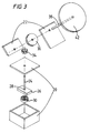
- a magnetic stirring device 10 comprising a rotating magnet element 12 coupled to an electric motor means 14 accommodated within a housing 16.
- the tube mixing device 18 comprises a base element 20 and an outer element 42 arranged at an acute angle relative to each other.
- the base element 20 houses a vertically oriented driving rod 24 which has a permanent bar magnet 26 which is to be propelled fixed adjacent to a lower end 28 thereof.
- the lower end 28 of the driving rod 24 is mounted on ball bearings 30, the arrangment being such that the bar magnet 26 and driving rod 24 can rotate freely on the ball bearings.
- the upper end 32 of the driving rod 24 extends to the exterior of the base element 20 and carries a first gear wheel 34 which is arranged in meshing engagement with a further gear wheel 36.
- the further wheel gear 36 is carried on an inclined second driving rod 38 which is arrangeable at any angle between 0° to 90° to the driving rod 24.
- the upper end 40 of the second driving rod 38 is attached to the outer element a plate 42 which will rotate when the device is driven.
- the plate 42 is provided with gripping means 44 such as spring clips which will hold the tubes containing the materials to be mixed.
- the second driving rod 38 and the plate 42 may be supported by bracket means 22.
- fixing means for securing the tube mixing device 18 to the magnetic stirring device 10.
- Suitable fixing means will be well known to the person skilled in the art but examples could include straps, brackets, screws, adjustable eccentric cams or the like.
- the base structure 20 is positioned and fixed on to the housing 16 of the magnetic stirring device 10.
- the propelling magnetic element 12 carried on the motor shaft rotates.
- the propelled bar magnet 26 attached to the driving rod 24 is magnetically coupled to the propelling magnetic element 12 and thus also rotates.
- Rotation of the propelled bar magnet 26 effects rotation of the vertically orientated driving rod 24 which drives in turn the meshed gear wheels 34 and 36 and the inclined second driving rod 38.
- Rotation of the inclined second driving rod 38 causes the plate 42 to rotate.
- a vessel (not shown) containing materials to be agitated may be fixed in the gripping means 44 of the plate 42. The rotational motion of the plate 42 acts upon the material in the tube to agitate and mix the contents.
- a magnetic stirring device 100 comprising a rotating magnet element 102 coupled to an electric motor means 104 accommodated within a housing 106.
- the bottle rotating device 108 comprises a base element 110 and an outer element 114.
- the outer element 114 comprises a series of rotatably mounted rollers.
- the rollers 114 are mounted in substantially parallel alignment and each roller is spaced apart from the adjacent roller by an amount sufficient to form a valley therebetween which provides a seating for receiving the vessel to be agitated.
- the rollers will all rotate in the same direction and may all be driven by the drive means. In an alternative arrangement some of the rollers may be driven and some of the rollers may be passive.
- the base element 110 houses a vertically oriented driving rod 116 which has a permanent bar magnet 118 which is to be propelled fixed adjacent a lower end 120 thereof.
- the lower end 120 of the driving rod 116 is mounted on ball bearings 124, the arrangement being such that the bar magnet 118 and the driving rod 116 can rotate freely on the ball bearings.
- the upper end 126 of the driving rod 116 extends to the exterior the base element 110 and carries a first gear wheel 128 which is arranged in meshing engagement with a further system of connecting gear wheels 130.
- the final gear wheel 132 of the system of interconnecting gear wheels 130 is arranged in meshing engagement with a drive wheel 134 of the horizontal arrangement of rollers 114.
- the system of interconnecting gears and the roller assembly are accommodated within a housing 136 mounted on top of the base at 110.
- fixing means securing the bottle rolling device 108 to the magnetic stirring device 100.
- Suitable fixing means will be well known to a person skilled in the art but examples could include the straps, brackets, screws, adjustable eccentric cams or the like.
- the base structure 110 is positioned and fixed on to the housing 106 of the magnetic stirring device 100.
- the electric motor means 104 of the magnetic stirring device 100 When the electric motor means 104 of the magnetic stirring device 100 is activated, the propelling magnetic element 102 carried on the motor shaft rotates.
- the propelled bar magnet 118 attached to the driving rod 116 is magnetically coupled to the propelling magnet element 102.
- Rotation of the propelled bar magnet 118 effects rotation of the vertically oriented driving rod 122 which drives in turn the first gear wheel 128, the system of interconnecting wheels 130, the final gear wheel 132 and the drive wheel 134.
- Rotation of the drive wheel 134 causes the arrangement of horizontal rollers 114 to rotate in one direction relative to the base structure.
- a vessel (not shown) containing material to be agitated may be placed on its side in the valley between adjacent rollers 114.
- the rotational motion of the rollers 114 acts upon the material within the vessel thereby agitating and mixing the contents.
Landscapes
- Chemical & Material Sciences (AREA)
- Chemical Kinetics & Catalysis (AREA)
- Mixers With Rotating Receptacles And Mixers With Vibration Mechanisms (AREA)
- Mixers Of The Rotary Stirring Type (AREA)
Applications Claiming Priority (2)
| Application Number | Priority Date | Filing Date | Title |
|---|---|---|---|
| GB9406852 | 1994-04-07 | ||
| GB9406852A GB9406852D0 (en) | 1994-04-07 | 1994-04-07 | Mixer and rotator attachments |
Publications (1)
| Publication Number | Publication Date |
|---|---|
| EP0676234A1 true EP0676234A1 (fr) | 1995-10-11 |
Family
ID=10753126
Family Applications (1)
| Application Number | Title | Priority Date | Filing Date |
|---|---|---|---|
| EP95302203A Withdrawn EP0676234A1 (fr) | 1994-04-07 | 1995-03-31 | Dispositif d'agitation de récipient |
Country Status (3)
| Country | Link |
|---|---|
| EP (1) | EP0676234A1 (fr) |
| CA (1) | CA2146500A1 (fr) |
| GB (1) | GB9406852D0 (fr) |
Cited By (4)
| Publication number | Priority date | Publication date | Assignee | Title |
|---|---|---|---|---|
| WO2010100212A1 (fr) | 2009-03-05 | 2010-09-10 | RATIONAL Technische Lösungen GmbH | Mélangeur multifonction pour des applications de laboratoire |
| CN109833814A (zh) * | 2019-04-09 | 2019-06-04 | 菲舍尔航空部件(镇江)有限公司 | 一种卧式磁力混胶装置 |
| CN112827406A (zh) * | 2021-01-11 | 2021-05-25 | 江苏德莱利建筑装饰工程有限公司 | 一种水性环氧地坪漆的搅拌装置 |
| WO2022248158A1 (fr) * | 2021-05-27 | 2022-12-01 | Ika - Werke Gmbh & Co. Kg | Adaptateur de fonction pour agitateur magnétique et ensemble agitateur magnétique comprenant un agitateur magnétique et un adaptateur de fonction |
Families Citing this family (2)
| Publication number | Priority date | Publication date | Assignee | Title |
|---|---|---|---|---|
| CN107177488A (zh) * | 2017-06-26 | 2017-09-19 | 广州瑞能医学科技有限公司 | 一种液体混合装置 |
| WO2023108295A1 (fr) * | 2021-12-16 | 2023-06-22 | Stemcell Technologies Canada Inc. | Appareil de support de récipient et procédés d'utilisation |
Citations (2)
| Publication number | Priority date | Publication date | Assignee | Title |
|---|---|---|---|---|
| FR2514510A1 (fr) * | 1981-10-08 | 1983-04-15 | Mochida Pharm Co Ltd | Appareil pour faire tourner des recipients de reaction dans une attitude inclinee |
| US5299864A (en) * | 1992-03-25 | 1994-04-05 | Stovall Life Science, Inc. | Laboratory container rolling device |
-
1994
- 1994-04-07 GB GB9406852A patent/GB9406852D0/en active Pending
-
1995
- 1995-03-31 EP EP95302203A patent/EP0676234A1/fr not_active Withdrawn
- 1995-04-06 CA CA002146500A patent/CA2146500A1/fr not_active Abandoned
Patent Citations (2)
| Publication number | Priority date | Publication date | Assignee | Title |
|---|---|---|---|---|
| FR2514510A1 (fr) * | 1981-10-08 | 1983-04-15 | Mochida Pharm Co Ltd | Appareil pour faire tourner des recipients de reaction dans une attitude inclinee |
| US5299864A (en) * | 1992-03-25 | 1994-04-05 | Stovall Life Science, Inc. | Laboratory container rolling device |
Cited By (5)
| Publication number | Priority date | Publication date | Assignee | Title |
|---|---|---|---|---|
| WO2010100212A1 (fr) | 2009-03-05 | 2010-09-10 | RATIONAL Technische Lösungen GmbH | Mélangeur multifonction pour des applications de laboratoire |
| DE102009011987A1 (de) * | 2009-03-05 | 2010-09-16 | RATIONAL Technische Lösungen GmbH | Mischgerät für den Laborbetrieb |
| CN109833814A (zh) * | 2019-04-09 | 2019-06-04 | 菲舍尔航空部件(镇江)有限公司 | 一种卧式磁力混胶装置 |
| CN112827406A (zh) * | 2021-01-11 | 2021-05-25 | 江苏德莱利建筑装饰工程有限公司 | 一种水性环氧地坪漆的搅拌装置 |
| WO2022248158A1 (fr) * | 2021-05-27 | 2022-12-01 | Ika - Werke Gmbh & Co. Kg | Adaptateur de fonction pour agitateur magnétique et ensemble agitateur magnétique comprenant un agitateur magnétique et un adaptateur de fonction |
Also Published As
| Publication number | Publication date |
|---|---|
| CA2146500A1 (fr) | 1995-10-08 |
| GB9406852D0 (en) | 1994-06-01 |
Similar Documents
| Publication | Publication Date | Title |
|---|---|---|
| CA2147586C (fr) | Dispositif a secousses a mouvement orbital | |
| EP0676234A1 (fr) | Dispositif d'agitation de récipient | |
| AU626039B2 (en) | Apparatus for mixing viscous materials | |
| CN202289943U (zh) | 磁力搅拌装置 | |
| CN210964876U (zh) | 一种双向搅拌装置 | |
| CN114890522B (zh) | 一种海洋废水混合封装排放装置 | |
| JP2002361059A (ja) | 攪拌装置及び攪拌用容器 | |
| CN208372944U (zh) | 一种节能型搅拌机 | |
| JP3061352B2 (ja) | 軌道振盪装置 | |
| GB2288745A (en) | Orbital shaking device magnetically coupled to a magnetic stirring device | |
| JPH08290049A (ja) | 攪拌装置 | |
| CN218924486U (zh) | 一种混合搅拌装置 | |
| CN216910011U (zh) | 一种水处理药剂混合搅拌装置 | |
| CN218047569U (zh) | 一种药学试剂搅拌装置 | |
| CN216799617U (zh) | 一种磁力搅拌器 | |
| CN212068617U (zh) | 一种双行星搅拌机 | |
| CN210495992U (zh) | 一种改性材料均化卧式混合机 | |
| CN217746667U (zh) | 一种饮料混合装置 | |
| CN222724336U (zh) | 一种匀速化学工程浆料反应釜 | |
| CN218539406U (zh) | 一种废水处理用电氧化装置 | |
| CN218579935U (zh) | 一种中草药制剂发酵用搅拌装置 | |
| CN213434143U (zh) | 一种高效的三维运动混合机 | |
| CN212188762U (zh) | 一种液态空气净化负氧离子涂料的加工装置 | |
| CN223948186U (zh) | 一种建筑施工用混料装置 | |
| CN212701747U (zh) | 一种用于工业的全自动搅拌机 |
Legal Events
| Date | Code | Title | Description |
|---|---|---|---|
| PUAI | Public reference made under article 153(3) epc to a published international application that has entered the european phase |
Free format text: ORIGINAL CODE: 0009012 |
|
| AK | Designated contracting states |
Kind code of ref document: A1 Designated state(s): DE FR GB |
|
| STAA | Information on the status of an ep patent application or granted ep patent |
Free format text: STATUS: THE APPLICATION IS DEEMED TO BE WITHDRAWN |
|
| 18D | Application deemed to be withdrawn |
Effective date: 19960312 |