EP0676242A2 - Verfahren und Vorrichtung zum elektrostatischen Sprühbeschichten - Google Patents
Verfahren und Vorrichtung zum elektrostatischen Sprühbeschichten Download PDFInfo
- Publication number
- EP0676242A2 EP0676242A2 EP95410023A EP95410023A EP0676242A2 EP 0676242 A2 EP0676242 A2 EP 0676242A2 EP 95410023 A EP95410023 A EP 95410023A EP 95410023 A EP95410023 A EP 95410023A EP 0676242 A2 EP0676242 A2 EP 0676242A2
- Authority
- EP
- European Patent Office
- Prior art keywords
- coating
- trigger
- voltage
- electrode
- value
- Prior art date
- Legal status (The legal status is an assumption and is not a legal conclusion. Google has not performed a legal analysis and makes no representation as to the accuracy of the status listed.)
- Withdrawn
Links
Images


Classifications
-
- B—PERFORMING OPERATIONS; TRANSPORTING
- B05—SPRAYING OR ATOMISING IN GENERAL; APPLYING FLUENT MATERIALS TO SURFACES, IN GENERAL
- B05B—SPRAYING APPARATUS; ATOMISING APPARATUS; NOZZLES
- B05B12/00—Arrangements for controlling delivery; Arrangements for controlling the spray area
-
- B—PERFORMING OPERATIONS; TRANSPORTING
- B05—SPRAYING OR ATOMISING IN GENERAL; APPLYING FLUENT MATERIALS TO SURFACES, IN GENERAL
- B05B—SPRAYING APPARATUS; ATOMISING APPARATUS; NOZZLES
- B05B5/00—Electrostatic spraying apparatus; Spraying apparatus with means for charging the spray electrically; Apparatus for spraying liquids or other fluent materials by other electric means
- B05B5/025—Discharge apparatus, e.g. electrostatic spray guns
- B05B5/053—Arrangements for supplying power, e.g. charging power
- B05B5/0531—Power generators
Definitions
- the invention relates to a method and a device for electrostatic spraying of liquid or pulverulent coating product and more particularly relates to an improvement of the electrostatic charging means of the coating product making it possible to obtain a coating of optimum and constant thickness whatever the shape of the object to be coated.
- the invention also makes it possible to improve the deposition yield compared to what is obtained with conventional devices, thereby saving coating material.
- the coating product is electrostatically charged by one or more electrodes in order to follow the lines of electrostatic field between the projection device and the object to be coated.
- Charging can be carried out by contact of the product with the electrode or by Corona discharge from the electrode.
- the intensity of the electric force undergone by each particle of coating product depends on the charge carried by the particle and on the ambient electrostatic field.
- the latter is a function, among other things, of the geometric configuration of the object to be coated. Indeed, if a sharp edge of the object is placed opposite the projection device, the field lines tend to all close on this edge. The particles being guided by the electrostatic field, this leads to an accumulation of product at this location while the flat surfaces in the vicinity of the edge are insufficiently coated.
- the electrostatic field lines tend to close on the edges of the cavity, which tends to prevent the coating product from entering the bottom of the cavity in question.
- the invention solves all of these problems.
- It relates to a method for electrostatic projection of a coating product, characterized in that the value of the supply voltage of at least one electrostatic charging electrode is controlled during the coating of an object as a function of the geometric configuration of said object. .
- the process of the invention it is possible to reduce both the charge of each particle and the intensity of the electrostatic field between the device and the object to be coated at will, and in particular when coating sharp edges or cavities.
- This makes it possible to reduce the intensity of the electric force undergone by each particle of product and makes it possible to use more efficiently the aerodynamic forces created by the driving air.
- it is then possible to precisely direct the jet of coating product sprayed mainly with the entrainment air.
- the invention also relates to a device for electrostatic projection of a coating product comprising at least one charging electrode, characterized in that it comprises means for controlling the value of the supply voltage of said electrode as a function of the geometric configuration of the object to be coated.
- the invention finally relates to a manual device for electrostatic projection of coating product comprising at least one charging electrode and provided with an actuating trigger connected to means for supplying coating product, characterized in that it comprises a means for adjusting the supply voltage of said electrode sensitive to the position of said trigger.
- the powder spray gun 1 shown in Figure 1 is, except for the high voltage control system, built according to the rules of the art. It comprises a barrel 2 and a handle 3 intended to be taken in hand by an operator. It is supplied with air-powder mixture through a conduit 4 in which is housed an electric cable 5 supplying the high voltage unit 6 embedded in the barrel 2. The high voltage unit 6 is electrically connected to an electrode load 7 housed in the spray nozzle 8 located at the end of the duct 4.
- a trigger 10 intended to be actuated by the operator.
- This trigger carries a first extension 11 capable of controlling a first switch 12 connected to the cable 5.
- the position of the switch is detected in the general control system of the device and the pneumatic powder drive system and the supply in high unit voltage 6 are controlled from this information. The position of the trigger therefore makes it possible to activate or not the projector.
- the trigger has a second extension 13 capable of controlling a second switch 14.
- the closing of the switches 12 and 14 takes place in positions different from the trigger 10.
- the switch 12 is activated for a low movement of the trigger while the switches 12 and 14 are activated for maximum movement of the trigger.
- Two springs 15 and 16 respectively ensure the deactivation of the switches 12 and 14.
- the stiffness constants of the springs 15 and 16 may possibly be different, for example the stiffness constant of the spring 16 may be greater than that of the spring 15.
- the spring 15 is constituted by the electrical contact blade of the switch 12.
- the switch 12 is controlled for a low pressure of the operator's finger while the switch 14 is controlled for a higher pressure operator's finger.
- the switches 11 and 13 are mounted on the supply line of the high voltage unit, they can be connected to a step-up transformer 9.
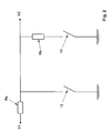
- FIG. 2 On the block diagram of Figure 2, there is shown a DC voltage arrival V1 and the voltage V2 which is delivered to the primary of the transformer 9.
- a voltage divider bridge is made by two resistors Ra and Rb. At rest, the switches 12 and 14 are closed, V2 is therefore zero. The power dissipated in the resistance Ra is low and does not risk damaging the equipment.
- the voltage V2 becomes equal to V1 minus the voltage across the resistance Ra. This corresponds to 100% of the value of the voltage which can be supplied to the transformer 9.
- the switch 14 When the switch 14 is not activated, that is to say when it is closed, the voltage V2 drops because the bridge voltage divider is activated: Part of the electric current is dissipated in the resistor Rb.
- Ra and Rb such that the ratio Rb / (Ra + Rb) is equal to the desired ratio between the voltages desired at the electrode, for example 60%.
- the value of the maximum voltage is set by the operator at a projector control panel, not shown, which controls the voltage source to which the cable 5 is connected and which delivers the voltage V1.
- FIG. 3a represents the position of the trigger at rest, that is to say without operator pressure: no product is supplied to the gun 1 and no high voltage is delivered by the unit 6.
- FIG. 3b represents the position of the trigger when the switch 12 is open and the switch 14 is closed: the air-powder mixture is supplied to the gun by the conduit 4 and the high voltage at the electrode 7 is equal to one determined fraction, for example 60%, of the value that is set by the operator at the general gun control console.
- Figure 3c shows the position of the trigger when switch 12 and switch 14 are open: the air-powder mixture is supplied to the gun via line 4 and the high voltage at electrode 7 is equal to 100% of that set by the operator at the general gun control console.
- the operator When the operator coats parts having large flat surfaces, he exerts strong pressure on the trigger 10 in order to move the latter of its maximum stroke. In this case, the two switches 12 and 14 are activated, the position of the trigger is that shown in FIG. 3c and the voltage at the electrode is maximum.
- the coating product is fully charged and completely undergoes the electrostatic effect. The deposition yield is satisfactory due to the use of the electrostatic effect.
- the coating product is uniformly distributed over the surface to be coated.
- the coating product consumed by the device is permanently deposited so optimal on the object, namely without accumulation on the edges but up to the bottom of the cavities, which avoids overconsumption of product.
- the known advantages of coating by the electrostatic route in particular in terms of the deposition yield, are preserved.
- the trigger 10 has been shown as capable of allowing the supply of the electrode 7 with two values, but the number of values is not limited to two. It suffices to provide a number of switches equivalent to the switches 12 and 14 and to house them in the projector opposite appropriate extensions of the trigger. In the case of three supply values for electrode 7, it will be advantageous to provide a lower voltage for electrode 7 for coating the cavities than for coating the edges.
- the actuation trigger may be progressive operation, that is to say continuous over an operating range.
- the extension 13 of the trigger is mechanically connected to the cursor 50 of a variable potentiometer 51.
- the other elements identical to those of FIG. 2 have the same references, the operation is similar.
- the potential V2 depends on the position of the cursor 50 on the potentiometer 51 because the ratio Rb / (Ra + Rb) previously mentioned depends of the active fraction of potentiometer 51. All the values included in a defined operating range can then be chosen by the operator, which will be useful in the case of particularly complex parts. In the latter case, it is possible to arrange all the members for selecting the value of the high voltage applied to the electrode 7 on the gun 1, possibly including a display: it is no longer necessary to provide a console separate order.
- the invention also applies to the case of a sprayer of liquid coating product.
- the same multi-level or progressive operation trigger structures as described above can be used.
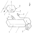
- FIG. 5 The installation of Figure 5 is, except for the high voltage control system, built according to the rules of the art. It comprises an automatic coating machine 101 carrying a projector 102 of liquid paint, for example rotary, housed at the end of an arm 103 movable vertically.
- the spray bowl 104 can be brought to high voltage by any known means and thus constitutes a charging electrode.
- a sensor, for example an optical sensor, 110 detects the shape of objects 111, such as for example bodies of a washing machine, transported by a conveyor opposite the projector 102.
- the objects 111 may have planar surfaces 111a, edges 111b and cavities 111c.
- the sensor 110 is connected to a control unit 112, which controls the machine 101 and a high voltage generator 113, in particular as a function of the signal received from the sensor 110.
- the unit 112 is provided with a memory in which the geometric configurations of the objects likely to be treated in the installation.
- the unit 112 recognizes the objects and adapts the coating parameters, such as the positioning of the arm 103, the flow of paint supplied to the projector 103 and the value of the high voltage delivered by the generator. 113, accordingly.
- the value of the high voltage varies during the coating of the body 111. Thus, it is maximum when coating a flat surface 111a and it is reduced to a fraction of the maximum voltage when coating an edge 111b or to inside a cavity 111c. The accumulation of paint on the edge 111b is thus avoided, while it is possible to properly coat the interior of the hollow body 111.
Landscapes
- Application Of Or Painting With Fluid Materials (AREA)
- Electrostatic Spraying Apparatus (AREA)
Applications Claiming Priority (2)
| Application Number | Priority Date | Filing Date | Title |
|---|---|---|---|
| US22067694A | 1994-03-31 | 1994-03-31 | |
| US220676 | 1994-03-31 |
Publications (2)
| Publication Number | Publication Date |
|---|---|
| EP0676242A2 true EP0676242A2 (de) | 1995-10-11 |
| EP0676242A3 EP0676242A3 (de) | 1996-06-05 |
Family
ID=22824506
Family Applications (1)
| Application Number | Title | Priority Date | Filing Date |
|---|---|---|---|
| EP95410023A Withdrawn EP0676242A3 (de) | 1994-03-31 | 1995-03-30 | Verfahren und Vorrichtung zum elektrostatischen Sprühbeschichten. |
Country Status (2)
| Country | Link |
|---|---|
| US (1) | US5503880A (de) |
| EP (1) | EP0676242A3 (de) |
Cited By (1)
| Publication number | Priority date | Publication date | Assignee | Title |
|---|---|---|---|---|
| WO2014172203A1 (en) * | 2013-04-17 | 2014-10-23 | Finishing Brands Holdings Inc. | Electrostatic spray tool system |
Families Citing this family (14)
| Publication number | Priority date | Publication date | Assignee | Title |
|---|---|---|---|---|
| JP3354038B2 (ja) * | 1995-09-29 | 2002-12-09 | 本田技研工業株式会社 | 静電塗装方法 |
| US5678770A (en) * | 1996-01-03 | 1997-10-21 | Shah; Amal B. | Powder coating spray gun with resettable voltage multiplier |
| US5817373A (en) * | 1996-12-12 | 1998-10-06 | Micron Display Technology, Inc. | Dry dispense of particles for microstructure fabrication |
| US6780491B1 (en) | 1996-12-12 | 2004-08-24 | Micron Technology, Inc. | Microstructures including hydrophilic particles |
| DE19838275A1 (de) * | 1998-08-22 | 2000-02-24 | Itw Gema Ag | Manuelle Sprühbeschichtungspistole |
| US6460787B1 (en) * | 1998-10-22 | 2002-10-08 | Nordson Corporation | Modular fluid spray gun |
| USD441833S1 (en) | 1998-11-26 | 2001-05-08 | Itw Gema Ag | Spray coating device |
| US6758423B1 (en) * | 1999-09-17 | 2004-07-06 | Nordson Corporation | Spray gun with data device and method of control |
| USD447791S1 (en) | 2000-12-14 | 2001-09-11 | The Easthill Group, Inc. | Spray gun |
| GB2377191B (en) * | 2001-07-06 | 2003-09-10 | Reckitt Benckiser | Spraying device |
| US6676049B2 (en) | 2001-11-16 | 2004-01-13 | Efc Systems, Inc. | Bell cup powder spray applicator |
| WO2005018825A1 (en) * | 2003-08-18 | 2005-03-03 | Nordson Corporation | Wireless operator interface for material application system |
| BR112012023070A2 (pt) * | 2010-03-18 | 2019-09-24 | Axia Acquisition Corp | ajuste de fluxo de bomba em ferramenta. |
| CA140534S (en) * | 2010-12-30 | 2012-12-03 | Illinois Tool Works | Powder spray gun |
Family Cites Families (11)
| Publication number | Priority date | Publication date | Assignee | Title |
|---|---|---|---|---|
| FR1360743A (fr) * | 1963-02-19 | 1964-05-15 | Sames Mach Electrostat | Perfectionnements aux pistolets pour pulvérisation et projection électrostatique de peinture |
| CH505653A (de) * | 1968-04-26 | 1971-04-15 | Mueller Ernst Fa | Verfahren zum Beschichten von Werkstücken mit Pulver und Vorrichtung zur Durchführung des Verfahrens |
| US4441656A (en) * | 1982-01-29 | 1984-04-10 | J. Wagner Ag | Electrostatic disabling switch for electrostatic spray guns |
| US4437614A (en) * | 1982-09-28 | 1984-03-20 | Binks Manufacturing Company | Electrostatic air atomization spray coating system |
| DE3507965C1 (de) * | 1985-03-06 | 1986-04-03 | Ransburg-Gema AG, St.Gallen | Elektrostatische Spruehpistole fuer Beschichtungsmaterial |
| US4774102A (en) * | 1986-06-09 | 1988-09-27 | Morton Thiokol, Inc. | Method of electrostatic powder spray coating |
| US4971257A (en) * | 1989-11-27 | 1990-11-20 | Marc Birge | Electrostatic aerosol spray can assembly |
| US5080289A (en) * | 1990-05-25 | 1992-01-14 | Graco Inc. | Spraying voltage control with hall effect switches and magnet |
| US5238709A (en) * | 1991-04-26 | 1993-08-24 | W. R. Grace & Co.-Conn. | Electrostatic spray coating method |
| JPH0550015A (ja) * | 1991-08-09 | 1993-03-02 | Kobe Steel Ltd | 塗装方法 |
| US5351903A (en) * | 1993-04-06 | 1994-10-04 | Russell Mazakas | Electrostatic powder paint gun with trigger control variable voltage |
-
1995
- 1995-03-30 EP EP95410023A patent/EP0676242A3/de not_active Withdrawn
- 1995-06-16 US US08/490,921 patent/US5503880A/en not_active Expired - Fee Related
Cited By (2)
| Publication number | Priority date | Publication date | Assignee | Title |
|---|---|---|---|---|
| WO2014172203A1 (en) * | 2013-04-17 | 2014-10-23 | Finishing Brands Holdings Inc. | Electrostatic spray tool system |
| US9399232B2 (en) | 2013-04-17 | 2016-07-26 | Carlisle Fluid Technologies, Inc. | Electrostatic spray tool system |
Also Published As
| Publication number | Publication date |
|---|---|
| EP0676242A3 (de) | 1996-06-05 |
| US5503880A (en) | 1996-04-02 |
Similar Documents
| Publication | Publication Date | Title |
|---|---|---|
| EP0676242A2 (de) | Verfahren und Vorrichtung zum elektrostatischen Sprühbeschichten | |
| FR2662375A1 (fr) | Applicateur a pulverisation electrostatique, dispositif de reglage de tension de charge et pistolet de pulverisation electrostatique. | |
| US4294411A (en) | Electrostatic spray gun | |
| JP3966608B2 (ja) | 片手保持回転式噴霧スプレーガン | |
| EP2110177A1 (de) | Vorrichtung zur elektrostatischen Beschichtung | |
| FR2692501A1 (fr) | Dispositif de projection électrostatique de produit de revêtement liquide à tête de pulvérisation rotative. | |
| FR2569580A1 (fr) | Dispositif d'application de peinture tournant a grande vitesse | |
| EP2988877B1 (de) | Elektrostatische sprühvorrichtung zum versprühen eines beschichtungsflüssigkeitsprodukts und sprühanlage mit solch einer sprühvorrichtung | |
| FR2876600A1 (fr) | Dispositif de pulverisation electrostatique | |
| EP3831497B1 (de) | Rotierender elektrostatischer projektor für beschichtungsmaterial, sprühanlage, die eine solche sprühvorrichtung umfasst | |
| EP3831499B1 (de) | Rotierender elektrostatischer projektor für beschichtungsmaterial, sprühanlage, die eine solche sprühvorrichtung umfasst, und beschichtungsverfahren mithilfe dieser sprühvorrichtung | |
| FR2528327A1 (fr) | Appareil de pulverisation electrostatique | |
| WO1994022590A1 (fr) | Machine de projection de produit de revetement | |
| EP2355934A1 (de) | Spritzpistiole für beschichtungsprodukt und verfahren zur neubeladung einer derartigen spritzpistole mit einem beschichtungsprodukt | |
| FR2598636A1 (fr) | Atomiseur rotatif pour la projection de peintures liquides et analogues | |
| EP1728557B1 (de) | Drehzerstäubungskopf-lackiervorrichtung | |
| EP0021986B1 (de) | Vorrichtung zum automatischen Auftragen einer pastenartigen Substanz auf eine Oberfläche und automatische Maschine dafür | |
| FR3041885B1 (fr) | Procede de fabrication d'un pistolet pour l'application d'un produit de revetement et pistolet d'application d'un produit de revetement | |
| FR2478490A1 (fr) | Appareil de pulverisation electrostatique notamment sur des cultures | |
| EP3222359B1 (de) | Handsprühpistole und verfahren zum aufbringen eines beschichtungsprodukts, und station zum aufbringen eines beschichtungsprodukts, die eine solche sprühpistole umfasst | |
| FR2504029A1 (fr) | Appareil d'atomisation et de distribution de matieres d'enduction | |
| JPS6014959A (ja) | 静電噴霧装置 | |
| FR2494139A1 (fr) | Appareil de reglage de vitesse pour la commande d'atomiseurs centrifuges | |
| CH399257A (fr) | Procédé d'application de matière de revêtement par voie électrostaique et dispositif pour sa mise en oeuvre | |
| EP3019278B1 (de) | Sprühdüse zum elektrostatischen spritzen eines beschichtungsproduktes und anlage zum spritzen |
Legal Events
| Date | Code | Title | Description |
|---|---|---|---|
| PUAI | Public reference made under article 153(3) epc to a published international application that has entered the european phase |
Free format text: ORIGINAL CODE: 0009012 |
|
| AK | Designated contracting states |
Kind code of ref document: A2 Designated state(s): BE DE ES FR GB IT SE |
|
| PUAL | Search report despatched |
Free format text: ORIGINAL CODE: 0009013 |
|
| AK | Designated contracting states |
Kind code of ref document: A3 Designated state(s): BE DE ES FR GB IT SE |
|
| 17P | Request for examination filed |
Effective date: 19961102 |
|
| 17Q | First examination report despatched |
Effective date: 19990630 |
|
| GRAG | Despatch of communication of intention to grant |
Free format text: ORIGINAL CODE: EPIDOS AGRA |
|
| GRAG | Despatch of communication of intention to grant |
Free format text: ORIGINAL CODE: EPIDOS AGRA |
|
| GRAH | Despatch of communication of intention to grant a patent |
Free format text: ORIGINAL CODE: EPIDOS IGRA |
|
| RAP1 | Party data changed (applicant data changed or rights of an application transferred) |
Owner name: BINKS SAMES FRANCE SA |
|
| RAP1 | Party data changed (applicant data changed or rights of an application transferred) |
Owner name: SAMES S.A. |
|
| RAP1 | Party data changed (applicant data changed or rights of an application transferred) |
Owner name: SAMES TECHNOLOGIES |
|
| GRAH | Despatch of communication of intention to grant a patent |
Free format text: ORIGINAL CODE: EPIDOS IGRA |
|
| STAA | Information on the status of an ep patent application or granted ep patent |
Free format text: STATUS: THE APPLICATION IS DEEMED TO BE WITHDRAWN |
|
| 18D | Application deemed to be withdrawn |
Effective date: 20020410 |