EP0676564B1 - Steuereinrichtung und Steuerverfahren für ein stufenloses Getriebe - Google Patents
Steuereinrichtung und Steuerverfahren für ein stufenloses Getriebe Download PDFInfo
- Publication number
- EP0676564B1 EP0676564B1 EP95103170A EP95103170A EP0676564B1 EP 0676564 B1 EP0676564 B1 EP 0676564B1 EP 95103170 A EP95103170 A EP 95103170A EP 95103170 A EP95103170 A EP 95103170A EP 0676564 B1 EP0676564 B1 EP 0676564B1
- Authority
- EP
- European Patent Office
- Prior art keywords
- gear ratio
- uesoll1
- nmot
- control device
- alpha
- Prior art date
- Legal status (The legal status is an assumption and is not a legal conclusion. Google has not performed a legal analysis and makes no representation as to the accuracy of the status listed.)
- Expired - Lifetime
Links
Images

Classifications
-
- F—MECHANICAL ENGINEERING; LIGHTING; HEATING; WEAPONS; BLASTING
- F16—ENGINEERING ELEMENTS AND UNITS; GENERAL MEASURES FOR PRODUCING AND MAINTAINING EFFECTIVE FUNCTIONING OF MACHINES OR INSTALLATIONS; THERMAL INSULATION IN GENERAL
- F16H—GEARING
- F16H59/00—Control inputs to control units of change-speed- or reversing-gearings for conveying rotary motion
- F16H59/02—Selector apparatus
- F16H59/04—Ratio selector apparatus
- F16H59/06—Ratio selector apparatus the ratio being infinitely variable
-
- F—MECHANICAL ENGINEERING; LIGHTING; HEATING; WEAPONS; BLASTING
- F16—ENGINEERING ELEMENTS AND UNITS; GENERAL MEASURES FOR PRODUCING AND MAINTAINING EFFECTIVE FUNCTIONING OF MACHINES OR INSTALLATIONS; THERMAL INSULATION IN GENERAL
- F16H—GEARING
- F16H61/00—Control functions within control units of change-speed- or reversing-gearings for conveying rotary motion ; Control of exclusively fluid gearing, friction gearing, gearings with endless flexible members or other particular types of gearing
- F16H61/10—Controlling shift hysteresis
-
- F—MECHANICAL ENGINEERING; LIGHTING; HEATING; WEAPONS; BLASTING
- F16—ENGINEERING ELEMENTS AND UNITS; GENERAL MEASURES FOR PRODUCING AND MAINTAINING EFFECTIVE FUNCTIONING OF MACHINES OR INSTALLATIONS; THERMAL INSULATION IN GENERAL
- F16H—GEARING
- F16H61/00—Control functions within control units of change-speed- or reversing-gearings for conveying rotary motion ; Control of exclusively fluid gearing, friction gearing, gearings with endless flexible members or other particular types of gearing
- F16H61/66—Control functions within control units of change-speed- or reversing-gearings for conveying rotary motion ; Control of exclusively fluid gearing, friction gearing, gearings with endless flexible members or other particular types of gearing specially adapted for continuously variable gearings
- F16H61/662—Control functions within control units of change-speed- or reversing-gearings for conveying rotary motion ; Control of exclusively fluid gearing, friction gearing, gearings with endless flexible members or other particular types of gearing specially adapted for continuously variable gearings with endless flexible members
- F16H61/66254—Control functions within control units of change-speed- or reversing-gearings for conveying rotary motion ; Control of exclusively fluid gearing, friction gearing, gearings with endless flexible members or other particular types of gearing specially adapted for continuously variable gearings with endless flexible members controlling of shifting being influenced by a signal derived from the engine and the main coupling
-
- F—MECHANICAL ENGINEERING; LIGHTING; HEATING; WEAPONS; BLASTING
- F16—ENGINEERING ELEMENTS AND UNITS; GENERAL MEASURES FOR PRODUCING AND MAINTAINING EFFECTIVE FUNCTIONING OF MACHINES OR INSTALLATIONS; THERMAL INSULATION IN GENERAL
- F16H—GEARING
- F16H59/00—Control inputs to control units of change-speed- or reversing-gearings for conveying rotary motion
- F16H59/14—Inputs being a function of torque or torque demand
- F16H2059/142—Inputs being a function of torque or torque demand of driving resistance calculated from weight, slope, or the like
-
- F—MECHANICAL ENGINEERING; LIGHTING; HEATING; WEAPONS; BLASTING
- F16—ENGINEERING ELEMENTS AND UNITS; GENERAL MEASURES FOR PRODUCING AND MAINTAINING EFFECTIVE FUNCTIONING OF MACHINES OR INSTALLATIONS; THERMAL INSULATION IN GENERAL
- F16H—GEARING
- F16H61/00—Control functions within control units of change-speed- or reversing-gearings for conveying rotary motion ; Control of exclusively fluid gearing, friction gearing, gearings with endless flexible members or other particular types of gearing
- F16H61/66—Control functions within control units of change-speed- or reversing-gearings for conveying rotary motion ; Control of exclusively fluid gearing, friction gearing, gearings with endless flexible members or other particular types of gearing specially adapted for continuously variable gearings
- F16H2061/6604—Special control features generally applicable to continuously variable gearings
- F16H2061/6615—Imitating a stepped transmissions
- F16H2061/6616—Imitating a stepped transmissions the shifting of the transmission being manually controlled
-
- F—MECHANICAL ENGINEERING; LIGHTING; HEATING; WEAPONS; BLASTING
- F16—ENGINEERING ELEMENTS AND UNITS; GENERAL MEASURES FOR PRODUCING AND MAINTAINING EFFECTIVE FUNCTIONING OF MACHINES OR INSTALLATIONS; THERMAL INSULATION IN GENERAL
- F16H—GEARING
- F16H59/00—Control inputs to control units of change-speed- or reversing-gearings for conveying rotary motion
- F16H59/48—Inputs being a function of acceleration
Definitions
- the invention relates to a control device and a control method for a continuously variable transmission according to the preamble of claim 1.
- the Detection device activates the adaptation device as soon as the driving situation described above is reached, in the pendulum circuits can occur.
- the adapter then changes one preset translation so that with this translation the traction to the current Driving resistance is adjusted, i.e. the vehicle can achieve positive longitudinal acceleration can.
- This is advantageously achieved in particular in an automatic Manual transmissions can be avoided.
- Both in manual and in automatically shifting gearboxes is achieved that in special driving situations Adaptation of the gear ratio to the prevailing operating conditions of the vehicle takes place, without losing the typical properties of a stepped transmission.
- the first possible training of the recognition device recognizes if due to lack Traction a change from a preset ratio to a next higher one preset translation takes place (corresponding to a downshift at a Multi-step transmission). As an indication of a lack of tractive effort, it is preferably checked whether there is a Throttle valve position greater than a limit value and a longitudinal acceleration less than zero is. This type of detection has the advantage of only intervening when the automatic Control or the driver's request can no longer be met.
- the associated first proposed possible design of the adapter changes, as soon as an upper engine speed limit is reached, the gear ratio that the Transmission input speed is kept constant. So that the traction by adjusting the Translation adapted to the current driving resistance. The difference reaches between the currently set translation and the next lower translation predetermined limit value, an upshift is initiated. That remains, despite the Translation adaptation, the character of a stepped gearbox preserved.
- a second possible embodiment of the adaptation device changes the translation in the described until the next lower translation (corresponding to a next higher gear in a multi-speed transmission) there will be excess traction.
- a third possible training of the adapter is already before the change to next higher translation effective.
- the next higher translation is determined in this way and set that a predetermined speed band of the engine remains here before this reaches its maximum speed.
- the size of this speed range is determined preferably as a percentage of the speed jump when the proposed change Translation and can assume values between 25% and 50%, for example. Likewise it is advantageous if the speed band is determined so that there is always excess traction prevails.
- a second possible embodiment of the detection device is based on the calculation of the Excess tractive force in the next higher gear before it is shifted.
- Such Calculation can e.g. in such a way that from a table of the current throttle valve position and the one in the next higher gear Engine speed traction excess is determined; if this is zero or negative, it can already be done the gear ratio can be adjusted accordingly for a switching operation.
- a matching adapter is designed so that a translation change is initially suppressed. If the engine reaches an upper speed limit, then the ratio is changed so that the transmission input speed remains constant. This Translation adaptation is carried out until the next lower translation (corresponding to the next higher gear in the multi-step transmission) there is excess traction. With this training, the translation will be adjusted to the absolute minimum reduced and the character of a stepped transmission is also retained.
- a second suitable training of the adjustment device does not affect the current gear a, but the translation setting in the next lower translation is in front of a Change there until there is an excess of tractive power.
- the translation is only adapted to the extent absolutely necessary and the character of a stepped gearbox is retained because none of the currently selected gear ratio Adjustment is made.
- the detection devices described are usually part of one microprocessor-controlled control device executed. Of course they can Detection devices also by discrete comparison devices, such as Differential amplifier, can be realized, wherein a first comparison device for the Throttle valve position, a second comparison device for the longitudinal acceleration and a third comparison device for the engine speed are provided.
- a first comparison device for the Throttle valve position a second comparison device for the longitudinal acceleration and a third comparison device for the engine speed are provided.
- the first compares Comparison device, the throttle valve position with a lower limit
- the second Comparison device the longitudinal acceleration with the maximum value zero
- the third Comparison device the engine speed with a maximum value
- the comparison devices give a signal when the comparison is correct.
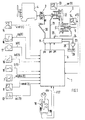
- Fig. 1 shows an overview of an electro-hydraulically operated continuously variable transmission 2 with a controller 1 using the example of a belt transmission.
- the continuously variable transmission 2 is driven by an internal combustion engine 4 via a controllable starting clutch 3.
- An output shaft 5 of the continuously variable transmission 2 is connected to a wheel drive, not shown, of a motor vehicle.
- a control unit 6 controls at least as a function of the throttle valve position alpha (t) of a throttle valve angle sensor 7 and an engine speed nmot (t) of an engine speed sensor 8 of the internal combustion engine 4 to a hydraulic valve block 9.
- the transmission 2 and the starting clutch 3 receive the control unit 6 as further input variables Kick-down signal kd (t) of a kick-down switch 10, an idle signal ll (t) one Idle switch 11, an air quantity or air mass ml (t) of an air quantity or Air mass sensor 12 of the internal combustion engine 4 and a transmission input speed ne (t) one Transmission input speed sensor 13 and a driving speed v (t) one Driving speed sensor 14.
- the gearbox input speed ne (t) corresponds to when the gearbox is closed Starting clutch of the engine speed nmot (t) and can then be used in its place.
- the control unit 6 determines a speed vref (t) Reference speed sensor 15 on a non-driven vehicle axle, one Lateral acceleration aq (t) of a lateral acceleration sensor 16 and a brake signal b (t) one Brake signal generator 17 detected and processed.
- the control is usually carried out by the vehicle driver via a selection device 18
- Preselection of speed levels P (parking lock), R (reverse gear), N (neutral gear) and D (automatic adjustment of the ratio of the continuously variable transmission) can be influenced; furthermore is a Setting range of the selection device 18 is provided for the direct specification of the translation.
- the selector device 18 can be moved from the gear stage D into a second shift gate 19, in which the selector device 18 works as a rocker switch from a central rest position and the driver can influence the translation in the sense of an upshift or a downshift.
- the selector 18 outputs a gear step signal FST and a shift request signal shr for an upshift or a downshift.
- upshifting or “reducing the gear ratio” stands for a gear ratio change that increases the output speed of the transmission while the input speed remains the same, corresponding to an upshifting in a multi-step transmission.
- downshifting and “increasing the gear ratio” stand for a gear change in the sense of a reduction in the output speed of the transmission with the input speed remaining the same, corresponding to a downshift in a multi-step transmission.
- the control device 6 controls via a signal output pk and the valve block 9 the hydraulic pressure in the starting clutch 3 and via signal outputs pe and pa and the hydraulic valve block 9 an actual translation between the Transmission input speed ne (t) and the transmission output speed (driving speed) v (t).
- the hydraulic valve block 9 connects corresponding control lines 20, 21 and 22 of the Starting clutch 3 and the continuously variable transmission 2 with one connected to a pump 23 Pressure line 24 or a return line 25 to a reservoir 26 for hydraulic fluid.
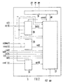
- the control unit 6 comprises, as shown in FIG. 2 , a translation control 27, which is connected to a driving activity determination function 28, a train-push determination function 29, a traction slip determination function 30 and an actuating function 31.
- the driving activity determination function 28 determines the driving style of the driver or the driver traffic-related action in relation to the control of the motor vehicle evaluating size driving activity SK (t), preferably according to one in DE-A1 39 22 051 described method.
- the pull-thrust determination function 29 is a function of the throttle valve position alpha (t) and the engine speed nmot (t) a signal for pulling or pushing the vehicle Pull / push zs (t) ab and the traction slip determination function 30 determines from the difference of Driving speed v (t) and speed vref (t) a slip of the driven wheels representing drive slip san (t).
- the speed step signal FST the shift request signal shr, the Throttle valve position alpha (t), the kick-down signal kd (t), the idle signal ll (t), the Air mass ml (t), the transmission input speed ne (t), the driving speed v (t), the Lateral acceleration aq (t), the brake signal b (t) and the transmission output speed ne (t)
- the translation controller 27 determines a target translation uesoll and a signal Starting clutch on / off AK, which are passed on to the actuating function 31.
- the actuating function 31 controls the setting of the by means of the signal outputs pe and pa Actual gear ratio ue of the transmission 2, the target gear ratio uesoll with the lowest possible Delay time, but is set without noticeable overshoot.
- the Starting clutch according to the signal starting clutch on / off AK from the actuating function 31 controlled via the signal output pk.
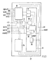
- FIG. 3 shows an overview of the functions contained in the translation control 27.
- An automatic function 32 with the input variables pull / push zs (t), traction slip san (t), driving stage signal FST, driving activity SK (t), throttle valve position alpha (t), engine speed nmot (t), Idle signal ll (t), kick-down signal kd (t), air mass signal ml (t), brake signal b (t) and transmission input speed ne (t) are provided.
- the translation control 27 includes a driving safety function 34 with the Input variables pull / push zs (t) and drive slip san (t). Generate the functions mentioned the output signals target gear ratio uesoll and starting clutch on / off AK.
- a basic function 35 determines the driving activity SK (t) and the switching request signal shr a signal of a first target translation uesoll1.
- the Basic function 35 is followed by a wear reduction function 36, which is derived from the signal derives a signal of a target gear ratio uesoll from the first target gear ratio uesoll1.
- a first transition function 37 and a second transition function 38 affiliated are connected to the automatic function 32.
- Parallel to Basic function 35 is a safety function 39 with the engine speed nmot (t) and outputs the shift request signal shr and the signal clutch on / off AK.
- the basic function 35 contains a table, not shown, in the preset Target translations uesoll1 (i) are stored. Because each of these preset target translations uesoll1 (i) in the simulation of a step transmission a gear of this step transmission corresponds to as many preset target gear ratios uesoll1 (i) as gears a stepped transmission are to be reproduced.
- the preset target gear ratios uesoll1 (i) can therefore also be called gears.
- a 5-speed step transmission is simulated, so that for forward travel the preset target ratios uesoll1 (1), uesoll1 (2), uesoll1 (3), uesoll1 (4) and uesoll1 (5) are stored in the table.
- the designation of the preset target translations follows the scheme uesoll1 (i), where i stands for the corresponding gear of the multi-step transmission.
- uesoll1 (3) stands for the preset target gear ratios that correspond to the 3rd gear of the Gearbox corresponds.
- the value of the preset target gear ratio decreases in this direction: the The preset target ratio is highest for uesoll1 (1) and lowest for uesoll1 (5).
- a matching device 41 is provided for the target translation, which at a recognition device 40 recognized driving situations with too large a jump in translation the target translations uesoll1 (i) preset in the basic function 35 are changed.
- the first transition function 37 becomes when the automatic function 32 changes Manual function 33, i.e. a change from the first to automatically select the translation second operating mode influenced by the driver, called and controls the transition. Vice versa the second transition function controls the transition from manual function 33 to Automatic function 32.
- the adapter 41 monitors the engine speed nmot (t) to see if it is one a minimum differential speed d_nmot_min below a maximum speed nmax Internal combustion engine 4 exceeds the limit. If this condition is also fulfilled, then the adaptation device 41 changes the current target translation uesoll1 (i) by transferring a changed target translation uesoll2 to the basic function 35 so that the Transmission input speed ne (t) is kept constant at the current value. If this is the changed target translation uesoll2 approximately as large as the next lower target translation uesoll1 (i + 1), the basic function 35 changes to the next lower target gear ratio uesoll1 (i + 1) requested.
- a switching request signal shr in any case breaks the work of both the detection device 40 and the Adapter 41; with a switching request signal shr "downshift" takes place under the Condition that a changed target translation uesoll2 has already been set, a transition to originally selected target translation uesoll1 (i).
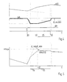
- FIG. 4 shows a diagram of the actual gear ratio ue during the function of the adaptation device 41 and FIG. 5 shows the simultaneous course of the engine speed nmot (t). It can be clearly seen how the driving speed v (t) drops before time t1, although, as not shown, the throttle valve position alpha (t) is large, ie above the limit value g_alpha of approximately 50%. At time t1, a request signal shr "downshift" is issued.
- the recognition device 40 recognizes the predefined driving situation and releases the adaptation value device 41.
- the set actual gear ratio ue is increased after the request signal shr "downshift" from the old value uesoll1 (5) to the new value uesoll1 (4) and subsequently the vehicle speed v (t) and engine speed nmot (t) increase.
- the engine speed nmot reaches a value which is below the maximum speed nmax of the internal combustion engine 4 by the minimum differential speed d_nmot_min.
- the adaptation value device 41 which subsequently keeps the transmission input speed ne (t) constant, takes effect from the time t2.
- the translation ue is continuously increased in accordance with the changed translation setpoint uesoll2.
- the gear ratio ue reaches a value which is a minimum gear ratio difference d_ue_min below the target gear ratio uesoll1 (i + 1) of the next higher gear and automatically initiates an upshift.
- the adaptation device 41 is no longer active, since with the upshift the driving situation recognized by the detection device 40 is no longer present.
- t4 denotes the area in which the actual gear ratio ue remains constant and t5 denotes the area in which the transmission input speed ne (t) is kept constant by the action of the adaptation device 41.
- FIG. 6 shows in a flow chart how the detection device 40 and the adaptation device 41 just described are formed as a function with the aid of a programmable control device.
- the functions of the detection device 40 and the adaptation device 41 which have been shown separately so far are shown together.
- step 42 a signal request signal shr "downshift" is waited for in step 42.
- step 43 the Throttle valve position alpha (t) and driving speed v (t) immediately before the shift be determined.
- step 44 the longitudinal acceleration al (t) is converted from the driving speed v (t) formed and then checked in step 45 whether both the longitudinal acceleration al (t) smaller Zero and the throttle valve position alpha (t) is greater than a limit value g_alpha. Are these If conditions are not met, a step back occurs before step 42.
- step 46 the process continues with step 46 by waiting until the engine speed nmot (t) becomes one Value that results from the maximum speed nmax minus the minimum Differential speed d_nmot_min results. If this is the case, the engine speed is in step 47 nmot kept constant at the current value until the check in Step 48 recognizes that the set actual translation is closer than a minimum Difference value d_ue_min at the target gear ratio in the next higher gear uesoll1 (i + 1). Is if this is the case, a shift request signal shr "upshift" is emitted in step 49 and ended the program.
- the program is ended at any time after step 42 if on after step 42 another switching request signal shr is detected.
- 6 correspond to the Steps 42 to 46 of the recognition device 40 and steps 47 to 49 of the adaptation device 41.
- the translation control 27 operates as follows: Before starting up the translation control 27 are groups of preset translations uesoll1 (1..5) in a not shown Storage filed. During operation, either the automatic function 32 or selected by the manual function 33 the preset translations uesoll1 (i) and set by the actuating function 31 on the transmission 2. Now recognizes the recognition device 40, that before requesting a downshift despite high throttle valve position alpha (t) Driving speed v (t) could not be maintained and additionally after the downshift Internal combustion engine 4 gets close to its maximum speed nmax, so it activates the Adaptation device 41, which by changing the current target translation uesoll1 (4) for this ensures that the engine speed nmot (t) is kept constant.
- the recognition device 40 and the adaptation device 41 as well as the associated procedural steps for representing these facilities in one programmable control device with both automatically switched and from Driver-operated transmissions applicable.
- the automatic function 32 replicates a stage machine and then within the automatic function 35 in an analog A detection device 40 and an adaptation device 41 are provided.
Landscapes
- Engineering & Computer Science (AREA)
- General Engineering & Computer Science (AREA)
- Mechanical Engineering (AREA)
- Control Of Transmission Device (AREA)
Description
- Fig. 1
- eine Übersicht über ein stufenloses Getriebe mit einer Steuerung
- Fig. 2
- ein schematisches Blockschaltbild einer Übersetzungssteuerung,
- Fig. 3
- eine Übersicht über in der Übersetzungssteuerung enthaltene Funktionen,
- Fig. 4
- ein Diagramm der eingestellten Übersetzung während des Wirkens der erfindungsgemäßen Steuereinrichtung,
- Fig. 5
- ein Diagramm des zeitlichen Verlaufes der Drehzahl einer Antriebsmaschine während des Wirkens der erfindungsemäßen Steuervorrichtung und
- Fig. 6
- ein Ablaufdiagramm einer Erkennungs- und Anpaßfunktion.
Hier und im folgenden steht der Begriff "Hochschalten" oder "Verringern der Übersetzung" für eine Übersetzungsänderung, die bei gleichbleibender Eingangsdrehzahl die Ausgangsdrehzahl des Getriebes erhöht, entsprechend einer Hochschaltung bei einem Stufengetriebe. Umgekehrt stehen die Begriffe "Rückschalten" und "Erhöhen der Übersetzung" für eine Übersetzungsänderung im Sinne einer Verringerung der Ausgangsdrehzahl des Getriebes bei gleichbleibender Eingangsdrehzahl, entsprechend einer Rückschaltung bei einem Stufengetriebe.
- Liegt die Drosselklappenstellung alpha(t) oberhalb eines Grenzwertes g_alpha von ca. 50 % ?
- Ist eine aus der Fahrgeschwindigkeit v(t) gebildete (oder extern bereits erfaßte oder extern gebildete) Längsbeschleunigung al(t) < 0?
- 1
- Steuerung
- 2
- stufenloses Getriebe
- 3
- steuerbare Anfahrkupplung
- 4
- Brennkraftmaschine
- 5
- Abtriebswelle
- 6
- Steuergerät
- 7
- Drosselklappenwinkelgeber
- 8
- Motordrehzahlgeber
- 9
- Hydraulik-Ventilblock
- 10
- Kick-down-Schalters
- 11
- Leerlaufschalters
- 12
- Luftmengen- bzw. Luftmassengeber
- 13
- Getriebeeingangsdrehzahlgeber
- 14
- Fahrgeschwindigkeitgeber
- 15
- Referenzgeschwindigkeitgeber
- 16
- Querbeschleunigungsgeber
- 17
- Bremssignalgeber
- 18
- Wähleinrichtung
- 19
- zweite Schaltgasse
- 20
- Steuerleitung
- 21
- Steuerleitung
- 22
- Steuerleitung
- 23
- Pumpe
- 24
- Druckleitung
- 25
- Rücklaufleitung
- 26
- Vorratsbehälter
- 27
- Übersetzungssteuerung
- 28
- Fahraktivitätsermittlungfunktion
- 29
- Zug-Schub-Ermittlungsfunktion
- 30
- Antriebsschlupfermittlungsfunktion
- 31
- Stellfunktion
- 32
- Automatikfunktion
- 33
- Manuellfunktion
- 34
- Fahrsicherheitsfunktion
- 35
- Grundfunktion
- 36
- Verschleißminderungsfunktion
- 37
- erste Übergangsfunktion
- 38
- zweite Übergangsfunktion
- 39
- Sicherheitsfunktion
- 40
- Erkennungsfunktion
- 41
- Anpaßfunktion
- AK
- Signal Anfahrkupplung auf/zu
- alpha(t)
- Drosselklappenstellung
- aq(t)
- Querbeschleunigung
- b(t)
- Bremssignal
- D
- Fahrstufe "selbsttätige Übersetzungseinstellung"
- d_nmot_min
- minimale Differenzdrehzahl
- d_ue_min
- minimale Übersetzungsdifferenz
- FST
- Fahrstufensignal
- g_alpha
- Grenzwert für Drosselklappenstellung
- kd(t)
- Kick-down-Signal
- II(t)
- Leerlaufsignal
- ml(t)
- Luftmenge bzw. Luftmasse
- N
- Fahrstufe "Leergangstufe"
- na(t)
- Getriebeausgangsdrehzahl
- ne(t)
- Getriebeeingangsdrehzahl
- nmax
- maximale Motordrehzahl
- nmot(t)
- Motordrehzahl
- P
- Fahrstufe "Parksperre"
- pa
- Signalausgang
- pe
- Signalausgang
- pk
- Signalausgang
- R
- Fahrstufe "Rückwärtsgangstufe"
- san(t)
- Antriebsschlupf
- shr
- Schaltanforderungssignal
- SK(t)
- Fahraktivität
- t1..t3
- Zeitpunkte
- t4..t5
- Zeiträume
- ue
- Ist-Übersetzung
- uesoll
- Soll-Übersetzung
- uesoll1(i)
- voreingestellte Soll-Übersetzungen
- uesoll2
- 2 Veränderte Soll-Übersetzung
- v(t)
- Fahrgeschwindigkeit
- vref(t)
- Geschwindigkeit
- zs(t)
- Zug/Schub
Claims (22)
- Steuereinrichtung (6) für ein stufenloses Getriebes (2) eines insbesondere mit einer Brennkraftmaschine (4) angetriebenen Kraftfahrzeuges, wobei die Steuereinrichtung (6) mit einer Wähleinrichtung (18) versehen ist und die Steuereinrichtung (6) ein gestuftes Getriebe nachbildet, indem die Steuereinrichtung (6) aus einer Gruppe von voreingestellten Übersetzungen (uesoll1(1..5)) ausgewählte Übersetzungen (uesoll1(i)) im Getriebe einstellt, dadurch gekennzeichnet, daß die Steuereinrichtungeine Erkennungseinrichtung (40) für Fahrsituationen, in denen der Übersetzungssprung für einen herrschenden Fahrwiderstand zu groß ist, undeine Anpaßeinrichtung (41) für die ausgewählte Übersetzung (uesoll1(i)) oder eine benachbarte Übersetzung (uesoll1(i+1)) aufweist, die eine ausgewählte Übersetzung so verändert, daß die Zugkraft dem herrschenden Fahrwiderstand angepaßt ist, unddie Erkennungseinrichtung (40) die Anpaßeinrichtung (41) aktiviert.
- Steuereinrichtung nach Anspruch 1, dadurch gekennzeichnet, daß die Erkennungseinrichtung (40) anspricht, wenn vor einem Wechsel von einer voreingestellten Übersetzung (uesoll1(5)) zu einer nächsthöheren voreingestellten Übersetzung (uesoll1(4)) eine Drosselklappenstellung (alpha(t)) größer als ein Grenzwert (g_alpha) und eine Längsbeschleunigung (al(t)) kleiner als Null ist.
- Steuereinrichtung nach Anspruch 1 oder 2, dadurch gekennzeichnet, daß die Anpaßeinrichtung (41) eine veränderte Übersetzung (uesoll2) so einstellt, daß eine Getriebeeingangsdrehzahl (ne(t)) konstant bleibt, wenn eine Motordrehzahl (nmot(t)) größer als ein Grenzwert (nmax - d_nmot_min) ist.
- Steuereinrichtung nach Anspruch 3, dadurch gekennzeichnet, daß ein selbsttätiger Wechsel zur nächstniedrigeren voreingestellten Übersetzung (uesoll1(5)) erfolgt, sobald eine vorgegebene Drehzahldifferenz (d_nmot_min) zur Motordrehzahl (nmot(t)) in der nächstniedrigeren voreingestellten Übersetzung (uesoll1(5)) unterschritten wird.
- Steuereinrichtung nach Anspruch 3, dadurch gekennzeichnet, daß ein selbsttätiger Wechsel zur nächstniedrigeren voreingestellten Übersetzung (uesoll1(5)) erfolgt, sobald dort bei der aktuell vorliegenden Drosselklappenstellung (alpha(t) und Motordrehzahl (nmot(t)) Zugkraftüberschuß herrscht.
- Steuereinrichtung nach Anspruch 1 oder 2, dadurch gekennzeichnet, daß die Anpaßeinrichtung (41) die bei einem Wechsel von einer voreingestellten Übersetzung (uesoll1(5)) zu einer nächsthöheren voreingestellten Übersetzung (uesoll1(4)) einzustellende nächsthöhere voreingestellte Übersetzung (uesoll1(4)) durch eine veränderte Übersetzung (uesoll2) ersetzt, die so gewählt ist, daß ein Betrieb der Brennkraftmaschine (4) über ein vorgegebenes Motordrehzahlband (nmot(t)) möglich ist.
- Steuereinrichtung nach Anspruch 6, dadurch gekennzeichnet, daß die veränderte Übersetzung (uesoll2) so gewählt ist, daß ein Betrieb der Brennkraftmaschine (4) über ein vorgegebenes Motordrehzahlband (nmot(t)) unter Zugkraftüberschuß möglich ist.
- Steuereinrichtung nach Anspruch 1, dadurch gekennzeichnet, daß die Erkennungseinrichtung (40) anspricht, wenn in der nächstniedrigeren voreingestellten Übersetzung (uesoll1(5)) bei der aktuell vorliegenden Drosselklappenstellung (alpha(t)) und Motordrehzahl (nmot(t)) kein Zugkraftüberschuß herrscht.
- Steuereinrichtung nach Anspruch 1 oder 8, dadurch gekennzeichnet, daß die Anpaßeinrichtung (41) einen Wechsel zur nächstniedrigeren voreingestellten Übersetzung (uesoll1(5)) unterdrückt, bis dort bei der aktuell vorliegenden Drosselklappenstellung (alpha(t) und Motordrehzahl (nmot(t)) Zugkraftüberschuß herrscht, und während der Unterdrückung dieses Wechsels eine veränderte Übersetzung (uesoll2) so einstellt, daß eine Getriebeeingangsdrehzahl (ne(t)) konstant bleibt, wenn eine Motordrehzahl (nmot(t)) größer als ein Grenzwert (nmax - d_nmot_min) ist.
- Steuereinrichtung nach Anspruch 1 oder 8, dadurch gekennzeichnet, daß die Anpaßeinrichtung (41) die nächstniedrigere voreingestellte Übersetzung (uesoll1(5))durch eine veränderte Übersetzung (uesoll2) ersetzt, die so gewählt ist, daß dort bei der aktuell vorliegenden Drosselklappenstellung (alpha(t) und Motordrehzahl (nmot(t)) Zugkraftüberschuß herrscht.
- Steuereinrichtung nach einem der vorhergehenden Ansprüche, dadurch gekennzeichnet, daß die Anpaßeinrichtung (41) nach ihrer Deaktivierung die zuletzt eingestellte veränderte Übersetzung (uesoll2) bis zur nächsten Schaltung beibehält, wobei bei einer Rückschaltung die ursprünglich eingestellte Übersetzung (uesoll1(i)) wieder eingestellt wird.
- Steuerverfahren für ein stufenloses Getriebe (2) eines insbesondere mit einer Brennkraftmaschine (4) angetriebenen Kraftfahrzeuges, wobei eine das Steuerverfahren ausführende Steuereinrichtung (6) mit einer Wähleinrichtung (18) versehen ist und die Steuereinrichtung (6) ein gestuftes Getriebe nachbildet, indem die Steuereinrichtung (6) aus einer Gruppe von voreingestellten Übersetzungen (uesoll1(1..5)) ausgewählte Übersetzungen (uesoll1(i)) im Getriebe einstellt, gekennzeichnet durch folgende Schritte:Erkennen einer Fahrsituation (45-47), in der der Übersetzungssprung für einen herrschenden Fahrwiderstand zu groß ist, und nachfolgendAnpassen einer ausgewählten Übersetzung (uesoll1(4)) so, daß die Zugkraft in dieser ausgewählten oder der hierzu benachbarten Übersetzung (uesoll1(4) oder uesoll1(5)) dem herrschenden Fahrwiderstand entspricht.
- Steuerverfahren nach Anspruch 12, gekennzeichnet durch folgende Schritte für das Erkennen einer Fahrsituation, in der der Übersetzungssprung für einen herrschenden Fahrwiderstand zu groß ist:Abwarten Schaltanforderungssignal (shr) "Rückschalten" (42),Ermitteln der Drosselklappenstellung alpha(t) und der Längsbeschleunigung al(t) unmittelbar vor der Rückschaltung (43,44),Prüfen ob sowohl die Längsbeschleunigung (al(t)) kleiner Null als auch die Drosselklappenstellung (alpha(t)) größer als ein Grenzwert (g_alpha) ist (45),wenn ja, dann weiter mit dem Anpassen der ausgewählten Übersetzung.,
- Steuerverfahren nach einem der Ansprüche 12 oder 13, gekennzeichnet durch folgenden Schritt für das Anpassen der ausgewählten Übersetzung (uesoll1(4)):Abwarten bis die Motordrehzahl (nmot(t)) einen Grenzwert (nmax - d_nmot_min) überschreitet (46) und nachfolgendEinstellen einer veränderten Übersetzung (uesoll2) so, daß die Getriebeeingangsdrehzahl (ne(t)) konstant gehalten ist (47).
- Steuerverfahren nach Anspruch 14, gekennzeichnet durch die folgenden Schritte:Prüfen, ob die veränderte Übersetzung (uesoll2) größer als ein Grenzwert (uesoll1' - d_ue_min) ist (48) undwenn ja, Abgeben eines Schaltanforderungssignal (shr) "Hochschalten".
- Steuerverfahren nach Anspruch 14, gekennzeichnet durch die folgenden Schritte:Prüfen, ob in der nächstniedrigeren Übersetzung (uesoll1(5)) ein Betrieb der Brennkraftmaschine (4) bei der aktuell vorliegenden Drosselklappenstellung (alpha(t) und Motordrehzahl (nmot(t)) unter Zugkraftüberschuß möglich ist undwenn ja, Abgeben eines Schaltanforderungssignal shr "Hochschalten".
- Steuerverfahren nach Anspruch 12 oder 13, gekennzeichnet durch folgenden Schritt für das Anpassen der ausgewählten Übersetzung (uesoll1(i)):Einstellen einer veränderten nächsthöheren Übersetzung (uesoll2) so, daß dort ein Betrieb der Brennkraftmaschine (4) über ein vorgegebenes Drehzahlband (nmot(t)) möglich ist.
- Steuerverfahren nach Anspruch 12 oder 13, gekennzeichnet durch folgenden Schritt für das Einstellen einer veränderten nächsthöheren Übersetzung (uesoll2):Einstellen einer veränderten nächsthöheren Übersetzung (uesoll2) so, daß dort ein Betrieb der Brennkraftmaschine über ein vorgegebenes Drehzahlband und unter Zugkraftüberschuß möglich ist.
- Steuerverfahren nach Anspruch 12, gekennzeichnet durch folgende Schritte für das Erkennen einer Fahrsituation, in der der Übersetzungssprung für einen herrschenden Fahrwiderstand zu groß ist:Prüfen, ob in einer nächstniedrigeren voreingestellten Übersetzung (uesoll1(5)) bei der aktuell vorliegenden Drosselklappenstellung (alpha(t) und Motordrehzahl (nmot(t)) Zugkraftüberschuß herrscht undwenn ja, dann weiter mit dem Anpassen der ausgewählten Übersetzung.
- Steuerverfahren nach Anspruch 12 oder 19, gekennzeichnet durch durch folgenden Schritt für das Anpassen der ausgewählten Übersetzung (uesoll1(4)):Prüfen, ob in der nächstniedrigeren voreingestellten Übersetzung (uesoll1(5)) bei der aktuell vorliegenden Drosselklappenstellung (alpha(t) und Motordrehzahl (nmot(t)) Zugkraftüberschuß herrscht, und solange die Prüfung nein ergibt,Unterdrücken eines Wechsels zur nächstniedrigeren voreingestellten Übersetzung (uesoll1(5)) undEinstellen einer veränderten Übersetzung (uesoll2) so, daß eine Getriebeeingangsdrehzahl (ne(t)) konstant bleibt, wenn eine Motordrehzahl (nmot(t)) größer als ein Grenzwert (nmax - d_nmot_min) ist.
- Steuerverfahren nach Anspruch 12 oder 19, gekennzeichnet durch durch folgenden Schritt für das Anpassen der ausgewählten Übersetzung (uesoll1(4)):Einstellen einer veränderten nächstniedrigeren Übersetzung (uesoll2) so, daß dort bei der aktuell vorliegenden Drosselklappenstellung (alpha(t) und Motordrehzahl (nmot(t)) Zugkraftüberschuß herrscht.
- Steuerverfahren einem der Ansprüche 12 bis 21, dadurch gekennzeichnet, daß das Steuerverfahren zu jedem Zeitpunkt nach dem Abwarten des Schaltanforderungssignales (shr) "Rückschalten" (42) beendet wird, wenn ein weiteres Schaltanforderungssignal (shr) erkannt wird.
Applications Claiming Priority (2)
| Application Number | Priority Date | Filing Date | Title |
|---|---|---|---|
| DE4411938 | 1994-04-07 | ||
| DE4411938A DE4411938A1 (de) | 1994-04-07 | 1994-04-07 | Steuereinrichtung und Steuerverfahren für ein stufenloses Getriebe |
Publications (3)
| Publication Number | Publication Date |
|---|---|
| EP0676564A2 EP0676564A2 (de) | 1995-10-11 |
| EP0676564A3 EP0676564A3 (de) | 1997-10-29 |
| EP0676564B1 true EP0676564B1 (de) | 2000-01-26 |
Family
ID=6514796
Family Applications (1)
| Application Number | Title | Priority Date | Filing Date |
|---|---|---|---|
| EP95103170A Expired - Lifetime EP0676564B1 (de) | 1994-04-07 | 1995-03-06 | Steuereinrichtung und Steuerverfahren für ein stufenloses Getriebe |
Country Status (6)
| Country | Link |
|---|---|
| US (1) | US5655991A (de) |
| EP (1) | EP0676564B1 (de) |
| JP (1) | JP3605172B2 (de) |
| KR (1) | KR100314231B1 (de) |
| DE (2) | DE4411938A1 (de) |
| ES (1) | ES2141269T3 (de) |
Families Citing this family (26)
| Publication number | Priority date | Publication date | Assignee | Title |
|---|---|---|---|---|
| KR970021130A (ko) * | 1995-10-23 | 1997-05-28 | 카르크, 비베르바흐 | 디히드로푸란 유도체의 방사선 경화 |
| JP3633063B2 (ja) * | 1995-11-07 | 2005-03-30 | マツダ株式会社 | 自動変速機の制御装置 |
| JP3491423B2 (ja) * | 1996-01-16 | 2004-01-26 | 日産自動車株式会社 | 無段変速機の変速制御装置 |
| JP3424423B2 (ja) * | 1996-02-08 | 2003-07-07 | 日産自動車株式会社 | 無段自動変速機の変速制御装置 |
| JP3513314B2 (ja) * | 1996-02-20 | 2004-03-31 | 富士重工業株式会社 | 車両用無段変速装置の制御装置 |
| KR970066191A (ko) * | 1996-03-01 | 1997-10-13 | 가나이 쯔도무 | 자동 변속기의 제어 장치 및 제어 방법 |
| JP3911749B2 (ja) * | 1996-03-29 | 2007-05-09 | マツダ株式会社 | 自動変速機の制御装置 |
| BE1010795A3 (nl) * | 1996-12-10 | 1999-02-02 | Vcst Nv | Werkwijze en inrichting voor het sturen van de overbrengingsverhouding van een riemvariator bij een transmissie-eenheid voor een motorvoertuig. |
| JP3395581B2 (ja) * | 1997-06-24 | 2003-04-14 | 日産自動車株式会社 | 無段変速機の変速制御装置 |
| JP3374753B2 (ja) * | 1997-07-25 | 2003-02-10 | 日産自動車株式会社 | 車両用無段変速機の変速制御方法 |
| GB9720172D0 (en) * | 1997-09-24 | 1997-11-26 | Rover Group | A transmission control system for a vehicle |
| DE19831514A1 (de) | 1998-07-14 | 2000-01-20 | Bayerische Motoren Werke Ag | Steuerverfahren und Steuervorrichtung für ein stufenloses Getriebe |
| JP3547709B2 (ja) | 1998-10-23 | 2004-07-28 | シーメンス アクチエンゲゼルシヤフト | 車両のオートマティック無段変速機の制御方法および制御装置 |
| US6368247B1 (en) * | 1999-04-28 | 2002-04-09 | Mitsubishi Jidosha Kogyo Kabushiki | Speed ratio control system for continuously variable transmission |
| DE19921500A1 (de) | 1999-05-08 | 2000-11-09 | Zahnradfabrik Friedrichshafen | Verfahren zur manuellen Vorgabe der Übersetzung eines stufenlosen Getriebes |
| DE19943332A1 (de) * | 1999-09-10 | 2001-03-15 | Zahnradfabrik Friedrichshafen | Verfahren zur Regelung der Fahrzeugbeschleunigung für ein Kraftfahrzeug mit einem stufenlosen Automatgetriebe |
| JP4101450B2 (ja) * | 2000-09-27 | 2008-06-18 | ジヤトコ株式会社 | 無段変速機の発進時変速制御装置 |
| FR2822972B1 (fr) * | 2001-03-29 | 2003-07-18 | Renault | Dispositif d'estimation de la charge d'un vehicule et vehicule a transmission automatique utilisant un tel dispositif |
| JP3794483B2 (ja) * | 2002-06-05 | 2006-07-05 | 本田技研工業株式会社 | 車両用無段変速機の制御装置 |
| JP4376034B2 (ja) * | 2003-11-04 | 2009-12-02 | 本田技研工業株式会社 | 車両用無段変速機の制御装置 |
| DE102006030528A1 (de) * | 2006-07-01 | 2008-01-03 | Zf Friedrichshafen Ag | Vorausschauende Bestimmung einer Übersetzungsänderung |
| US8052572B2 (en) * | 2007-04-27 | 2011-11-08 | Yamaha Hatsudoki Kabushiki Kaisha | Control device of straddle-type vehicle, transmission, and straddle-type vehicle |
| EP2156073B1 (de) * | 2007-06-08 | 2018-11-14 | Volvo Lastvagnar AB | Verfahren zur einstellung einer automatisch gewählten gangschaltdrehzahlbegrenzung in einem fahrzeug |
| DE102010061279B4 (de) | 2009-12-25 | 2021-09-23 | Subaru Corporation | Stufenlos verstellbare Getriebe |
| DE102011087771A1 (de) * | 2011-12-06 | 2013-06-06 | Zf Friedrichshafen Ag | Steuerungseinrichtung eines Kraftfahrzeugs |
| US8874332B2 (en) * | 2012-11-01 | 2014-10-28 | Caterpillar Inc. | Shifting virtual gears associated with a continuously variable transmission |
Citations (1)
| Publication number | Priority date | Publication date | Assignee | Title |
|---|---|---|---|---|
| EP0588828A1 (de) * | 1991-06-21 | 1994-03-30 | Porsche Ag | Verfahren zum steuern eines stufenlosen getriebes. |
Family Cites Families (17)
| Publication number | Priority date | Publication date | Assignee | Title |
|---|---|---|---|---|
| EP0123083B1 (de) * | 1983-03-11 | 1987-11-04 | Nissan Motor Co., Ltd. | Steuerungssystem und Steuerungsverfahren für ein Kraftfahrzeug |
| JPS6044649A (ja) * | 1983-08-22 | 1985-03-09 | Toyota Motor Corp | 車両用無段変速機の制御方法 |
| JPS6053261A (ja) * | 1983-09-01 | 1985-03-26 | Toyota Motor Corp | 車両用無段変速機の速度比制御装置 |
| JPS6127357A (ja) * | 1984-07-18 | 1986-02-06 | Toyota Motor Corp | 車両用無段変速機の制御装置 |
| JPS61249833A (ja) * | 1985-04-30 | 1986-11-07 | Fuji Heavy Ind Ltd | 4輪駆動装置の油圧制御装置 |
| US4788892A (en) * | 1985-05-11 | 1988-12-06 | Toyota Jidosha Kabushiki Kaisha | Controller for automatic transmission |
| DE3771361D1 (de) * | 1986-03-17 | 1991-08-22 | Isuzu Motors Ltd | Steuervorrichtung fuer selbsttaetiges uebersetzungsgetriebe. |
| JPS6353130A (ja) * | 1986-08-23 | 1988-03-07 | Fuji Heavy Ind Ltd | 無段変速機の制御装置 |
| US5079704A (en) * | 1988-11-18 | 1992-01-07 | Honda Giken Kogyo Kabushiki Kaisha | Vehicle automatic transmission control system |
| JPH0729556B2 (ja) * | 1988-12-23 | 1995-04-05 | 日産自動車株式会社 | 四輪駆動車の駆動力配分制御装置 |
| JP2701429B2 (ja) * | 1989-03-03 | 1998-01-21 | 三菱電機株式会社 | 自動変速機の制御装置 |
| DE4010104C3 (de) * | 1989-03-29 | 1997-12-04 | Nissan Motor | Schaltsteuersystem für ein ein automatisches Getriebe aufweisendes Fahrzeug |
| JPH03189461A (ja) * | 1989-12-18 | 1991-08-19 | Mazda Motor Corp | 無段変速機の変速比制御装置 |
| JP2778251B2 (ja) * | 1991-04-02 | 1998-07-23 | 三菱自動車工業株式会社 | 内燃機関と連続可変変速機との制御装置 |
| DE4120602C2 (de) * | 1991-06-21 | 1995-02-02 | Porsche Ag | Verfahren zur selbsttätigen Steuerung einer drehzahlwandelnden Anfahreinrichtung eines Kraftfahrzeugs |
| DE4120552C1 (de) * | 1991-06-21 | 1992-12-17 | Dr.Ing.H.C. F. Porsche Ag, 7000 Stuttgart, De | |
| DE4324091C2 (de) * | 1993-07-17 | 1998-11-26 | Porsche Ag | Verfahren und Vorrichtung zum Steuern eines automatischen Getriebes |
-
1994
- 1994-04-07 DE DE4411938A patent/DE4411938A1/de not_active Withdrawn
-
1995
- 1995-03-06 EP EP95103170A patent/EP0676564B1/de not_active Expired - Lifetime
- 1995-03-06 DE DE59507668T patent/DE59507668D1/de not_active Expired - Lifetime
- 1995-03-06 ES ES95103170T patent/ES2141269T3/es not_active Expired - Lifetime
- 1995-04-06 KR KR1019950007923A patent/KR100314231B1/ko not_active Expired - Lifetime
- 1995-04-07 JP JP08294095A patent/JP3605172B2/ja not_active Expired - Lifetime
- 1995-04-07 US US08/418,613 patent/US5655991A/en not_active Expired - Lifetime
Patent Citations (1)
| Publication number | Priority date | Publication date | Assignee | Title |
|---|---|---|---|---|
| EP0588828A1 (de) * | 1991-06-21 | 1994-03-30 | Porsche Ag | Verfahren zum steuern eines stufenlosen getriebes. |
Also Published As
| Publication number | Publication date |
|---|---|
| JPH0886341A (ja) | 1996-04-02 |
| DE59507668D1 (de) | 2000-03-02 |
| ES2141269T3 (es) | 2000-03-16 |
| EP0676564A2 (de) | 1995-10-11 |
| EP0676564A3 (de) | 1997-10-29 |
| JP3605172B2 (ja) | 2004-12-22 |
| DE4411938A1 (de) | 1995-10-12 |
| KR950033196A (ko) | 1995-12-22 |
| US5655991A (en) | 1997-08-12 |
| KR100314231B1 (ko) | 2002-02-19 |
Similar Documents
| Publication | Publication Date | Title |
|---|---|---|
| EP0676564A2 (de) | Steuereinrichtung und Steuerverfahren für ein stufenloses Getriebe | |
| EP1899190B1 (de) | Verfahren zum steuern eines antriebsstranges eines fahrzeugs mit einer antriebsmaschine und mit einem getriebe | |
| EP0406616B1 (de) | Verfahren und Vorrichtung zur Steuerung eines selbsttätig schaltenden Getriebes | |
| EP0588896B1 (de) | Verfahren zur steuerung eines automatisch betätigten getriebes eines kraftfahrzeugs | |
| EP0713985B1 (de) | Steuereinrichtung und Steuerverfahren für ein stufenloses Getriebe | |
| DE69522797T2 (de) | Verfahren zur regelung der geschwindigkeitsänderung für ein elektrisches fahrzeug | |
| DE4239133C1 (de) | Steuereinrichtung für ein stufenloses Getriebe | |
| EP0587614B1 (de) | Verfahren zur steuerung eines stufenlosen kraftfahrzeuggetriebes | |
| EP0670789B1 (de) | Verfahren zur steuerung des abtriebsmoments eines automatischen schaltgetriebes | |
| EP0589919B1 (de) | Verfahren zur steuerung eines stufenlosen getriebes eines kraftfahrzeugs | |
| DE4120603C2 (de) | Steuereinrichtung für ein selbsttätig schaltendes Getriebe eines Kraftfahrzeugs | |
| WO1993000229A1 (de) | Verfahren zur steuerung eines stufenlosen getriebes eines kraftfahrzeugs | |
| DE4324091C2 (de) | Verfahren und Vorrichtung zum Steuern eines automatischen Getriebes | |
| DE4120566C2 (de) | Steuereinrichtung für ein selbsttätig schaltendes Getriebe eines Kraftfahrzeugs | |
| DE19714946B4 (de) | Verfahren und Vorrichtung zum Steuern der Bergabfahrt eines Fahrzeugs | |
| EP0676565B1 (de) | Steuerverfahren und Steuereinrichtung für ein stufenloses Getriebe | |
| EP0974019B1 (de) | Erhöhung der spontanität eines automatgetriebes | |
| EP0713984B1 (de) | Verfahren zur Bestimmung der Schaltzeit für einen Übersetzungswechsel in einem stufenlosen Getriebe | |
| EP0728612A2 (de) | Regeleinrichtung für ein stufenlos einstellbares Getriebe für Kraftfahrzeuge | |
| DE69809236T2 (de) | Verfahren zum steuern der zurückschaltungsgänge bei automatikgetrieben | |
| DE3801362C2 (de) | Steuereinrichtung für hydraulisch betätbares Fahrzeuggetriebe | |
| DE19831514A1 (de) | Steuerverfahren und Steuervorrichtung für ein stufenloses Getriebe | |
| DE4006062A1 (de) | Schaltsteuersystem fuer ein automatisches getriebe mit verbesserter schaltuebergangscharakteristik | |
| EP0713986B1 (de) | Steuereinrichtung und Steuerverfahren für ein stufenloses Getriebe | |
| DE4039840A1 (de) | Schaltsteuereinrichtung fuer ein automatisches kraftfahrzeuggetriebe und ein verfahren hierfuer |
Legal Events
| Date | Code | Title | Description |
|---|---|---|---|
| PUAI | Public reference made under article 153(3) epc to a published international application that has entered the european phase |
Free format text: ORIGINAL CODE: 0009012 |
|
| AK | Designated contracting states |
Kind code of ref document: A2 Designated state(s): DE ES FR GB NL |
|
| PUAL | Search report despatched |
Free format text: ORIGINAL CODE: 0009013 |
|
| AK | Designated contracting states |
Kind code of ref document: A3 Designated state(s): DE ES FR GB NL |
|
| 17P | Request for examination filed |
Effective date: 19980407 |
|
| GRAG | Despatch of communication of intention to grant |
Free format text: ORIGINAL CODE: EPIDOS AGRA |
|
| GRAG | Despatch of communication of intention to grant |
Free format text: ORIGINAL CODE: EPIDOS AGRA |
|
| GRAH | Despatch of communication of intention to grant a patent |
Free format text: ORIGINAL CODE: EPIDOS IGRA |
|
| 17Q | First examination report despatched |
Effective date: 19990714 |
|
| GRAH | Despatch of communication of intention to grant a patent |
Free format text: ORIGINAL CODE: EPIDOS IGRA |
|
| GRAA | (expected) grant |
Free format text: ORIGINAL CODE: 0009210 |
|
| AK | Designated contracting states |
Kind code of ref document: B1 Designated state(s): DE ES FR GB NL |
|
| REF | Corresponds to: |
Ref document number: 59507668 Country of ref document: DE Date of ref document: 20000302 |
|
| REG | Reference to a national code |
Ref country code: ES Ref legal event code: FG2A Ref document number: 2141269 Country of ref document: ES Kind code of ref document: T3 |
|
| ET | Fr: translation filed | ||
| GBT | Gb: translation of ep patent filed (gb section 77(6)(a)/1977) |
Effective date: 20000428 |
|
| PLBE | No opposition filed within time limit |
Free format text: ORIGINAL CODE: 0009261 |
|
| STAA | Information on the status of an ep patent application or granted ep patent |
Free format text: STATUS: NO OPPOSITION FILED WITHIN TIME LIMIT |
|
| 26N | No opposition filed | ||
| REG | Reference to a national code |
Ref country code: GB Ref legal event code: IF02 |
|
| REG | Reference to a national code |
Ref country code: FR Ref legal event code: TP |
|
| REG | Reference to a national code |
Ref country code: FR Ref legal event code: CD |
|
| REG | Reference to a national code |
Ref country code: FR Ref legal event code: TP |
|
| REG | Reference to a national code |
Ref country code: GB Ref legal event code: 732E Free format text: REGISTERED BETWEEN 20110310 AND 20110316 |
|
| REG | Reference to a national code |
Ref country code: GB Ref legal event code: 732E Free format text: REGISTERED BETWEEN 20110331 AND 20110406 |
|
| PGFP | Annual fee paid to national office [announced via postgrant information from national office to epo] |
Ref country code: NL Payment date: 20110316 Year of fee payment: 17 |
|
| PGFP | Annual fee paid to national office [announced via postgrant information from national office to epo] |
Ref country code: GB Payment date: 20110321 Year of fee payment: 17 Ref country code: ES Payment date: 20110325 Year of fee payment: 17 |
|
| REG | Reference to a national code |
Ref country code: NL Ref legal event code: V1 Effective date: 20121001 |
|
| GBPC | Gb: european patent ceased through non-payment of renewal fee |
Effective date: 20120306 |
|
| PG25 | Lapsed in a contracting state [announced via postgrant information from national office to epo] |
Ref country code: GB Free format text: LAPSE BECAUSE OF NON-PAYMENT OF DUE FEES Effective date: 20120306 |
|
| PG25 | Lapsed in a contracting state [announced via postgrant information from national office to epo] |
Ref country code: NL Free format text: LAPSE BECAUSE OF NON-PAYMENT OF DUE FEES Effective date: 20121001 |
|
| REG | Reference to a national code |
Ref country code: ES Ref legal event code: FD2A Effective date: 20130710 |
|
| PG25 | Lapsed in a contracting state [announced via postgrant information from national office to epo] |
Ref country code: ES Free format text: LAPSE BECAUSE OF NON-PAYMENT OF DUE FEES Effective date: 20120307 |
|
| PGFP | Annual fee paid to national office [announced via postgrant information from national office to epo] |
Ref country code: DE Payment date: 20140304 Year of fee payment: 20 |
|
| PGFP | Annual fee paid to national office [announced via postgrant information from national office to epo] |
Ref country code: FR Payment date: 20140319 Year of fee payment: 20 |
|
| REG | Reference to a national code |
Ref country code: DE Ref legal event code: R071 Ref document number: 59507668 Country of ref document: DE |