EP0676719B1 - Vorrichtung zur Darstellung von Bildern - Google Patents
Vorrichtung zur Darstellung von Bildern Download PDFInfo
- Publication number
- EP0676719B1 EP0676719B1 EP95105312A EP95105312A EP0676719B1 EP 0676719 B1 EP0676719 B1 EP 0676719B1 EP 95105312 A EP95105312 A EP 95105312A EP 95105312 A EP95105312 A EP 95105312A EP 0676719 B1 EP0676719 B1 EP 0676719B1
- Authority
- EP
- European Patent Office
- Prior art keywords
- draw
- offset
- image
- command
- commands
- Prior art date
- Legal status (The legal status is an assumption and is not a legal conclusion. Google has not performed a legal analysis and makes no representation as to the accuracy of the status listed.)
- Expired - Lifetime
Links
Images


Classifications
-
- G—PHYSICS
- G06—COMPUTING OR CALCULATING; COUNTING
- G06T—IMAGE DATA PROCESSING OR GENERATION, IN GENERAL
- G06T11/00—Two-dimensional [2D] image generation
-
- G—PHYSICS
- G06—COMPUTING OR CALCULATING; COUNTING
- G06T—IMAGE DATA PROCESSING OR GENERATION, IN GENERAL
- G06T1/00—General purpose image data processing
- G06T1/60—Memory management
-
- G—PHYSICS
- G06—COMPUTING OR CALCULATING; COUNTING
- G06T—IMAGE DATA PROCESSING OR GENERATION, IN GENERAL
- G06T3/00—Geometric image transformations in the plane of the image
Definitions
- the present invention relates to an apparatus for generating images suitable for use with apparatuses utilizing computer graphics such as video game machines and graphic computers which must perform a high level of visualization using limited hardware resources.
- a drawing device portion is provided between the CPU and frame buffer (frame memory) in order to improve the processing speed.
- the CPU does not directly access the frame buffer, but generates commands to draw basic figures such as triangles and quadrangles and sends them to the drawing device portion.
- the drawing device portion interprets those commands from the CPU and draws the figures on the frame buffer.
- the smallest unit of figure processed by the drawing device portion is referred to as a polygon or primitive and a command to draw it is referred to as a draw command or display list.
- a 3D (three-dimensional) graphics system in which an object is drawn on a two-dimensional display screen with a three-dimensional appearance, the surface of the 3D object to be rendered is divided into a plurality of polygons, and the polygons are sequentially drawn on a frame buffer to reconstruct an image having a three-dimensional appearance.
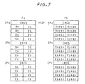
- the coordinates of the vertices of the respective polygons Pa, Pb, and Pc are added to respective indication codes INCO indicating that the subsequent data is polygon draw commands.
- JP 7085308 (published on March 31, 1995) JP 7073333 (published on March 17, 1995) JP 7114654 (published on May 2, 1995) JP 7219894 (published on August 18, 1995)
- the EP-A-0 676 722 which forms prior art according to Art.54(3) EPC, describes an image generating method and apparatus wherein drawing instructions and control instructions generated by a CPU are transferred to a drawing device section which generates an image by sequentially performing drawing operations in accordance with the drawing instructions and the control instructions.
- An image generation apparatus comprises the features of the appended claim 1.
- the apparatus for generating images of the present invention when an image of a 3D object or the like is translated on a display screen, it is necessary only to rewrite the offset values for the coordinates of the vertices in the offset draw command that precedes the string of draw commands. This minimizes access to the main memory and makes it possible to perform the translation process at high speed.
- the offset draw command and the draw commands constituting the string can be obtained in a linked form in the order in which they are to be executed.
- the present invention minimizes access to the main memory during a translation of an image of a 3D object or the like on a display screen to allow the translation process to be performed at high speed.
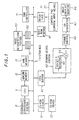
- Fig. 1 is a block diagram of an image generation apparatus according to an embodiment of the present invention.
- Fig. 2 illustrates an example of the configuration of offset draw commands and polygon draw commands in the case of a translation of an object.
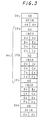
- Fig. 3 illustrates another example of the configuration of offset draw commands and polygon draw commands in the case of a translation of an object.
- Fig. 4 illustrates an example of a method of dividing one frame of image during a translation of a background image.
- Fig. 5 illustrates an example of a draw command for a background image in the case of a translation of a background image.
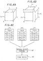
- Fig. 6 illustrates a method of drawing an object.
- Fig. 7 illustrates an example of offset draw commands and polygon draw commands in the case of a translation of an object according to a conventional method.
- Fig. 1 shows an image generation apparatus according to an embodiment of the present invention which is configured as a video game machine.
- a CPU 11 is connected to a system bus (main bus) 1.
- a cache memory 12 is connected to the CPU 11 which controls the system as a whole.
- a coordinate conversion portion 13 for performing calculations for converting the coordinates of a polygon and the like is connected to the CPU 11.
- a 32-bit CPU may be used as the CPU 11.
- a main memory 21 is also connected to the system bus 1.
- a CD-ROM decoder 31 and a DMA (direct memory access) controller 41 are connected to the system bus 1.
- a CD-ROM driver 32 is connected to the CD-ROM decoder 31.
- a CD-ROM is loaded in the CD-ROM driver 32.
- CD-ROM contains an application program including polygon draw commands and data including image data which has been compressed using, for example, discrete cosine transformation (DCT).
- DCT discrete cosine transformation
- An image decompression portion 53 is also connected to the system bus 1 through an FIFO buffer 51 and an FIFO buffer 52 at input and output ends thereof, respectively.
- the image decompression portion 53 decompresses the above-described compressed image data.
- a drawing device portion 62 is also connected to the system bus 1 through an FIFO buffer 61.
- a frame buffer 66 is connected to the drawing device portion 62.
- a D-A converter 67 is connected to the frame buffer 66.
- An image display monitor 68 is connected to the D-A converter 67.
- the drawing device portion 62 executes draw commands which have been received from the main memory 21 through the DMA controller 41 to draw an image on the frame buffer 66.
- it includes an offset register 63 for storing offset values for the coordinates of vertices included in a offset draw command to be described later and an adder 64 for adding the offset values to the coordinates of each vertices included in each draw command that forms a part of a draw command string for drawing the image.
- the frame buffer 66 is constituted by a frame buffer having areas which are switched at each vertical period. Image data output by the frame buffer 66 is converted by the D-A converter 67 into an analog video signal which is output to the image display monitor 68.
- a control pad 72 as a control input means for the video game machine is also connected to the system bus 1 through an interface 71. Also connected to the system bus 1 is a boot ROM 73 in which a program for starting up the video game machine is stored.
- draw commands are generated by the CPU 11 in the main memory 21; the draw commands are transferred to the drawing device portion 62 by the DMA controller 41; the drawing device portion 62 executes the draw commands to draw an image on the frame buffer 66; and the image is displayed on the image display monitor 66.
- the draw commands transferred from the main memory 21 to the drawing device portion 62 include offset draw commands which precede respective strings of draw commands to draw an image.
- a draw command string Aoi for the object OI is preceded by an offset draw command Ooi; a draw command string Aoj for the object OJ that follows the draw command string Aoi is preceded by an offset draw command Ooj inserted therebetween; and a draw command string Aok for the object OK that follows the draw command string Aoj is preceded by an offset draw command Ook inserted therebetween.
- a header portion of each of the offset draw commands Ooi, Ooj, and Ook includes data AD that indicates the address in the main memory 21 of the next draw command to be executed.
- the header portion of the offset draw command Ooj includes the address of the first draw command IPa in the draw command string Aoj for the object OJ.
- the header portions are followed by indication codes OFIN indicating that the subsequent data is offset draw commands which are in turn followed by offset values dx and dy for the coordinates of the vertices of the respective objects OI, OJ, and OK.
- the offset values dx and dy are generated by the CPU 11 in accordance with input operations using the control pad 72, stored in combination with the respective address data AD and indication codes OFIN in the main memory 21 as the offset draw commands Ooi, Ooj, and Ook, and transferred from the main memory 21 to the drawing device portion 62 by the DMA controller 41.
- the draw command string Aoj for the object OJ is constituted by draw commands IPa, IPb, and IPc for the divided polygons Pa, Pb, and Pc.
- the draw commands IPa, IPb, and IPc include data AD indicating the addresses in the main memory 21 of the next draw commands to be executed in header portions thereof.
- the header portions are followed by indication codes INCO indicating that the subsequent data is polygon draw commands which are in turn followed by coordinate strings for the vertices of the respective polygons Pa, Pb, and Pc.
- the draw command strings Aoi and Aok for the objects OI and OK have the same configuration except that, when the object OK is the last object drawn in a frame, the last draw command to be executed in the draw command string Aok for the object OK includes an indication code indicating that it is the last draw command in the frame instead of the address data AD, although not shown.
- certain consecutive memory areas in the main memory 21 are represented by addresses A0, A1, A2. A3. and A4.
- the offset draw command Ooj, polygon draw command IPa, polygon draw command IPc, polygon draw command IPb, and offset draw command Ook are stored in the addresses A0, A1, A2, A3, and A4, respectively.
- the address data AD of the offset draw command Ooj, polygon draw command IPa, polygon draw command IPb, and polygon draw command IPc indicate addresses A1, A3, A2. and A4, respectively.
- the DMA controller 41 transfers the offset draw commands and polygon draw commands from the main memory 21 to the drawing device portion 62 in an order which is in accordance with the addresses of those commands in the main memory 21 indicated by the respective address data AD. Specifically, in the example shown in Fig. 2, they are transferred as a list of draw command strings in an order such that the offset draw command Ooj is transferred first and is followed by the polygon draw command IPa, polygon draw command IPb, polygon draw command IPc, then offset draw command Ook.
- the offset values dx and dy for the coordinates of vertices in the offset draw command Ooj are written in the offset register 63, and the adder 64 sequentially adds the offset values dx and dy to the coordinates of the respective vertices of the polygons Pa, Pb, and Pc in the polygon draw commands IPa, IPb, and IPc to sequentially obtain the coordinates of respective vertices for translated versions of the polygons Pa, Pb, and Pc based on which the polygons Pa, Pb, and Pc are sequentially drawn on the frame buffer 66 so that the object OJ is translated on the display in the X and Y directions by the offset values dx and dy, respectively.
- the offset values dx and dy for the coordinates of vertices in the offset draw command Ooj are doubled, with the coordinates of the vertices of the polygons Pa, Pb, and Pc in the polygon draw commands IPa, IPb, and IPc kept unchanged.
- the main memory 21 can be sequentially accessed according to the address data AD to obtain the offset draw commands and polygon draw commands in a linked form in the order of execution. Accordingly, it is not necessary that the offset draw commands and polygon draw commands are placed in consecutive memory areas on the main memory in the order of execution.
- the polygons Pa, Pb, and Pc are sequentially drawn in the order listed to draw the object OJ. If these polygons are to be sequentially drawn in an order such that the polygon Pa is drawn first and is followed by the polygon Pc and then the polygon Pb, the address data AD in the polygon draw commands IPa, IPc, and IPb are rewritten to respectively indicate the addresses A2, A3, and A4 in the main memory 21.
- the above-described address data AD may be omitted as shown in Fig. 3.
- the DMA controller 41 transfers the offset draw commands and polygon draw commands from the main memory 21 to the drawing device portion 62 in accordance with the order of the addresses of those commands in the main memory 21. Therefore, to change the order of the execution of the draw commands, the positions of the draw commands in the main memory 21 must be changed.
- the present invention is not limited to 3D objects.
- the present invention may be applied to a translation of a simple polygon and a translation of an image such as a background image.
- An example of such a translation of a background image is as follows.
- one frame of a background image is constituted by 320 (rows) X 240 (columns) pixels; such a frame of image is divided into 300 macro-blocks MB as shown in Fig. 4 each constituted by 16 (rows) X 16 (columns) pixels; and the background image is drawn on a macro-block basis.
- a draw command for this background image includes a header portion containing data AD indicating the address in the main memory 21 of the next draw command to be executed, an indication code INCO indicating that the subsequent data is draw commands for the background image, data H and W indicating the height and width of a macro-block area MA in which the background image is to be drawn, data X and Y indicating the coordinates of the upper left vertex of the macro-block area MA, and image data IP which follows the header portion.
- the width of the macro-block area MA corresponds to the width of one macro-block MB
- the height of the macro-block area MA corresponds to the height of one macro-block or a plurality of macro-blocks which are consecutive in the vertical direction.
- the image data IP has been decompressed by the image decompression portion 53.
- Such a background image may be treated similarly to a polygon, so it can be translated on the display screen using the above-described method.
- the coordinate conversion portion 13 may be connected to the system bus 1 instead of being pipeline-connected to the CPU as in the illustrated embodiment.
- Application programs and data may be recorded using in semiconductor memories such as magnetic discs and memory cards instead of CD-ROMs.
Landscapes
- Physics & Mathematics (AREA)
- General Physics & Mathematics (AREA)
- Engineering & Computer Science (AREA)
- Theoretical Computer Science (AREA)
- Image Generation (AREA)
- Ultra Sonic Daignosis Equipment (AREA)
- Controls And Circuits For Display Device (AREA)
- Closed-Circuit Television Systems (AREA)
- Processing Or Creating Images (AREA)
- Endoscopes (AREA)
- Apparatus For Radiation Diagnosis (AREA)
Claims (6)
- Bilderzeugungsvorrichtung mit:dadurch gekennzeichnet, dasseinem Vollbildpuffer (66), in dem ein Bild gezeichnet wird;einer CPU (11) zum Erzeugen eines Versatzzeichnungsbefehls, der Versatzwerte für die Koordinaten der Ecken eines Bilds anzeigt, sowie einer Kette von Zeichnungsbefehlen zum Zeichnen des Bilds;einem Hauptspeicher (21), in dem der Versatzzeichnungsbefehl und die Kette von Zeichnungsbefehlen, wie von der CPU (11) erzeugt, gespeichert werden; undeinem Zeichnungseinrichtungsabschnitt (62) zum Ausführen des Versatzzeichnungsbefehls vor der Kette von Befehlen, wie vom Hauptspeicher (21) geliefert, um ein verschobenes Bild im Vollbildpuffer (66) zu zeichnen;der Zeichnungseinrichtungsabschnitt (62) eine Versatzregistereinrichtung (63) zum Einspeichern von Versatzwerten sowie eine Addierereinrichtung (64) zum Addieren der Versatzwerten zu den Koordinaten der jeweiligen Ecken in jedem Zeichnungsbefehl beinhaltet.
- Vorrichtung nach Anspruch 1, bei der die Zeichnungsbefehle Polygone und Zeichnungsbefehle als kleinste Einheiten zum Zeichnen einer Figur beinhalten, und bei der der Addierer (64) so ausgebildet ist, dass er für jedes der Polygone den Versatzbefehl zum Zeichnungsbefehl addiert.
- Vorrichtung nach Anspruch 2, ferner mit einer Einrichtung zum Einschließen eines Hinweiscodes, der anzeigt, dass die Daten einen Polygonzeichnungsbefehl bilden, in jeden Zeichnungsbefehl.
- Vorrichtung nach Anspruch 3, ferner mit einer Einrichtung zum Einschließen eines Hinweiscodes, der anzeigt, dass die Daten Versatzdaten sind, und Daten, die das Ausmaß des Versatzes anzeigen, in jeden Versatzbefehl.
- Vorrichtung nach Anspruch 4, ferner mit einer Einrichtung zum Verschieben des Polygons entsprechend ersten und zweiten Daten, die den Versatz repräsentieren.
- Vorrichtung nach Anspruch 5, ferner mit einer Steuerungseingabeeinrichtung (72), wobei der Versatzzeichnungsbefehl entsprechend Eingabeoperationen unter Verwendung der Steuerungseingabeeinrichtung erzeugt wird.
Applications Claiming Priority (3)
| Application Number | Priority Date | Filing Date | Title |
|---|---|---|---|
| JP9571794 | 1994-04-08 | ||
| JP6095717A JPH07282270A (ja) | 1994-04-08 | 1994-04-08 | 画像生成方法および装置 |
| JP95717/94 | 1994-04-08 |
Publications (3)
| Publication Number | Publication Date |
|---|---|
| EP0676719A2 EP0676719A2 (de) | 1995-10-11 |
| EP0676719A3 EP0676719A3 (de) | 1997-06-04 |
| EP0676719B1 true EP0676719B1 (de) | 2000-02-23 |
Family
ID=14145238
Family Applications (1)
| Application Number | Title | Priority Date | Filing Date |
|---|---|---|---|
| EP95105312A Expired - Lifetime EP0676719B1 (de) | 1994-04-08 | 1995-04-07 | Vorrichtung zur Darstellung von Bildern |
Country Status (9)
| Country | Link |
|---|---|
| US (1) | US5943061A (de) |
| EP (1) | EP0676719B1 (de) |
| JP (1) | JPH07282270A (de) |
| KR (1) | KR100371253B1 (de) |
| CN (1) | CN1105966C (de) |
| AT (1) | ATE189934T1 (de) |
| CA (1) | CA2146518C (de) |
| DE (1) | DE69515137T2 (de) |
| ES (1) | ES2142421T3 (de) |
Cited By (2)
| Publication number | Priority date | Publication date | Assignee | Title |
|---|---|---|---|---|
| US6383079B1 (en) | 1995-11-22 | 2002-05-07 | Nintendo Co., Ltd. | High performance/low cost video game system with multi-functional peripheral processing subsystem |
| US6394905B1 (en) | 1995-11-22 | 2002-05-28 | Nintendo Co., Ltd. | Systems and methods for providing security in a video game system |
Families Citing this family (7)
| Publication number | Priority date | Publication date | Assignee | Title |
|---|---|---|---|---|
| US6331856B1 (en) | 1995-11-22 | 2001-12-18 | Nintendo Co., Ltd. | Video game system with coprocessor providing high speed efficient 3D graphics and digital audio signal processing |
| JP2001283254A (ja) | 2000-03-31 | 2001-10-12 | Mitsubishi Electric Corp | 3次元グラフィックス描画装置およびその方法 |
| JP4603902B2 (ja) * | 2005-02-16 | 2010-12-22 | 株式会社メガチップス | 3dグラフィック表示システムおよび表示装置並びに電子メッセージ転送システムおよび表示装置 |
| US20100020088A1 (en) * | 2007-02-28 | 2010-01-28 | Panasonic Corporation | Graphics rendering device and graphics rendering method |
| JP2008249977A (ja) * | 2007-03-30 | 2008-10-16 | Seiko Epson Corp | 電気光学表示装置の描画回路、電気光学表示装置の描画方法、電気光学表示装置及び電子機器 |
| CN117292039B (zh) * | 2023-11-27 | 2024-02-13 | 芯瞳半导体技术(山东)有限公司 | 顶点坐标生成方法、装置、电子设备及计算机存储介质 |
| CN117744187B (zh) * | 2024-02-20 | 2024-05-14 | 广州中望龙腾软件股份有限公司 | Cad绘图方法、装置、计算机设备和存储介质 |
Family Cites Families (13)
| Publication number | Priority date | Publication date | Assignee | Title |
|---|---|---|---|---|
| JP2728411B2 (ja) * | 1987-12-16 | 1998-03-18 | 株式会社日立製作所 | 図形データ表示方法及び装置 |
| US5265198A (en) * | 1989-10-23 | 1993-11-23 | International Business Machines Corporation | Method and processor for drawing `polygon with edge`-type primitives in a computer graphics display system |
| EP0430501B1 (de) * | 1989-11-17 | 1999-02-03 | Digital Equipment Corporation | System und Verfahren zum unverfälschten Polygonenzeichnen |
| KR930007023B1 (ko) * | 1990-12-31 | 1993-07-26 | 삼성전자 주식회사 | 컴퓨터 그래픽 시스템에서의 화상변환방법 및 그 장치 |
| US5321810A (en) * | 1991-08-21 | 1994-06-14 | Digital Equipment Corporation | Address method for computer graphics system |
| JPH05190763A (ja) | 1992-01-14 | 1993-07-30 | Murata Mfg Co Ltd | 封止部品 |
| JPH05190764A (ja) | 1992-01-17 | 1993-07-30 | Hitachi Ltd | 半導体装置 |
| JPH05258625A (ja) | 1992-03-13 | 1993-10-08 | Sumitomo Metal Ind Ltd | 超伝導線材の製造方法 |
| US5483627A (en) * | 1992-04-29 | 1996-01-09 | Canon Kabushiki Kaisha | Preprocessing pipeline for real-time object based graphics systems |
| JP3078655B2 (ja) | 1992-07-09 | 2000-08-21 | 富士通株式会社 | 光ビーム走査装置 |
| US5596693A (en) * | 1992-11-02 | 1997-01-21 | The 3Do Company | Method for controlling a spryte rendering processor |
| JP3492761B2 (ja) * | 1994-04-07 | 2004-02-03 | 株式会社ソニー・コンピュータエンタテインメント | 画像生成方法及び装置 |
| US5664162A (en) * | 1994-05-23 | 1997-09-02 | Cirrus Logic, Inc. | Graphics accelerator with dual memory controllers |
-
1994
- 1994-04-08 JP JP6095717A patent/JPH07282270A/ja active Pending
-
1995
- 1995-04-06 CA CA002146518A patent/CA2146518C/en not_active Expired - Fee Related
- 1995-04-07 KR KR1019950008015A patent/KR100371253B1/ko not_active Expired - Lifetime
- 1995-04-07 EP EP95105312A patent/EP0676719B1/de not_active Expired - Lifetime
- 1995-04-07 ES ES95105312T patent/ES2142421T3/es not_active Expired - Lifetime
- 1995-04-07 AT AT95105312T patent/ATE189934T1/de active
- 1995-04-07 DE DE69515137T patent/DE69515137T2/de not_active Expired - Lifetime
- 1995-04-08 CN CN95104022A patent/CN1105966C/zh not_active Expired - Fee Related
-
1996
- 1996-09-05 US US08/708,883 patent/US5943061A/en not_active Expired - Lifetime
Cited By (2)
| Publication number | Priority date | Publication date | Assignee | Title |
|---|---|---|---|---|
| US6383079B1 (en) | 1995-11-22 | 2002-05-07 | Nintendo Co., Ltd. | High performance/low cost video game system with multi-functional peripheral processing subsystem |
| US6394905B1 (en) | 1995-11-22 | 2002-05-28 | Nintendo Co., Ltd. | Systems and methods for providing security in a video game system |
Also Published As
| Publication number | Publication date |
|---|---|
| JPH07282270A (ja) | 1995-10-27 |
| CA2146518C (en) | 2006-03-21 |
| CA2146518A1 (en) | 1995-10-09 |
| ES2142421T3 (es) | 2000-04-16 |
| DE69515137D1 (de) | 2000-03-30 |
| EP0676719A2 (de) | 1995-10-11 |
| KR100371253B1 (ko) | 2003-03-31 |
| CN1123928A (zh) | 1996-06-05 |
| US5943061A (en) | 1999-08-24 |
| EP0676719A3 (de) | 1997-06-04 |
| ATE189934T1 (de) | 2000-03-15 |
| CN1105966C (zh) | 2003-04-16 |
| KR950033961A (ko) | 1995-12-26 |
| DE69515137T2 (de) | 2000-08-31 |
Similar Documents
| Publication | Publication Date | Title |
|---|---|---|
| JP3492761B2 (ja) | 画像生成方法及び装置 | |
| JP3647487B2 (ja) | テクスチャマッピング装置 | |
| EP0820037B1 (de) | Apparat und verfahren zum zeichnen | |
| KR100380705B1 (ko) | 화상생성방법및장치와,게임재생장치 | |
| US7170512B2 (en) | Index processor | |
| US5917504A (en) | Image processing apparatus, switching between images having pixels of first and second numbers of bits | |
| EP0676719B1 (de) | Vorrichtung zur Darstellung von Bildern | |
| US5659672A (en) | Method and apparatus for generating images | |
| JP3586991B2 (ja) | テクスチャ・データ読出装置およびレンダリング装置 | |
| US6392643B1 (en) | Image generation apparatus | |
| US6950108B2 (en) | Bandwidth reduction for rendering using vertex data | |
| US20100164965A1 (en) | Rendering module for bidimensional graphics, preferably based on primitives of active edge type | |
| JP3468985B2 (ja) | グラフィック描画装置、グラフィック描画方法 | |
| JP2003150975A (ja) | 画像生成装置 | |
| JPH11224331A (ja) | ラスタ画像生成装置およびラスタ画像生成方法 | |
| JPH0773333A (ja) | 画像生成方法及び装置 | |
| JPH103466A (ja) | 中央演算処理装置およびこれを用いた画像生成装置 | |
| JPH10222695A (ja) | 描画装置および描画方法 | |
| JPH0765177A (ja) | 画像処理システムおよび画像処理装置 | |
| JPH0744730A (ja) | 画像変換処理方法 | |
| JP2000242792A (ja) | 画像処理装置及び方法、並びに画像処理プログラムを供給するプログラム供給媒体 | |
| JPH02118889A (ja) | 文字図形塗り潰し回路 | |
| JPH08202882A (ja) | 出力装置および出力方法 | |
| JPH06168095A (ja) | 画像表示装置 |
Legal Events
| Date | Code | Title | Description |
|---|---|---|---|
| PUAI | Public reference made under article 153(3) epc to a published international application that has entered the european phase |
Free format text: ORIGINAL CODE: 0009012 |
|
| AK | Designated contracting states |
Kind code of ref document: A2 Designated state(s): AT DE ES FR GB NL |
|
| PUAL | Search report despatched |
Free format text: ORIGINAL CODE: 0009013 |
|
| RHK1 | Main classification (correction) |
Ipc: G06T 3/20 |
|
| AK | Designated contracting states |
Kind code of ref document: A3 Designated state(s): AT DE ES FR GB NL |
|
| 17P | Request for examination filed |
Effective date: 19971105 |
|
| 17Q | First examination report despatched |
Effective date: 19980402 |
|
| GRAG | Despatch of communication of intention to grant |
Free format text: ORIGINAL CODE: EPIDOS AGRA |
|
| GRAG | Despatch of communication of intention to grant |
Free format text: ORIGINAL CODE: EPIDOS AGRA |
|
| GRAG | Despatch of communication of intention to grant |
Free format text: ORIGINAL CODE: EPIDOS AGRA |
|
| GRAH | Despatch of communication of intention to grant a patent |
Free format text: ORIGINAL CODE: EPIDOS IGRA |
|
| GRAH | Despatch of communication of intention to grant a patent |
Free format text: ORIGINAL CODE: EPIDOS IGRA |
|
| GRAA | (expected) grant |
Free format text: ORIGINAL CODE: 0009210 |
|
| AK | Designated contracting states |
Kind code of ref document: B1 Designated state(s): AT DE ES FR GB NL |
|
| REF | Corresponds to: |
Ref document number: 189934 Country of ref document: AT Date of ref document: 20000315 Kind code of ref document: T |
|
| REF | Corresponds to: |
Ref document number: 69515137 Country of ref document: DE Date of ref document: 20000330 |
|
| REG | Reference to a national code |
Ref country code: ES Ref legal event code: FG2A Ref document number: 2142421 Country of ref document: ES Kind code of ref document: T3 |
|
| ET | Fr: translation filed | ||
| RAP2 | Party data changed (patent owner data changed or rights of a patent transferred) |
Owner name: SONY COMPUTER ENTERTAINMENT INC. |
|
| PLBE | No opposition filed within time limit |
Free format text: ORIGINAL CODE: 0009261 |
|
| STAA | Information on the status of an ep patent application or granted ep patent |
Free format text: STATUS: NO OPPOSITION FILED WITHIN TIME LIMIT |
|
| NLT2 | Nl: modifications (of names), taken from the european patent patent bulletin |
Owner name: SONY COMPUTER ENTERTAINMENT INC. |
|
| 26N | No opposition filed | ||
| REG | Reference to a national code |
Ref country code: GB Ref legal event code: IF02 |
|
| PGFP | Annual fee paid to national office [announced via postgrant information from national office to epo] |
Ref country code: DE Payment date: 20120419 Year of fee payment: 18 Ref country code: NL Payment date: 20120425 Year of fee payment: 18 |
|
| PGFP | Annual fee paid to national office [announced via postgrant information from national office to epo] |
Ref country code: FR Payment date: 20120504 Year of fee payment: 18 Ref country code: GB Payment date: 20120404 Year of fee payment: 18 |
|
| PGFP | Annual fee paid to national office [announced via postgrant information from national office to epo] |
Ref country code: ES Payment date: 20120424 Year of fee payment: 18 |
|
| PGFP | Annual fee paid to national office [announced via postgrant information from national office to epo] |
Ref country code: AT Payment date: 20120327 Year of fee payment: 18 |
|
| REG | Reference to a national code |
Ref country code: NL Ref legal event code: V1 Effective date: 20131101 |
|
| REG | Reference to a national code |
Ref country code: AT Ref legal event code: MM01 Ref document number: 189934 Country of ref document: AT Kind code of ref document: T Effective date: 20130430 |
|
| GBPC | Gb: european patent ceased through non-payment of renewal fee |
Effective date: 20130407 |
|
| PG25 | Lapsed in a contracting state [announced via postgrant information from national office to epo] |
Ref country code: DE Free format text: LAPSE BECAUSE OF NON-PAYMENT OF DUE FEES Effective date: 20131101 Ref country code: GB Free format text: LAPSE BECAUSE OF NON-PAYMENT OF DUE FEES Effective date: 20130407 Ref country code: AT Free format text: LAPSE BECAUSE OF NON-PAYMENT OF DUE FEES Effective date: 20130430 |
|
| REG | Reference to a national code |
Ref country code: FR Ref legal event code: ST Effective date: 20131231 |
|
| REG | Reference to a national code |
Ref country code: DE Ref legal event code: R119 Ref document number: 69515137 Country of ref document: DE Effective date: 20131101 |
|
| PG25 | Lapsed in a contracting state [announced via postgrant information from national office to epo] |
Ref country code: FR Free format text: LAPSE BECAUSE OF NON-PAYMENT OF DUE FEES Effective date: 20130430 Ref country code: NL Free format text: LAPSE BECAUSE OF NON-PAYMENT OF DUE FEES Effective date: 20131101 |
|
| REG | Reference to a national code |
Ref country code: ES Ref legal event code: FD2A Effective date: 20140609 |
|
| PG25 | Lapsed in a contracting state [announced via postgrant information from national office to epo] |
Ref country code: ES Free format text: LAPSE BECAUSE OF NON-PAYMENT OF DUE FEES Effective date: 20130408 |