EP0677369A1 - Procede de moulage par injection empechant la formation de defauts superficiels, et moules metalliques utilises pour le moulage par injection - Google Patents
Procede de moulage par injection empechant la formation de defauts superficiels, et moules metalliques utilises pour le moulage par injection Download PDFInfo
- Publication number
- EP0677369A1 EP0677369A1 EP94903015A EP94903015A EP0677369A1 EP 0677369 A1 EP0677369 A1 EP 0677369A1 EP 94903015 A EP94903015 A EP 94903015A EP 94903015 A EP94903015 A EP 94903015A EP 0677369 A1 EP0677369 A1 EP 0677369A1
- Authority
- EP
- European Patent Office
- Prior art keywords
- mold
- heat insulating
- insulating film
- resin
- film
- Prior art date
- Legal status (The legal status is an assumption and is not a legal conclusion. Google has not performed a legal analysis and makes no representation as to the accuracy of the status listed.)
- Withdrawn
Links
Images


Classifications
-
- B—PERFORMING OPERATIONS; TRANSPORTING
- B29—WORKING OF PLASTICS; WORKING OF SUBSTANCES IN A PLASTIC STATE IN GENERAL
- B29C—SHAPING OR JOINING OF PLASTICS; SHAPING OF MATERIAL IN A PLASTIC STATE, NOT OTHERWISE PROVIDED FOR; AFTER-TREATMENT OF THE SHAPED PRODUCTS, e.g. REPAIRING
- B29C45/00—Injection moulding, i.e. forcing the required volume of moulding material through a nozzle into a closed mould; Apparatus therefor
- B29C45/17—Component parts, details or accessories; Auxiliary operations
- B29C45/26—Moulds
-
- B—PERFORMING OPERATIONS; TRANSPORTING
- B29—WORKING OF PLASTICS; WORKING OF SUBSTANCES IN A PLASTIC STATE IN GENERAL
- B29C—SHAPING OR JOINING OF PLASTICS; SHAPING OF MATERIAL IN A PLASTIC STATE, NOT OTHERWISE PROVIDED FOR; AFTER-TREATMENT OF THE SHAPED PRODUCTS, e.g. REPAIRING
- B29C45/00—Injection moulding, i.e. forcing the required volume of moulding material through a nozzle into a closed mould; Apparatus therefor
- B29C45/0025—Preventing defects on the moulded article, e.g. weld lines, shrinkage marks
-
- B—PERFORMING OPERATIONS; TRANSPORTING
- B29—WORKING OF PLASTICS; WORKING OF SUBSTANCES IN A PLASTIC STATE IN GENERAL
- B29C—SHAPING OR JOINING OF PLASTICS; SHAPING OF MATERIAL IN A PLASTIC STATE, NOT OTHERWISE PROVIDED FOR; AFTER-TREATMENT OF THE SHAPED PRODUCTS, e.g. REPAIRING
- B29C45/00—Injection moulding, i.e. forcing the required volume of moulding material through a nozzle into a closed mould; Apparatus therefor
- B29C45/17—Component parts, details or accessories; Auxiliary operations
- B29C45/26—Moulds
- B29C45/37—Mould cavity walls, i.e. the inner surface forming the mould cavity, e.g. linings
-
- B—PERFORMING OPERATIONS; TRANSPORTING
- B29—WORKING OF PLASTICS; WORKING OF SUBSTANCES IN A PLASTIC STATE IN GENERAL
- B29C—SHAPING OR JOINING OF PLASTICS; SHAPING OF MATERIAL IN A PLASTIC STATE, NOT OTHERWISE PROVIDED FOR; AFTER-TREATMENT OF THE SHAPED PRODUCTS, e.g. REPAIRING
- B29C45/00—Injection moulding, i.e. forcing the required volume of moulding material through a nozzle into a closed mould; Apparatus therefor
- B29C45/17—Component parts, details or accessories; Auxiliary operations
- B29C45/26—Moulds
- B29C45/2628—Moulds with mould parts forming holes in or through the moulded article, e.g. for bearing cages
Definitions
- the present invention relates to an injection molding method for manufacturing a product having a front surface free from defects such as sink marks or weld lines.
- the present invention is also directed to a mold assembly suitable for manufacturing such a product.
- thermoplastic resin According to a method of injection molding a thermoplastic resin, the product which even has a complicated profile can be easily manufactured with high productivity.
- the injection molding process has been adopted in various field, e.g. for manufacturing industrial parts or living necessaries.
- a molten resin to be injection molded is forcibly poured through a gate into a molding cavity defined in a mold assembly.
- the poured resin passes through a predetermined channel to fill the cavity.
- the resin is diverged to a plurality of flows and then joined together during the fluidization in the cavity.
- the incomplete joining causes the formation of weld lines.
- a plurality of gates are opened to the molding cavity. Consequently, weld lines are formed on the surface of the product with high frequency.
- the molten resin poured in the molding cavity is cooled and solidified in the state to fill the cavity.
- the resin reduces its volume due to phase transformation or thermal shrinkage during the cooling and solidification.
- the volumetric shrinkage is not uniformly promoted in the resin body, but is likely to concentrate at a certain part.
- the uneven shrinkage causes the formation of defects such as sink marks on the surface of an obtained product.
- the resin especially at the thick wall part, where cooling and solidification would be delayed due to mass effect, is held in a highly fluid state, although the resin at the surroundings has been already solidified. Consequently, a stress originated in the shrinkage of the resin at the surroundings is accumulated in the resin at the thick wall part, so that sink marks are concentratedly formed on both the surfaces of the thick wall part.
- Such a thick wall part is effective in an obtained product, e.g. as a reinforcing rib or a boss for fixture maldistributed on the periphery or interior of the product, or an outer or inner frame.
- surface defects such as sink marks or weld lines formed at the thick wall part or its neighborhood remarkably reduces the commercial value of the product.
- the sink marks becomes deeper as the thickness of the rib, the larger diameter of the boss or the higher temperature of the molten resin.
- the fountain flow 21 from which the molten resin 20 continuously gushes out is formed at the top end of the molten resin 20 passing into the cavity 13.
- the resin 20 is rapidly cooled and solidified by thermal diffusion through the molds 11, 12, to form a skin layer 23 in contact with the inner surface of each mold 11, 12.
- the cooling and solidification of the resin 20 is interpreted from the movement of the resin flow unit 22 as such that the resin 20 is stretched longer near the inner surface of each mold 11, 12 and formed to the skin layer 23 orientated due to the stretching.
- the molten resin 20 stops its fluidization.
- the interior of the molten resin 20 in the stationary state is cooled through the molds 11, 12, so that the skin layer 23 grows up to a thick solidified layer along the direction from the inner surface of each mold 11, 12 to the interior of the resin 20.
- the molten resin 20 reduces its volume. Consequently, the interior of the molten resin 20 becomes at a negative pressure.
- skin layer in the following explanation means one involving said solidified layer.
- the cooling and solidification of the molten resin 20 at the thick wall part is delayed in comparison with the cooling and solidification of the molten resin 20 at the surroundings. Due to said delay, the shrinkage strain of the molten resin 20 at the surroundings is accumulated in the thick wall part, so that a fairly large negative pressure is formed at the thick wall part. Said negative pressure affects on the skin layer 23, which is still viscous, at the thick wall part. Either of the skin layers 23, which is softer or less adhesive to the inner surface of the mold 11 or 12, is peeled off the inner surface. As a result, the surface of the solidified resin body is depressed. Hereby, sink marks are formed on the surface of an obtained resin product.
- An injection molded product is ordinarily used with its flat surface faced to a user.
- a skin layer 23 for forming the flat surface shrinks along the inner surface of a mold during cooling and solidification, so that the skin layer 23 is easily peeled off the inner surface.
- a skin layer 23 for forming the back side of the product is hardly peeled off the inner surface of the mold, since the back side has a complicated profile due to the formation of ribs and/or bosses.
- the skin layers for forming the front and back surfaces exhibit adhesiveness different from each other to the inner surfaces of the molds. Due to said difference in adhesiveness, the skin layer for forming the front surface is preferentially pulled inwards by the negative pressure in the interior of the molten resin. Thus, sink marks are formed on the front surface of the product.
- a molten resin is injected into a molding cavity in an amount insufficient to completely fill the cavity, and a high-pressure gas is forcibly injected into the cavity so as to form a hollow portion in the molten resin.
- the high-pressure gas may be simultaneously injected into the cavity with the molten resin.
- the injected molten resin is dwelled by the application of the gaseous high pressure through the hollow resin passage.
- the resin is cooled and solidified in a state pressed onto the inner surface of the mold.
- a thick wall part communicating with a gas passage.
- said thick wall part acts as a flow leader for the molten resin, so as to destroy the injection balance of the resin with respect to the whole body of the product.
- surface defects such as air traps and flow marks are easily formed on the surface of the obtained product.
- the short-shot process necessarily uses the high -pressure gas.
- the use of the high-pressure gas requires dangerous operations, difficult handling and a special expensive control system. Due to these defects, the short-shot process has not been developed to broad extents.
- Japanese Patent Application Laid-Open 56-167410 teaches a local heating method, wherein the back side of a mold is partially heated at a position easy to form sink marks. A molten resin in contact with the heated mold part is delayed in cooling and solidification from the other part. When the back side at the position easy to form sink marks is partially heated at a temperature higher than that of the mold, sink marks are formed on the back side of the product hut not on its front surface. Hereby, the obtained product does not substantially reduce its commercial value due to the sink marks.
- the local heating of the mold causes the elongation of an injection molding cycle and additionally requires heating means.
- Japanese Patent Application Laid-Open 61-9126 teaches the provision of a porous nozzle at the part of the back side easy to form sink marks. Compressed air is introduced through the porous nozzle into the cavity so as to press the back side of aresin body. The resin is cooled and solidified in the state tightly pressed onto the inner surface of the mold by the application of the compressed air. Hereby, an obtained product has a smooth surface without the formation of sink marks.
- the method requires a specially designed mold in which the nozzle made of a porous material can be installed.
- the injection of the compressed air through the porous nozzle requires additional equipment and put restrictions on the structure of the mold.
- a molten resin poured into a molding cavity is diverged to a plurality of flows and then joined in response to the configulation of said cavity.
- a plurality of the resin flows are joined together, their skin layers are fused to each other. If the skin layers are fixed without sufficient fusion, a weld line is formed at the joining position. The weld line reduces the commercial value of a product, too.
- heating and cooling means are provided at the parts of a mold easy to form weld lines, as disclosed in Japanese Patent Application Laid-Open 51-22759.
- the fusion of the skin layers to each other can be promoted by the application of a shearing force to a part of a molten resin in the cavity, as disclosed in Japanese Patent Application Laid-Open 3-274127.
- Said fusion may be promoted by the transmission of ultrasonic waves to a molten resin in a fluid state, as disclosed in Japanese Patent Application Laid-Open 4-90309.
- Japanese Patent Application Laid-Open 4-211912 discloses the injection mold which can simultaneously inhibit the formation of weld lines and flow marks.
- Said mold has an inner surface coated with a heat insulating layer.
- the layer has thickness of 0.5-50 ⁇ m, heat conductivity of 0.1cal/cm ⁇ sec ⁇ °C or less and an angle of contact with water not more than 30 degrees.
- the layer is made of a material such as metallic oxide, silicic oxide, silicic complex oxide and plasma-polymerized plastics.
- the layer When a molten resin injected into the molding cavity comes in contact with the heat insulating layer, the layer is instantaneously heated at a high temperature by a heat retained in the molten resin.
- the heated layer exhibits excellent wettability and conformability to the molten resin, so as to improve the transferring ability of the mold. Consequently, a product having the profile which accurately imitates the configulation of the molding cavity is obtained without the formation of weld lines or flow marks.
- the mold having the inner surface ocated with the heat insulating layer does not have the effect to inhibit the formation of sink marks originated in the volumetric shrinkage of the molten resin during cooling and solidification.
- a molten resin injected into the molding cavity is rapidly cooled, just after it comes in contact with the inner surface of the mold.
- a surfacial skin layer is formed on the surface part of the molten resin in contact with the inner surface of the mold.
- the cooling and solidification of the molten resin 20 continues while gradually thickening the surfacial skin layer inwards to the skin layer 23.
- a negative pressure is formed in the interior of the molten resin 20 by the abrupt volumetric shrinkage which occurs at a glass-transition temperature.
- the negative pressure acts as the power to pull the skin layer 23 inwards shown by the arrows in Fig. 2, and becomes larger with the cooling and solidification of the molten resin 20.
- the skin layer 23 is peeled off the inner surface of the mold and pulled inwards.
- the resulting dent acts as a starting point for the formation of sink marks.
- An object of the present invention is to adversely utilize the dent-forming phenomenon to obtain an injection molded product excellent in surface appearance.
- Another object of the present invention is to provide a simplified method capable of inhibiting the formation of sink marks on the front surface of a product with ease, as well as the formation of weld lines caused by the joining of resin flows during the injection of a molten resin into a molding cavity.
- an injection mold assembly comprising a stationary mold and a movable mold.
- the inner surface of either the stationary mold or the movable mold, corresponding to the front surface of a product, is coated with a heat insulating film excellent in wettability and conformability to a molten resin to be injected.
- the mold having the inner surface coated with said heat insulating film is clamped together with the other mold to define a molding cavity.
- a molten thermoplastic resin in a predetermined amount is injected into the cavity.
- the growth of a skin layer as well as the peeling of the skin layer are delayed near the inner surface of the mold coated with the heat insulating film.
- the molten resin is ordinarily cooled and solidified near the inner surface of the other mold uncoated with the heat insulating film, so that the skin layer is preferentially peeled off the inner surface early in the progress of the volumetric shrinkage of the resin.
- the preferential peeling of the skin layer absorbs the volumetric shrinkage of the resin being cooled and solidified, at the side of the other mold uncoated with the heat insulating film.
- the front surface of the product is prevented from the formation of defects such as sink marks.
- the heat insulating film formed on the inner surface of the mold exhibits a instantaneous heat insulating effect, when the molten resin is injected into the molding cavity. Owing to the heat insulating effect, a skin layer formed in contact with the inner surface of the mold is remelted by a heat retained in the molten resin. The remelting effectively eliminates weld lines. In addition, the heat insulating film does not have any harmful influences, e.g. the elongation of molding cycle, owing to its small heat capacity.
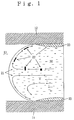
- Fig. 1 is a schematic view illustrating the top end of a molten resin flowing in a molding cavity.
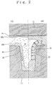
- Fig. 2 is a view for explaining the preferential formation of sink marks in the mold asembly wherein a heat insulating film is applied to the inner surface of one mold.
- Fig. 3 is the perspective view of a product obtained in Example 1.
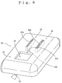
- Fig. 4 is the perspective view of a product obtained in Example 4.
- Fig. 5 is the perspective view of a product obtained in Example 6.
- molds 11 and 12 defines a molding cavity 13 corresponding to the profile of a product.
- the inner surface of the mold 11 for forming the front surface of the product is coated with a heat insulating film 14 excellent in conformability to a molten resin 20, as compared with the inner surface of the other mold 12.
- a heat insulating film 14 excellent in conformability to a molten resin 20, as compared with the inner surface of the other mold 12.
- skin layers 23a and 23b formed on the surfaces of the molten resin 20 in contact with the molds 11 and 12, respectively exhibits adhesiveness different from each other to the inner surfaces of the molds 11, 12. The difference in said adhesiveness is effectively utilized for the inhibition of sink marks.
- the injected molten resin 20 fills the molding cavity 13 between the molds 11, 12, while continuously forming a fountain flow 21 as shown in Fig. 1.
- the fountain flow 21 has the flow velocity V which becomes higher toward the center of the flow 21, as shown by the distribution of the velocity in Fig. 1.
- the molten resin 20 changes its flow direction toward the inner surface of the molds 11, 12. Due to said fluidization, the molten resin 20 is cooled and solidified in the orientated state that the molten resin 20 is elongated along the inner surfaces of the molds 11, 12.
- the skin layers 23a, 23b are formed in contact with the inner surfaces of the molds 11, 12, respectively.
- the skin layer 23a formed in contact with the inner surface of the mold 11 coated with the heat insulating film 14 is prevented from cooling, until the heat insulating film 14 is saturated with a heat.
- the skin layer 23a is instantaneously remelted by a heat transmitted from the interior of the molten resin 20, so as to relax the orientation of the resin formed during the fluidization.
- the heat insulating layer 14 suppresses the inward growth of the skin layer 23a.
- a stress along a direction perpendicular to the inner surface of the mold 11 is not formed by the volumetric shrinkage of the resin 20, so that the skin layer 23a is not affected by the shearing force which would breaks the adhesion of the skin layer 23a to the inner surface of the mold 11.
- the skin layer 23a then gradually becomes thicker.
- the orientation of the resin 20 is already relaxed, so that the volumetric shrinkage of the resin selective along a certain direction would not be formed in response to the growth of the skin layer 23a.
- there is reduced the shearing force which unfavourably affects on the adhesiveness of the skin layer 23a to the inner surface of the mold 11. Consequently, the skin layer 23a grows inwards while maintaining the excellent adhesiveness to the inner surface of the mold 11.
- the diffusion of a heat from the molten resin 20 through the mold 12 begins at the same time when the injected molten resin 20 stops fluidization.
- the molten resin 20 is rapidly cooled, so that the skin layer 23b becomes thicker on the earlier stage as compared with the skin layer 23a.
- the skin layer 23b exhibits lower adhesiveness to the inner surface of the mold 12, since the inner surface is not coated with the film 14.
- a large volumetric shrinkage i.e. a large negative pressure, is formed in the vicinity of the inner surface of the mold 12 with the growth of the skin layer 23b.
- the skin layer 23b is easily peeled off the inner surface of the mold 12 by the negative pressure, so as to form a split space 24 between the skin layer 23b and the inner surface of the mold 12, as shown in Fig. 2 (A).
- the split space 24 becomes larger, as shown in Fig. 2(B) compensating for the volumetric shrinkage of the molten resin 20 in response to its cooling and solidification.
- the skin layer 23b is partially depressed at the part, e.g. near the corner of the mold 12, where the negative pressure is concentrately applied.
- the cooling and solidification of the molten resin 20 in contact with the inner surface of the mold 11 is made different from that of the molten resin 20 in contact with the inner surface of the other mold 12, by the application of the heat insulating film 14 to the inner surface of the mold 11 for defining the front surface of a product, as afore-mentioned.
- sink marks and other faults derived from the volumetric shrinkage of the molten resin 20 are preferentially formed at the side of the mold 12.
- the skin layer 23a at the side of the mold 11 grows thicker inwards while maintaining the excellent adhesiveness to the inner surface of the mold 11. Consequently, an obtained product has a front surface excellent in smoothness because of the accumulation of sink marks in the back side, even if thick wall parts such as ribs and/or bosses are formed at the back side of said product.
- the heat insulating film 14 has the effect to eliminate weld lines, too.
- the skin layer which was solidified in the orientated state due to the elongation in contact with the inner surface of the mold 11, is remelted by a heat retained in the molten resin 20, until the heat insulating film 14 is thermally saturated.
- the remelting eliminates the weld lines, which is caused by the solidification of the skin layers in the folded state as such, at the side of the mold 11 only.
- An ordinary injection mold assembly has a molding cavity, corresponding to the profile of a product, between a movable mold and a stationary mold.
- the heat insulating film 14 excellent in wettability and conformability to a molten resin may be formed partially or wholly on the inner surface of either the movable mold or the stationary mold.
- the thickness of the film 14 may be adjusted in response to the intensiveness to form sink marks.
- a protective film or a denatured surface layer may be formed partially or wholly on the inner surface of the other mold, as far as the heat insulating film 14 formed on the inner surface of the mold for defining the front surface of a product has conformability and a heat insulating power superior to those of said protective film or denatured surface layer.
- the heat insulating film 14 necessarily has the specified heat insulating power to obtain a preferable heat insulating effect taking into consideration a molding cycle.
- the heat insulating power may be represented by the coefficient of a quantity of heat transmission, i.e. the value K/R wherein K is the thermal conductivity (cal/cm ⁇ sec ⁇ °C) of the material for the heat insulating film and R is the thickness (cm) of the heat insulating film. As the coefficient of a quantity of heat transmission is smaller, the heat insulating film exhibits a larger heat insulating effect.
- the coefficient of a quantity of heat transmission is preferebaly controlled within the range of 0.03-0.5 cal/sec ⁇ °C ⁇ cm2. If the coefficient of a quantity of heat transmission is below 0.03 cal/sec ⁇ °C ⁇ cm2, a quantity of heat transmission is too small due to the excessive heat insulating power of the film. In this case, the molding cycle would be farily long. If the coefficient of a quantity of heat transmision exceeds 0.5 cal/sec ⁇ °C ⁇ cm2, the heat insulating power of the film is too small to suppress the formation of sink marks.
- the heat insulating film necessarily has heat resistance at the temperature of a molten thermoplastic resin to be injection molded as well as excellent wettability to the molten resin.
- the wettability to the molten resin may be represented by an angle of contact with water (hereinafter referred to as "a contact angle") and measured by a contact angle meter available on the market.
- the heat insulating film has a contact angle within the range of 40-95 degrees, preferably 70-90 degrees.
- the contact angle within said range is similar to the contact angle (i.e. 70-95 degrees) of a general thermoplastic resin.
- the heat insulating film has good conformability, i.e. wettability, to a thermoplastic resin to be injected. If the surface of the film has a contact angle below 40 degrees, the adhesiveness of the resin to the film is too strong. In this case, it would be difficult to separate a molded product from the molds. If the contact angle exceeds 95 degrees, the adhesiveness of the resin to the mold is poor. In this case, there would often occur slippings between the skin layer and the film, so as to adversely promotes the formation of sink marks. In actual, we recognized the phenomenon that sink marks were frequently formed, when the inner surface of the mold was coated with a fluoro-resin having an excellent heat insulating power and an excessively high contact angle above 105 degrees.
- the other mold corresponding to the back side of a product is made of a steel excellent in thermal conductivity.
- the inner surface of the mold may be coated with a fluoro-resin, as far asthe thermal conductivity is not impeded.
- a denatured surface layer may be formed on the inner surface of the mold by nitriding or thelike.
- a material suitable for forming the heat insulating film having heat resistance at the temperature of a molten thermoplastic resin to be injection molded as well as satisfying the requisitions of the heat insulating power and wettability as afore-mentioned may be one or more of polyimide resins, e.g. aromatic thermosetting polyimide, type-bismaleimide thermosetting polyimide, polyether imide, polyamide imide or aromatic polyimide, and other heat resistant high-molecular resins, e.g. polyallylate, polysulfonate, polyether sulfonate, polyphenylene sulfide, polyether ether ketone, polyoxybenzoil copolymer or polyphenylene ether.
- the polyimide resin is the most suitable material for the heat insulating film excellent in heat resistance, endurability and smoothness.
- any of the afore-mentioned heat resistant high-molecular resins has a contact angle within the range of 70-95 degrees and a thermal conductivity within the range of 3-9 ⁇ 104cal/sec ⁇ cm ⁇ °C.
- said heat insulating film preferably has a thickness of 50-300 ⁇ m taking into consideration its strength. If the film is thinner than 50 ⁇ m, the heat insulating power of the formed film would be too small to sufficiently inhibit the formation of sink marks or weld lines. If the thickness exceeds 300 ⁇ m, the heat insulating power of the film would be too high. Hereby, a quantity of heat transmitted to the mold would be too small, so that a molding cycle would be elongated.
- the heat resistant high-molecular resin may be applied to the inner surface of the mold for definining the front surface of a product, by spray coating, fluidization dipping, electrodeposition coating, flame spraying, vapor deposition polymerizing, and so on.
- the vapor deposition polymerizing method for forming a high-molecular film from a monomer has the advantage that a heat insulating film suitable for practical use can be uniformly formed on the inner surface of a mold in a single step, as compared with the other method which needs the repetition of spraying a monomer solution and polymerizing the monomer with heat to form a heat insulating film having a predetermined thickness.
- the heat insulating film may be made of ceramics, e.g. alumina, zirconia, titanium oxide or aluminum titanate, instead of the heat resistant high-molecular resin.
- Ceramics e.g. alumina, zirconia, titanium oxide or aluminum titanate, instead of the heat resistant high-molecular resin.
- Each ceramics may be used in a single or mixed state to form the film.
- the ceramics may be applied to the inner surface of the mold by spraying, plasma jet, ion plating and so on.
- any of said ceramics have thermal conductivity of 0.005-0.04 cal/sec ⁇ cm ⁇ °C at a temperature near 100°C.
- the calculated thickness of a heat insulating film made of said ceramics is100-1700 ⁇ m, in order to obtain the film having the coefficient ofa quantity of heat transmission within the range of 0.03-0.5cal/sec ⁇ °C ⁇ cm2.
- the ceramics film is preferably of 800-1200 ⁇ m in thickness, taking into consideration the effect on a molding cycle and the strength of the film.
- the heat insulating film may be the composite of ceramics with a heat resistant high-molecular resin.
- the ceramics may be compounded with the high-molecular resin by forming a porous ceramics layer on the inner surface of the mold and then impregnating said ceramics layer with the high-molecular resin.
- the film may be further coated with a metallic film having a thermal conductivity of 0.3cal/cm ⁇ sec ⁇ °C or less and a contact angle of 40-95 degrees.
- the metallic film is preferably of 0.1-500 ⁇ m in thickness. As the metallic film is thinner, the effect of the top-coating is better in general. If the metallic film has a thickness below 0.1 ⁇ m, it would be inferior in strength. On the other hand, the metallic film having thickness above 50 ⁇ m would excessively promote heat tranmission due to its large thermal conductivity, so as to reduce the effect of the heat insulating film on the inhibition of sink marks.
- thermoplastic resins may be used for the injection molding according to the present invention to inhibit the formation of sink marks.
- the thermoplastic resin may be polystylene, rubber-denatured polystylene, AS resin, ABS resin, polypropylene, polyethylene, vinyl chloride resin, polycarbonate resin and so on.
- a thermoplatic resin containing a reinforcement filler may be injection molded to a product having a front surface free from sink marks.
- the product 30 had a counter plate 35 of 150 mm in length, 60 mm in width and 2 mm in thickness.
- the surface 35a of the counter plate 35 was used as the front surface of the product 30.
- the opening 31 was of 10 mm in length and 20 mm in width.
- Each rib 32-34 provided at the back side of the counter plate 35 was of 4 mm in thickness, 5 mm in height and 30 mm in length.
- a gate 36 for injecting a molten thermoplastic resin into the cavity of a mold was provided at the side surface of the counter plate 35.
- the ribs 32-34 were fairly thicker than the counter plate 35. Due to the difference in thickness, a product obtained by a conventional injection molding method had the surface appearance that sink marks were distinctly noticed on the front surface of the counter plate 35 at the positions 32a-34a corresponding to the ribs 32-34.
- the molten resin injected through the garte 36 was diverged at the upperstream of the opening 31 and joined at the downstream of the opening 31. Weld lines as the trace of the joined resin flow were formed at positions 31a, 31b at the downstream of the opening 31.
- Molds made of a prehardened steel were used for the injection molding.
- a heat insulating film according to the present invention was applied onto the inner surface of a stationary mold for defining the cavity part corresponding to the side of the front surface 35a, as follows: At first, said inner surface was conditioned rough by sand blasting. A solution prepared by dissolving polyether sulfonate (PES) in N-methyl-2-pyrrolidone was applied onto the inner surface and then heated to form a film of 100 ⁇ m in thickness. The obtained PES film had the coefficient of a quantity of heat transmission of 0.04cal/sec ⁇ °C ⁇ cm2 and a contact angle of 85 degrees measured at 23 °C.
- PES polyether sulfonate
- the other mold i.e. a movable mold, was used as such in the state that its metallic inner surce would be in contact with a molten resin.
- the movable mold was clamped with the stationary mold to construct a mold assembly.
- the mold assembly was heated at 50 °C.
- a molten polystylene resin held at 210°C was injected into the cavity of the mold assembly for 1.5 sec..
- the resin injected into the cavity was cooled 20 sec., and then the mold assembly was disclamped to take out a molded product 30.
- the surface appearance of the obtained product 30 was observed. Any sink marks were not detected at all on the front surface 35a formed in contact with the inner surface of the mold coated with the PES film, at the positions 32a-34a where sink marks would be easily formed due to the difference in thickness. In addition, no weld line was detected at the position 31a where a weld line would be formed in conventional injection molding.
- Example 2 The same stationary mold as that in Example 1 was used as such in a polished state without the formation of a heat insulating film.
- a product 30 was injection molded under the same conditions as those in Example 1.
- Example 2 The same stationary mold as than in Example 1 was used. After the inner surface of the stationary mold was conditioned rough by sand blasting, a N-methyl-2-pyrrolidone solution of PES was applied to the inner surface and then heat treated to form a film of 7 ⁇ m in thickness.
- the formed PES film had the coefficient of a quantity of heat transmission of 0.57cal/sec ⁇ °C ⁇ cm2 and a contact angle of 85 degrees.
- the stationary mold was clamped with a movable mold to injection mold a product 30 under the same conditions as those in Example 1.
- a used stationary mold was the same as that in Example 1. After the inner surface of the stationary mold was conditioned rough by sand blasting, a PES sheet of 1.0 mm in thickness was stuck onto the inner surface of the mold using a N-methyl-2-pyrrolidone solution of PES as a binder. The formed PES film had the coefficient of a quantity of heat transmission of 0.004 cal/sec ⁇ °C ⁇ cm2 and a contact angle of 85 degrees.
- the stationary mold was clamped with a movable mold to injection mold a product 30 under the same conditions as those in Example 1.
- Example 2 The same stationary mold as that in Example 1 was used. After the inner surface of the mold was conditioned rough by sand blasting, alumina having a thermal conductivity of 0.035 cal/cm ⁇ sec ⁇ °C was plasma sprayed onto the inner surface to form a film of 800 ⁇ m in thickness. The alumina film was further coated with a Ni film of 20 ⁇ m in thickness by electroless plating. The formed film had a thickness of 100 ⁇ m in total, the coefficient of a quantity of heat transmission of 0.44cal/sec ⁇ °C ⁇ cm2 and a contact angle of 90 degrees.
- the stationary mold was clamped with a movable mold to injection mold a product 30 under the same conditions as those in Example 1.
- alumina was flame sprayed onto the inner surface of the mold to form an alumina film of 200 ⁇ m in thickness.
- the alumina film was further coated with a Ni film of 20 ⁇ m in thickness by electroless plating.
- the formed film had a thickness of 220 ⁇ m in total, the coefficient of a quantity of heat transmission of 1.75cal/sec ⁇ °C ⁇ cm2 and a contact angle of 90 degrees.
- the stationary mold was clamped with a movable mold to injection mold a product 30 under the same conditions as those in Example 1.
- Example 2 After the inner surface of the same stationary mold as that in Example 1 was conditioned rough by sand blasting, a polyimide film was formed on the inner surface as follows: An acid polyamide solution was applied in an amount corresponding to 20 ⁇ m in thickness of the polyimide film each step, and then the acid polyamide was dehydratedly ring-opening polymerized with heat. Said application accompanied with heating was repeated until the thickness of the polyimide film reached 200 ⁇ m.
- the formed film When such a laminate film is formed by repeatedly applying the acid polyamide solution, the formed film unavoidably has a rugged surface.
- the surface layer of the polyimide film was machined and polished to adjust the thickness of the film to 100 ⁇ m.
- the polyamide film was not destroyed during machining or polishing, since it was good of machinability.
- the reformed film had a strength suitable for practical use, the coefficient of a quantity of heat transmission of 0.04 cal/sec ⁇ °C ⁇ cm2 and a contact angle of 85 degrees.
- the stationary mold having the inner surface coated with the polyimide film was clamped with a movable mold to injection mold a product 30 under the same conditions as those in Example 1.
- the obtained product 30 had the front surface 35a on which any sink marks were not observed at the positions 32a-34a. No weld lines were detected on the front surface 35a at the position 31a, neither.
- sink marks were distinctly observed on the back side of the product 30 at the side surface and the vicinity of the ribs 32-34.
- a weld line was detected at the position 31b corresponding to the downstream of the opening 31.
- a product 40 obtained in this example had a box-shaped counter plate 41 provided with a rectangular opening 42. Ribs 43, 44 were formed at the back side of the counter plate 41.
- the counter plate 41 was of 65 mm in length, 60 mm in width, 10 mm in height and 2 mm in thickness.
- the opening 42 was of 10 mm in length and 15 mm in width.
- the rib 43 was of 2.5 mm in thickness, 5 mm in height and 30 mm in length, while the rib 44 was of 4.5 mm in thickness, 5 mm in width and 30 mm in length.
- a gate 45 for injecting a molten resin was formed at the side surface of the counter plate 41.
- the ribs 43, 44 were fairly thick as compared with the thickness of the counter plate 41. Due to the difference in thickness, a product 40 obtained by a conventional injection molding method had the counter plate whereon remarkable sink marks were formed on the front surface at the positions 43a, 44a corresponding to the ribs 43, 44. Long weld lines were formed on both the surfaces of the product 40 at the positions 42a, 42b corresponding to the downstream of the opening 42 with respect to the flowing direction of the resin.
- the inner surface of a stationary mold for defining the front surface of the product was coated with a heat insulating film according to the present invention, as follows: An acid polyamide solution was applied onto the inner surface in an amount corresponding to 20 ⁇ m in thickness of a polyimide film each step, and then the acid polyamide was dehydratedly ring-opening polymerized with heat. The application accompanied with the heating was repeated to form a polyimide film of 200 ⁇ m in thickness. The resulting laminate film was machined and polished to adjust its thickness to 200 ⁇ m. The obtained film had a strength suitable for practical use, the coefficient of a quantity of heat transmission of 0.04 cal/sec ⁇ °C ⁇ cm2 and a contact angle of 85 degrees.
- the stationary mold having the inner surface coated with the polyimide film was clamped with a movable mold to construct a mold assembly.
- the mold assembly was heated at 50°C.
- a molten polystylene resin held at 210 °C was injected into the cavity of the mold assembly for 1 sec. After the injected resin was cooled as such in the mold assembly for 25 sec., the mold assembly was disclamped to take out the product 40.
- the mold assembly was repeatedly used for the injection molding of the same polystylene resin.
- the polyimide film began splitting at a part near the gate 45, when the repetition of injection molding reached approximately 5000 shots.
- the inner surface of the stationary mold was precoated with a Cu layer of 20 ⁇ m in thickness and then coated with the polyimide film in the same way.
- the stationary mold prepared in this way was clamped with a movable mold to construct a mold assembly.
- This mold assembly was useful for the repetition of injection molding over 5000 shots without the splitting of the polyimide film, and a molded product 40 had the accurate profile which would not be deteriorated due to the fatigue of the molds.
- the inner surface of a stationary mold for defining the front surface of a product was coated with the polyimide film of 100 ⁇ m in thickness.
- the polyimide film was formed by vapor deposition polymerization, as follows:
- the stationary mold having the inner surface coated with the polyimide film was clamped with a movable die to construct a mold assembly.
- a polystylene resin was injected into the molding cavity of the mold assembly under the same conditions as those in Example 4.
- the counter plate 41 When the surface appearance of an obtained product 40 was observed, the counter plate 41 had a smooth surface similar to a mirror. No sink marks were detected on the front surface of the product 40 even at the positions 43a, 44a where sink marks would be easily formed in a conventional injection molding method. Any weld lines were not recognized on the front surface at the position 42a corresponding to the downstream of the opening 42.
- sink marks were distinctly noticed on the back side of the product 40 at the side surface and the vicinity of the ribs 43, 44.
- a weld line was formed at the position 42b corresponding to the downstream center of the opening 42.
- the mold assembly was repeatedly used for injection molding the same polystylene resin.
- the splitting of the polyimide film was not detected at all even after 5000 shots, and the stationary mold kept its inner surface in the same sound state as that before the injection molding.
- a product obtained in this example was shown in Fig. 5.
- the product 50 had a box-shaped counter plate 51 partially formed to a thick part 52.
- Three rectangular openings 53-55 were formed in the counter plate 51.
- Ribs 56, 57 extending along the whole width of the counter plate 51 were formed on the back side of the counter plate 51 at its thin part, while other ribs 58, 59 having the same length were formed at the thick part 52.
- a gate 60 for injecting a thermoplastic resin was provided at the side surface of the counter plate 51.
- the counter plate 51 was of 11.5 mm in width, 400 mm in length, 45 mm in height and 2.5 mm in averaged thickness.
- the thick part 52 was of 6.5 mm in thickness.
- the ribs 56, 59 were of 1 mm in thickness, while the ribs 57, 58 were of 3 mm in thickness.
- a polyimide film of 150 ⁇ m in thickness was formed on the inner surface of a stationary mold for defining the front surface of the counter plate 51, by the same vapor deposition polymerizing as that in Example 4.
- the stationary mold having the inner surface coated with the polyimide film was clamped with a movable mold to construct a mold assembly.
- the mold assembly was heated at 50°C.
- a molten polystylene resin held at 210 °C was injected into the cavity of the mold assembly for 1.7 sec.. After the injected resin was cooled for 80 sec. as such in the molding cavity, the mold assembly was disclamped to take out a product 50.
- the front surface of the counter plate 51 formed in contact with the inner surface of the stationary mold coated with the polyimide film was very smooth similar to a mirror. Any sink marks were not recognized at all on the front surface of the counter palte 51, including the surface 52a of the thick part 52, even at the positions 56a-59a where sink marks would be easily formed in a conventional injection molding method. Any weld line was not formed at all on the front surface of the counter plate 51 at the positions corresponding to the downstreams of the openings 53-55 with respect to the flowing direction of the resin.
- sink marks were distinctly recognized on the back side of the product 50, which had been formed in contact with the inner metallic surface of the movable mold, at the side surface and the vicinity of the ribs 56-59. Remarkable sink marks were also detected at the thick part 52 near the boundary changing thickness from the counter plate 51. There were noticed a partially irregular surface caused by the shrinkage force of the resin during cooling, especially in the skin layer 23b formed at the root of the thick rib 57 provided at the back side of the counter plate 52. In addition, weld lines were formed on the back side of the product 50 at positions corresponding to the downstreams of the openings 53-55 with respect to the flowing direction of the resin.
- the polyimide film was formed on the inner surface of the stationary mold in any of the examples aforementioned.
- the present invention is not limited by these examples.
- the other heat insulating films may be used instead of the polyimide film.
- the heat insulating film may be applied onto the inner surface of a movable mold.
- the thickness of a heat insulating film may be changed in the manner such that the film is made thicker at the part where surface defects will be formed with high intensity and thinner at the part where surface defects will be formed with low intensity.
- the inner surfaces of both the stationary and movable molds may be coated with heat insulating films different in the coefficient of a quantity of heat transmission, a contact angle, thickness and so on, provided that the inner surface of a mold for defining the front surface of a product is coated with a film effective in heat insulating and conformability, while the inner surface of the other mold for defining the back side of the product is coated with a film less effective in heat insulating and conformability.
- a heat insulating film excellent in wettability and conformability to a resin material to be injected is applied onto the inner surface of either a stationary mold or a movable mold.
- the heat insulating film differentiates the condition of heat transmission between the stationary and movable molds.
- the heat insulating film improves the adhesiveness of the resin to the inner surface of the mold and delays the formation of a skin layer.
- the formation of a skin layer and the splitting of the skin layer are relatively promoted at the side of the inner surface of the mold uncoated with the heat insulating film.
- sink marks originated in the volumetric shrinkage of a molten resin during cooling and solidification is selectively absorbed in the deformation of the skin layer preferentially separated from the inner surface of the mold at the back side of a product.
- the front surface of the product is prevented from the formation of sink marks which is one of surface defects in a conventional injection molding method, so that the obtained product has a high commercial value.
- the heat insulating film exhibits the instantaneous heat insulating effect during the injection of a molten resin to instantaneously remelt a surfacial skin layer in contact with the inner surface of the mold.
- the remelting promotes the joining of resin flows formed by the divergence of a molten resin injected into a molding cavity. Hence, it is possible to eliminate weld lines caused by the insufficient joining of the resin flows.
Landscapes
- Engineering & Computer Science (AREA)
- Manufacturing & Machinery (AREA)
- Mechanical Engineering (AREA)
- Moulds For Moulding Plastics Or The Like (AREA)
Applications Claiming Priority (5)
| Application Number | Priority Date | Filing Date | Title |
|---|---|---|---|
| JP361177/92 | 1992-12-28 | ||
| JP36117792 | 1992-12-28 | ||
| JP207770/93 | 1993-08-23 | ||
| JP5207770A JPH06246797A (ja) | 1992-12-28 | 1993-08-23 | 成形品外観へのヒケ防止方法および射出成形用金型 |
| PCT/JP1993/001830 WO1994014592A1 (fr) | 1992-12-28 | 1993-12-17 | Procede de moulage par injection empechant la formation de defauts superficiels, et moules metalliques utilises pour le moulage par injection |
Publications (2)
| Publication Number | Publication Date |
|---|---|
| EP0677369A1 true EP0677369A1 (fr) | 1995-10-18 |
| EP0677369A4 EP0677369A4 (fr) | 1996-12-04 |
Family
ID=26516460
Family Applications (1)
| Application Number | Title | Priority Date | Filing Date |
|---|---|---|---|
| EP94903015A Withdrawn EP0677369A4 (fr) | 1992-12-28 | 1993-12-17 | Procede de moulage par injection empechant la formation de defauts superficiels, et moules metalliques utilises pour le moulage par injection. |
Country Status (6)
| Country | Link |
|---|---|
| US (1) | US5653932A (fr) |
| EP (1) | EP0677369A4 (fr) |
| JP (1) | JPH06246797A (fr) |
| KR (1) | KR960700142A (fr) |
| AU (1) | AU5714894A (fr) |
| WO (1) | WO1994014592A1 (fr) |
Cited By (5)
| Publication number | Priority date | Publication date | Assignee | Title |
|---|---|---|---|---|
| WO2008069235A1 (fr) | 2006-12-07 | 2008-06-12 | Sumitomo Heavy Industries, Ltd. | Moule thermo-isolant, composant de moule, machine à mouler, et procédé de fabrication du moule thermo-isolant |
| EP2060382A4 (fr) * | 2006-09-06 | 2011-03-02 | Prime Polymer Co Ltd | Moule métallique pour moulage à injection et article ainsi formé |
| US8377358B2 (en) | 2008-05-05 | 2013-02-19 | Dow Global Technologies Llc | Method for encapsulating the edge of a flexible sheet |
| EP2824141A1 (fr) * | 2013-07-09 | 2015-01-14 | Borealis AG | Utilisation d'une composition de polyoléfine pour réduire les retassures |
| US9123847B2 (en) | 2010-12-17 | 2015-09-01 | Dow Global Technologies Llc | Photovoltaic device |
Families Citing this family (27)
| Publication number | Priority date | Publication date | Assignee | Title |
|---|---|---|---|---|
| JP3771258B2 (ja) * | 1994-06-22 | 2006-04-26 | 旭化成ケミカルズ株式会社 | 艶消し状の合成樹脂射出成形品及びその成形法 |
| WO1996007527A1 (fr) * | 1994-09-09 | 1996-03-14 | Asahi Kasei Kogyo Kabushiki Kaisha | Procede de moulage par injection basse pression |
| KR980700158A (ko) * | 1994-11-30 | 1998-03-30 | 유미꾸라 레이이찌 | 합성수지 성형용 금형 및 이를 이용한 성형법(Mold for Molding Synthetic Resins and Molding Method Using the Same) |
| JPH09174563A (ja) * | 1995-12-26 | 1997-07-08 | Teijin Seiki Co Ltd | 光造形型およびその製造方法 |
| GB9811634D0 (en) * | 1998-05-29 | 1998-07-29 | Unilever Plc | Stamping dies |
| US6305923B1 (en) | 1998-06-12 | 2001-10-23 | Husky Injection Molding Systems Ltd. | Molding system using film heaters and/or sensors |
| US6042140A (en) * | 1998-07-10 | 2000-03-28 | Larry J. Winget | Air bag cover having a visually perceptible tear seam |
| US7241131B1 (en) | 2000-06-19 | 2007-07-10 | Husky Injection Molding Systems Ltd. | Thick film heater apparatus |
| JP2003011182A (ja) * | 2001-07-02 | 2003-01-15 | Koito Mfg Co Ltd | 車輌用灯具のレンズの成形方法及び成形金型 |
| JP3809996B2 (ja) * | 2001-07-23 | 2006-08-16 | 株式会社小糸製作所 | 車輌用灯具における樹脂製部品の成形金型 |
| FR2840557B1 (fr) * | 2002-06-10 | 2005-05-06 | Cit Alcatel | Procede de fabrication d'une piece polymere avec coefficient d'expansion thermique negatif, et piece polymere obtenue avec un tel procede |
| JP4181017B2 (ja) * | 2002-11-13 | 2008-11-12 | 株式会社東伸精工 | 成形用金型 |
| US20040156945A1 (en) * | 2003-02-10 | 2004-08-12 | Jae-Dong Yoon | Injection mold, molding system having injection mold, method thereof and molded product |
| US7034185B2 (en) * | 2003-04-24 | 2006-04-25 | Xerox Corporation | Colorant precursor compositions |
| JP3838372B2 (ja) * | 2004-06-08 | 2006-10-25 | トヨタ自動車株式会社 | 射出成形方法と射出成形装置 |
| WO2006038617A1 (fr) * | 2004-10-07 | 2006-04-13 | Suzuka Fuji Xerox Co., Ltd. | Moule metallique pour article moule creux |
| WO2007129673A1 (fr) * | 2006-05-02 | 2007-11-15 | Hiroyuki Iwami | moule pour moulage de rÉsine thermoplastique, moule À cavitÉ, et processus de fabrication du moule À cavitÉ |
| US7740466B2 (en) * | 2006-06-29 | 2010-06-22 | Toyoda Gosei Co., Ltd. | Molding device for molding a weather strip |
| US7837917B2 (en) * | 2006-08-30 | 2010-11-23 | Lrm Industries International, Inc. | Method of forming a molded plastic article having molded extensions |
| US20080057286A1 (en) * | 2006-08-30 | 2008-03-06 | Polk Dale E | Method of forming a molded plastic article having at least one molded extension |
| JP2011056753A (ja) * | 2009-09-09 | 2011-03-24 | Polyplastics Co | 射出成形品の製造方法 |
| JP5812631B2 (ja) * | 2011-03-08 | 2015-11-17 | ポリプラスチックス株式会社 | 射出成形品の製造方法 |
| JP2012187729A (ja) * | 2011-03-08 | 2012-10-04 | Polyplastics Co | 射出成形品の製造方法 |
| DE102015208037B4 (de) | 2014-05-02 | 2025-10-30 | Toshiba Kikai Kabushiki Kaisha | Formungsvorrichtung, Formungsverfahren und geformte Produkte |
| JPWO2017018007A1 (ja) * | 2015-07-30 | 2017-07-27 | 株式会社棚澤八光社 | 樹脂成形用型 |
| US10455747B2 (en) * | 2017-07-11 | 2019-10-22 | Microsoft Technology Licensing, Llc | Additively manufactured protrusions |
| NL2024636B1 (nl) * | 2020-01-09 | 2021-09-07 | Gereedschappenfabriek Van Den Brink B V | Werkwijze voor het vervaardigen van een kunststof spuitgietproduct, een spuitgietmatrijs, en een werkwijze voor het vervaardigen van een dergelijke spuitgietmatrijs |
Family Cites Families (16)
| Publication number | Priority date | Publication date | Assignee | Title |
|---|---|---|---|---|
| DE1604434A1 (de) * | 1965-12-30 | 1970-09-10 | Basf Ag | Spritzgussform |
| US3734449A (en) * | 1970-10-14 | 1973-05-22 | Tokyo Shibaura Electric Co | Metal mold for injection molding |
| JPS54142266A (en) * | 1978-04-28 | 1979-11-06 | Asahi Chem Ind Co Ltd | Molding of synthetic resin article |
| EP0006289A1 (fr) * | 1978-05-30 | 1980-01-09 | Allied Corporation | Moule pour contrôler des endroits d'affaissement d'articles moulés en matière plastique et procédé de fabrication des articles |
| US4225109A (en) * | 1978-07-06 | 1980-09-30 | Osaka City & Taiyo Manufacturing Works Co., Ltd. | Insulated metal mold |
| JPS5555818A (en) * | 1978-07-10 | 1980-04-24 | Oosakashi | Element for molding thermoplastic resin and its manufacturing method |
| JPS5555839A (en) * | 1978-10-21 | 1980-04-24 | Toyota Central Res & Dev Lab Inc | Fiber-contained resin injection molding die |
| JPS60113930A (ja) * | 1983-11-26 | 1985-06-20 | Mitsubishi Electric Corp | 半導体装置の樹脂封止成形方法 |
| JPS6179611A (ja) * | 1984-09-28 | 1986-04-23 | C Uyemura & Co Ltd | エンジニアリングプラスチツク成形品の製造方法 |
| WO1989010829A1 (fr) * | 1988-05-06 | 1989-11-16 | Baresich Frank J | Procede et moule de moulage de matiere plastique |
| US5020770A (en) * | 1988-05-12 | 1991-06-04 | Moberg Clifford A | Combination of mold and alloy core pin |
| EP0437345A3 (en) * | 1990-01-10 | 1992-08-19 | Taiyo Manufacturing Works Co., Ltd. | Mold used for fabricating thermoplastic resin articles |
| EP0489335A1 (fr) * | 1990-12-03 | 1992-06-10 | General Electric Company | Moule isolé avec surface métallique multicouche |
| JP2673623B2 (ja) * | 1991-10-01 | 1997-11-05 | 旭化成工業株式会社 | 合成樹脂の成形法 |
| JP3382281B2 (ja) * | 1993-01-22 | 2003-03-04 | 株式会社太洋工作所 | 熱可塑性樹脂射出成形用金型 |
| US5458818A (en) * | 1993-08-31 | 1995-10-17 | General Electric Co. | Insulated mold structure for injection molding of optical disks |
-
1993
- 1993-08-23 JP JP5207770A patent/JPH06246797A/ja not_active Withdrawn
- 1993-12-17 KR KR1019950702655A patent/KR960700142A/ko not_active Withdrawn
- 1993-12-17 WO PCT/JP1993/001830 patent/WO1994014592A1/fr not_active Ceased
- 1993-12-17 US US08/464,870 patent/US5653932A/en not_active Expired - Lifetime
- 1993-12-17 EP EP94903015A patent/EP0677369A4/fr not_active Withdrawn
- 1993-12-17 AU AU57148/94A patent/AU5714894A/en not_active Abandoned
Cited By (7)
| Publication number | Priority date | Publication date | Assignee | Title |
|---|---|---|---|---|
| EP2060382A4 (fr) * | 2006-09-06 | 2011-03-02 | Prime Polymer Co Ltd | Moule métallique pour moulage à injection et article ainsi formé |
| US8133047B2 (en) | 2006-09-06 | 2012-03-13 | Prime Polymer Co., Ltd. | Injection molding metal mold and shaped article |
| WO2008069235A1 (fr) | 2006-12-07 | 2008-06-12 | Sumitomo Heavy Industries, Ltd. | Moule thermo-isolant, composant de moule, machine à mouler, et procédé de fabrication du moule thermo-isolant |
| EP2100710A4 (fr) * | 2006-12-07 | 2012-11-07 | Sumitomo Heavy Industries | Moule thermo-isolant, composant de moule, machine à mouler, et procédé de fabrication du moule thermo-isolant |
| US8377358B2 (en) | 2008-05-05 | 2013-02-19 | Dow Global Technologies Llc | Method for encapsulating the edge of a flexible sheet |
| US9123847B2 (en) | 2010-12-17 | 2015-09-01 | Dow Global Technologies Llc | Photovoltaic device |
| EP2824141A1 (fr) * | 2013-07-09 | 2015-01-14 | Borealis AG | Utilisation d'une composition de polyoléfine pour réduire les retassures |
Also Published As
| Publication number | Publication date |
|---|---|
| EP0677369A4 (fr) | 1996-12-04 |
| US5653932A (en) | 1997-08-05 |
| WO1994014592A1 (fr) | 1994-07-07 |
| JPH06246797A (ja) | 1994-09-06 |
| AU5714894A (en) | 1994-07-19 |
| KR960700142A (ko) | 1996-01-19 |
Similar Documents
| Publication | Publication Date | Title |
|---|---|---|
| US5653932A (en) | Injection molding method for preventing formation of surface defects and mold assembly therefor | |
| EP0610002B1 (fr) | Moule, pour mouler par injection une résine thermoplastique | |
| US5388803A (en) | Apparatus for producing textured articles | |
| KR100242368B1 (ko) | 적층물 | |
| GB2158002A (en) | Injection moulding | |
| KR900003252A (ko) | 고 생산성 플루오로폴리머 함유 주조 필름의 제조방법 | |
| US4712765A (en) | Apparatus for producing coated panels | |
| EP0806272B1 (fr) | Procede ameliore de moulage par injection permettant de produire des objets creux et moule utilise selon ledit procede | |
| JP3640724B2 (ja) | 高接触角ポリイミド断熱膜の作製方法 | |
| JPH07117084A (ja) | 熱可塑性樹脂の射出成形方法及び射出成形用金型 | |
| WO2013191241A1 (fr) | Procédé de moulage de résine par injection et produit moulé de résine par injection | |
| JPH0872086A (ja) | 低圧射出成形法 | |
| JP4725906B2 (ja) | 熱可塑性樹脂射出成形用金型 | |
| JPH0970860A (ja) | 補強リブ付成形品及びその成形方法 | |
| JP3797512B2 (ja) | 射出成形用金型 | |
| JPH10296743A (ja) | 合成樹脂成形用金型 | |
| WO1996007527A1 (fr) | Procede de moulage par injection basse pression | |
| EP0437345A2 (fr) | Moule pour la fabrication d'objets en matière thermoplastique | |
| JPH0538721A (ja) | 金型及びそれを用いた成形法 | |
| JPH08169035A (ja) | 合成樹脂の射出成形法 | |
| JPS58110223A (ja) | 合成樹脂発泡体の製造法 | |
| JPH1067032A (ja) | 中空射出成形品の製造方法 | |
| JP3318101B2 (ja) | 合成樹脂の成形用金型 | |
| US20040048056A1 (en) | Injection-molded product, mold for injection molding, and injection molding method | |
| JP2897329B2 (ja) | 中空樹脂成形品の製造方法 |
Legal Events
| Date | Code | Title | Description |
|---|---|---|---|
| PUAI | Public reference made under article 153(3) epc to a published international application that has entered the european phase |
Free format text: ORIGINAL CODE: 0009012 |
|
| 17P | Request for examination filed |
Effective date: 19950721 |
|
| AK | Designated contracting states |
Kind code of ref document: A1 Designated state(s): AT BE CH DE FR GB IT LI NL SE |
|
| A4 | Supplementary search report drawn up and despatched | ||
| AK | Designated contracting states |
Kind code of ref document: A4 Designated state(s): AT BE CH DE FR GB IT LI NL SE |
|
| STAA | Information on the status of an ep patent application or granted ep patent |
Free format text: STATUS: THE APPLICATION IS DEEMED TO BE WITHDRAWN |
|
| 18D | Application deemed to be withdrawn |
Effective date: 19980701 |