EP0677456A1 - Receptacle a revetement - Google Patents
Receptacle a revetement Download PDFInfo
- Publication number
- EP0677456A1 EP0677456A1 EP94930360A EP94930360A EP0677456A1 EP 0677456 A1 EP0677456 A1 EP 0677456A1 EP 94930360 A EP94930360 A EP 94930360A EP 94930360 A EP94930360 A EP 94930360A EP 0677456 A1 EP0677456 A1 EP 0677456A1
- Authority
- EP
- European Patent Office
- Prior art keywords
- applying
- liquid
- reservoir chamber
- liquid reservoir
- bladder
- Prior art date
- Legal status (The legal status is an assumption and is not a legal conclusion. Google has not performed a legal analysis and makes no representation as to the accuracy of the status listed.)
- Granted
Links
Images






Classifications
-
- A—HUMAN NECESSITIES
- A45—HAND OR TRAVELLING ARTICLES
- A45D—HAIRDRESSING OR SHAVING EQUIPMENT; EQUIPMENT FOR COSMETICS OR COSMETIC TREATMENTS, e.g. FOR MANICURING OR PEDICURING
- A45D34/00—Containers or accessories specially adapted for handling liquid toiletry or cosmetic substances, e.g. perfumes
- A45D34/04—Appliances specially adapted for applying liquid, e.g. using roller or ball
- A45D34/042—Appliances specially adapted for applying liquid, e.g. using roller or ball using a brush or the like
- A45D34/043—Appliances specially adapted for applying liquid, e.g. using roller or ball using a brush or the like movable within the container
-
- A—HUMAN NECESSITIES
- A45—HAND OR TRAVELLING ARTICLES
- A45D—HAIRDRESSING OR SHAVING EQUIPMENT; EQUIPMENT FOR COSMETICS OR COSMETIC TREATMENTS, e.g. FOR MANICURING OR PEDICURING
- A45D34/00—Containers or accessories specially adapted for handling liquid toiletry or cosmetic substances, e.g. perfumes
- A45D34/04—Appliances specially adapted for applying liquid, e.g. using roller or ball
- A45D34/042—Appliances specially adapted for applying liquid, e.g. using roller or ball using a brush or the like
- A45D34/045—Appliances specially adapted for applying liquid, e.g. using roller or ball using a brush or the like connected to the cap of the container
- A45D34/046—Appliances specially adapted for applying liquid, e.g. using roller or ball using a brush or the like connected to the cap of the container comprising a wiper
Definitions
- This invention relates to an container for an applicator for mascara, hairdye, eye shadow, eye liner, lip color, nail color, India ink, adhesive, etc., which accommodates an applying member having an applying portion inside a liquid reservoir chamber of a container main body in such a manner that the applying portion can retractably protrude outside the liquid reservoir chamber.
- Applicator containers accommodating an applying member having an applying portion inside a liquid reservoir chamber of container main body in such a manner that the applying portion can retractably protrude outside the liquid reservoir chamber can be broadly classified into the following two kinds. One of them is an applicator container shown in Figs. 49 to 52, and the other is an applying container disclosed in Japanese Utility Model Laid-Open No. 63-11367/1988.
- a shaft 101 of the container main body is shaped into a liquid reservoir chamber 102 for accommodating a liquid.
- An opening member 104 having resilient function on the inner side is fixed to the inside of an open portion 103 of the shaft 101.
- a screw 103a is threaded round the outer periphery of the open portion 103 and a cap 105 removably meshes with the screw 103a.
- An elongated applying member 106 is fixed to the inside of the cap 105.
- the applying member 106 fits to the opening member 104 and further fits freely to the liquid reservoir chamber 102. Needless to say, a liquid is charged into the liquid reservoir chamber 102, and the applying member 106, too, is immersed in the liquid.
- Reference numeral 107 denotes an applying portion formed on or fixed to the front portion of the applying member 106, and brush-like member or a sponge-like member is integrally formed with, or fitted to, the applying portion.
- a viscous liquid applicator container comprising a thinly elongated container portion for storing a viscous liquid, an open portion formed at the distal end of said container portion, and equipped with a wiping member, an applying member disposed inside said container portion, and capable of protruding through the open portion while wiping off the viscous liquid adhering in excess by the wiping member, a seal portion formed at the distal end of the applying member and sealing the container portion while in contact with the open portion, and a liquid holding member disposed at the distal end inside the container portion, holding the liquid adhering thereto, and capable of supplying the viscous liquid to the applying member even when the distal end of the container portion is directed upward.”
- a feed member 27 feeds forth the viscous matter 12, the viscous matter 12 is then advanced to the liquid holding member 26, the viscous matter 12 so held by the liquid holding member 26 is then applied to the applying portion 16, and the applying portion 16 to which the viscous matter 12 is so applied is allowed to protrude from the open portion 13.
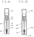
- the liquid at the bottom 102a of the liquid reservoir chamber 102 cannot be supplied to the applying portion 107 in the course of use of the liquid, and the remaining liquid becomes wasteful.
- the liquid adhering to the inner wall 102b of the liquid reservoir chamber 102 cannot be applied to the applying portion 107, either, and becomes extremely wasteful (see Fig. 52).
- the gist of the present invention resides in that the liquid reservoir chamber is constituted by an easily deformable soft bladder.
- the bladder gradually undergoes contraction as the liquid is used. Therefore, air or the like does not enter the bladder and the container keeps hygienic. Since the bladder gradually contracts as the liquid is used, the liquid can be consumed with minimum waste.
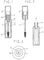
- Fig. 1 is a longitudinal sectional view for explaining an embodiment of the present invention (with an applying portion retracted).
- Fig. 2 is a longitudinal sectional view for explaining an embodiment of the present invention (with the applying portion pulled out).
- Fig. 3 is a sectional view corresponding to a portion viewed from an arrow A in Fig. 2.
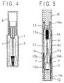
- Fig. 4 is a longitudinal sectional view showing the state where a bag body (i.e., bladder) is contracted with the use of a liquid.
- a bag body i.e., bladder
- Fig. 5 is a longitudinal sectional view for explaining another embodiment of the present invention (with the applying portion pulled in).
- Fig. 6 is a longitudinal sectional view for explaining another embodiment of the present invention (with the applying portion pulled out).
- Fig. 7 is a sectional view taken along a line X - X in Fig. 5.
- Fig. 8 is a longitudinal sectional view for explaining still another embodiment of the present invention (with the applying portion pulled in).
- Fig. 9 is a longitudinal sectional view for explaining still another embodiment of the present invention (with the applying portion pulled out).
- Fig. 10 is a sectional view taken along a line Y - Y in Fig. 8.
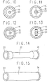
- Fig. 11 is a sectional view showing the state where the bladder is contracted with the use of the liquid.
- Fig. 12 is a sectional view showing another example of the bladder.
- Fig. 13 is a sectional view showing the state where the bladder is contracted with the use of the liquid, and corresponds to Fig. 12.
- Fig. 14 is a perspective view showing another example of the bladder.
- Fig. 15 is a perspective view showing the state where the bladder is filled with the liquid, and corresponds to Fig. 14.
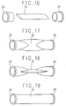
- Fig. 16 is an exploded perspective view showing still another example of the bladder.
- Fig. 17 is a perspective view showing the assembly of the bladder, and corresponds to Fig. 16.
- Fig. 18 is a side view corresponding to a portion shown in Fig. 17.
- Fig. 19 is a perspective view showing the state where the bladder shown in each of Figs. 18 and 19 is filled with the liquid.
- Fig. 20 is an exploded perspective view showing still another example of the bladder.
- Fig. 21 is a perspective view showing the assembly of the bladder and corresponds to Fig. 20.
- Fig. 22 is a perspective view showing the state where the bladder corresponding to Fig. 21 is filled with the liquid.
- Fig. 23 is an exploded perspective view showing still another example of the bladder.
- Fig. 24 is a perspective view showing the assembly of the bladder corresponding to Fig. 23.
- Fig. 25 is a perspective view showing the state where the bladder corresponding to Fig. 24 is filled with the liquid.
- Fig. 26 is an exploded perspective view showing still another example of the bladder.
- Fig. 27 is a perspective view showing the assembly of the bladder corresponding to Fig. 26.
- Fig. 28 is a longitudinal sectional view showing still another example of the bladder.
- Fig. 29 is a longitudinal sectional view showing still another example of the bladder.
- Fig. 30 is a longitudinal sectional view showing still another example of the bladder.
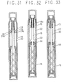
- Fig. 31 is a longitudinal sectional view showing still another example of the bladder.
- Fig. 32 is a longitudinal sectional view showing still another embodiment of the present invention.
- Fig. 33 is a longitudinal sectional view showing a modified embodiment corresponding to Fig. 32.
- Fig. 34 is a longitudinal sectional view showing another modified embodiment corresponding to Fig. 32.
- Fig. 35 is a front view showing a moving member, and corresponds to Fig. 32.
- Fig. 36 is a sectional views showing the principal portion of a moving member in another example, and corresponds to Fig. 32.
- Fig. 37 is a front view showing still another example of the moving member.
- Fig. 38 is a front view showing still another example of the moving member.
- Fig. 39 is a longitudinal sectional views showing still another example of the moving member.
- Fig. 40 is a longitudinal sectional view of the principal portions, showing a fixing method of the moving member.
- Fig. 41 is a longitudinal sectional view of the moving member, showing another fixing method of the moving member.
- Fig. 42 is a front view showing another example of the fixing method of the moving member.
- Fig. 43 is a longitudinal sectional view showing a method of packing a liquid.
- Fig. 44 is a longitudinal sectional view showing another method of packing the liquid.
- Fig. 45 is a longitudinal sectional view showing a method of fixing a tail plug to an operation knob.
- Fig. 46 is a longitudinal sectional view showing another method of fixing the tail plug to the operation knob.
- Fig. 47 is a longitudinal sectional view showing still another embodiment of the present invention.
- Fig. 48 is a longitudinal sectional view showing still another embodiment of the present invention.
- Fig. 49 is a longitudinal sectional view showing the prior art technology (with the applying portion pulled in).
- Fig. 50 is a longitudinal sectional view showing the prior art technology (with the applying portion pulled out).
- Fig. 51 is a longitudinal sectional view showing the state when the liquid is used, in the prior art technology.
- Fig. 52 is a longitudinal sectional view showing the state where the liquid is used in the prior art technology.
- An open portion 2 is defined at the upper end of a shaft 1 of the container main body, and a hole 3 is bored inside the open portion 2.
- An opening member 4 having flexibility is fixed inside the hole 3.
- a soft and flexible bag body or bladder 5 which stores therein a liquid and serves as a liquid storage member is fixed to the opening member 4.
- a screw 2a is threaded around the outer periphery of the open portion 2, and a cap 6 is removably meshed with this screw 2a.
- a coating member 7 so formed as to extend longitudinally is fixed to the inside of the cap 6.
- the applying member 7 passes through the applying member 4 and freely fits to the bladder 5 as the liquid reservoir chamber.
- the liquid is charged into the bladder 5 and applying member 7, too, is immersed in the liquid.
- Reference numeral 8 denotes an applying portion which is formed in front of the applying member 7 or is fixed to the applying member 7.
- the hole 3 is bored in the opening member 4, the hole is not a complete hole in the meaning of the term, but is defined by a criss-cross notch 3a as shown in Fig. 3. Accordingly, when this applying container is not used, the applying member 7 expands the notch 3a, thereby forming the "hole” (see Fig. 1). When the container is used, on the other hand, the notch 3a restores and is closed (see Fig. 3). To always secure the seal property, the opening member is made of a material having high flexibility such as a synthetic rubber or soft polyethylene.
- the material of the bag body 5 as the liquid reservoir chamber is a soft material such as polyethylene, polypropylene, polyvinyl chloride, polyvinylidene chloride, nylon, and so forth.
- the material does not generate permeation and drying of the liquid.
- the bladder 5 has a two-layered structure of polypropylene and polyethylene, or a three-layered structure formed by sequentially laminating polypropylene, polyvinylidene chloride and a low density polyethylene, or a structure obtained by vacuum depositing a metal such as aluminum on the surface of polyethylene.
- the front edge portion of this bladder 5 may be fixed to, or integrally formed with, the cylindrical opening member 4, or may be fixed to the inner surface of the front edge of the shaft cylinder 1 or to the opening 2.
- this fixing method includes the fixing method which utilizes plastic deformation, such as thermal fusion, ultrasonic fusion, caulking a metal or resin ring member, and so forth.
- the bladder 5 and the fixing member such as the opening member are made of the same resin and are heat-fused.
- the applying portion 8 is made of an aggregate of thin fibrous materials capable of undergoing elastic deformation, such as a synthetic fiber.
- the applying portion 8 is not necessarily limited to the one described in the embodiment, and it may be an applying member having a screw-like concavo-convex portion formed on the front surface of the applying member as illustrated in the prior art, or may be shaped into a comb-tooth shape.
- Fig. 2 shows the state where engagement between the cap 6 and the open portion 2 of the shaft 1 is released and the coating member 7 is taken out from the bladder 5. At this time, the bladder 5 is contracted by the same volume as did the applying member 7. Accordingly, any space is not defined in the bladder 5 and air does not mix into the liquid. The bladder 5 undergoes contraction similarly when the quantity of the liquid drops in the course of use.
- Fig. 4 shows the state where the cap 6 is again fitted to the shaft 1 after use, and the bladder 5 expands by the same volume as that of the applying member 7.
- the operation knob 10 is rotatably fitted to the shaft cylinder 1 in such a manner as not to move back and forth, and a projection 11a disposed at the rear part of the sliding member 3 is movably engaged with a spiral groove 10a formed in the inner hole of the operation knob 10 while a projection 11b disposed at the front part is movably engaged with a longitudinal groove 9a formed in the inner hole of the shaft cylinder 9.
- the applying member fixedly fits to the sliding member 11.
- the opening member 13 is made of a material having high flexibility such as a synthetic rubber or soft polyethylene in the same way as in the foregoing embodiment in order to reduce as much as possible the gap thereof with the applying member 12 and to always secure the seal property.
- the applying portion 12a is depicted as having a by far greater diameter than the minimum diameter portion of the opening member 13 in the drawing, excessive elastic deformation of the opening member 13 is not required.
- the applying portion 12a comprises an aggregate of thin wire-like materials capable of undergoing elastic deformation such as a synthetic fiber.
- reference symbol B denotes a cap for preventing drying.
- the inner hole portion of the shaft cylinder accommodating the applying member 12 can be utilized, as it is, as the liquid reservoir portion by paying attention to only liquid tightness at the boundary portion of each member, and can be easily utilized. According to this arrangement, however, the waste of the residual liquid becomes great, too, as already described. Therefore, the container shown in the drawings uses the soft bladder 14 made of polyethylene, polypropylene, polyvinyl chloride, nylon, etc. Preferably, this bladder does not cause permeation and drying of the liquid, and a three-layered structure formed by sequentially laminating polypropylene, polyvinyl chloride and low density polyethylene, for example, can be used.
- the open portion 14a of this bladder 14 receives the clamping force by the shaft cylinder 9 and the opening member 13 so that the liquid does not leak. Fixture by thermal fusion or bonding can be effected at the front end portion of the shaft cylinder 9.
- the center portion 14b functions as an intermediary in fixed fitting between the sliding member 11 and the applying member 12, and is fixedly interposed between them so that it can move with the integral movement of these members 11, 12.
- the inside of the bladder 14 has a two-chamber structure in front, and at the back, of the center portion 14b. However, as shown in Fig. 7, the liquid in both of these chambers can mutually communicate through a through-hole 12b bored in the applying member 12.
- the center portion 14b of the bladder 14 moves forth with the sliding member 11 and the applying member 12.
- the applying portion 12a protrudes, the volume of the front chamber of the center portion 14b becomes small, and the center portion 14b of the bladder 14 moves back with the sliding member 11 and the applying member 12.
- the applying portion 12a is pulled in, the liquid transfers through the through-hole 12b so that the volume of the rear chamber of the center portion 14b becomes small.
- a gap may be defined between the outer wall of the applying member 12 and the inner wall of the bladder 14.
- the shape may be arbitrary.
- the bladder 14 may be fixed at the rear end thereof. Further, the applying member 12 can be pulled in and out without operating the rotary knob 10.
- the applying member 12 is effected by fitting the cap B.
- the material and the shape of the applying member 12b may be suitably selected in accordance with the application.
- a projection 16a is formed at an outer intermediate portion of the operation knob 16, and a recess 15a meshing with the projection 16a is formed in the inner wall surface of the shaft cylinder 15.
- the operation knob 16 is rotatably fitted in such a manner that it does not move back and forth with respect to the shaft cylinder 15 due to the engagement between the projection 16a and the recess 15a.
- the spiral groove 16b is defined inside the operation knob 16, but this spiral groove 16 may be molded from a separate member from the operation knob 16 and be pressed into the operation knob.
- a guide member 20 is pressed into the inside of the operation knob 16, and a guide groove 21 for stopping the rotation of the sliding member 17 is formed in the guide member 20.
- Flat portions are so formed on both side of the guide groove 21 as to continue from the guide groove. This flat portion notifies the user that pull-in/out of the coating member 18 has been completed. It is formed also to prevent accidental pull-in of the applying member 18 due to external force during use when the applying portion is pulled out.
- the projection 17a is formed on the side surface of the sliding member 17, and meshes with the spiral groove 16b of the operation knob 16 through (penetration through) the guide groove 21 of the guide member 20.
- the applying member 18 is fixedly fitted to the sliding member.
- the opening member 19 and the applying member 18 are the same in material and in shape as those in the foregoing embodiments.
- Symbol B denotes a cap for preventing drying.
- This embodiment uses the bladder 22 as the liquid reservoir chamber. Though the material of this bladder 22 is the same as that of the foregoing embodiments, its fixing method is different.
- this bladder 22 is fixed to the cylindrical open portion 23, it may be fixed to the front end inner surface of the shaft cylinder 15, or may be fixed to, or formed integrally with, the opening member 15.
- the rear end portion of the bladder 22 is fixed to the liquid-tight sliding portion 24 which is in turn fixed to the intermediate portion of the shaft cylinder 15.
- the applying portion 18 slides, and an O-ring 25 is disposed so as to prevent leak of the liquid from the sliding portion.
- a projection, or the like, may be formed inside the liquid-tight sliding portion 24 in place of the O-ring 25, or the inside surface of the liquid-tight sliding portion 24 may be brought into direct and sliding contact with the outer diameter of the coating member 18 so as to prevent leak of the liquid.
- Fig. 11 shows the state where the quantity of the liquid in the liquid reservoir chamber (bladder 8) decreases due to use and the bladder 22 is contracted in the radial direction.
- the bladder When self shrinkage force is imparted on the bladder, the bladder reliably contracts with the consumption of the liquid even when the liquid has a low viscosity.
- the material for the bladder includes a synthetic rubber and a thermoplastic elastomer.
- Fig. 14 shows the bladder 22 having self shrinkage force made of a material such as an ethylene rubber or a butadiene rubber, as typified by a rubber balloon.
- the liquid is charged into the bladder 22 under the contracted state so as to inflate the bladder 22 (see Fig. 15).
- the self shrinkage force of the bladder 22 is too strong, there is the possibility that the liquid inside the bladder comes out from the open portion due to the shrinkage force of the bladder 22, regardless whether the container is used or not.
- the bladder 22 arrangement contracts down to the diameter of the applying portion 18a, the liquid adhering to the inner wall surface of the bladder 22 can be scraped off without any waste. Because the bladder 22 is made of a material having contracting property, like as a balloon, it contracts in such a manner as to restore its shape with the consumption of the liquid when the container is used.
- the bladder 22 may have a flat cylindrical shape having a fold at each side in its longitudinal direction, as shown in Fig. 16.
- the liquid is charged so as to inflate the bladder 22 in the same way as in the foregoing embodiments (Figs. 17, 18 and 19).
- the bladder 22 contract with the consumption of the liquid due to the shrinkage force brought forth by the folds.
- the charging quantity of the liquid can be increased by increasing the diameter of the bladder 22 to a diameter somewhat greater than the outer diameter of the open portion 23 and tacking and fixing its fixing portion to the open portion 23 and the later-appearing liquid-tight sliding portion 24.
- the fixing portions 23a, 24a of the bladder 22 at the open portion 23 and the liquid-tight sliding portion 24 are shaped into an oval as shown in Figs. 20 to 22, the restoring force in the folding direction of the bladder 22 becomes great, and the liquid charge quantity becomes somewhat smaller than in the foregoing embodiments but the liquid in the vicinity of the inner end surface of the opening portion 23 and the liquid-tight sliding portion 24 can be scraped by the applying portion 18a to reduce the waste.
- This embodiment is suitable for the bladder which does not undergo plastic deformation by itself unlike a rubber balloon, such as a bag body or a bladder obtained by vacuum depositing a metal such as aluminum to the surface of polyethylene.
- Figs. 23 to 25 show a modification of the embodiment described above. Tristar folds are formed on the bladder 22, and the shape of the fixing portions 23a, 24a of the bladder such as the open portion 23, too, are shaped into the tristar shape.
- This embodiment, too, is suitable for the bladder which does not undergo plastic deformation, but when the bladder has flexibility such as the rubber balloon, reliability of reduction of the diameter can be improved.
- Figs. 26 and 27 show modified examples of the bladder 22 and the open portion 23.
- the width of the center portion 22a of the bladder 22 is greater than the width at both end portions 22b, 22c, the fixing portion 23a of the open portion 23 is oval, the shape of the fixing portion 24a of the liquid-tight sliding portion 24 is round, and the bladder 22 is fixed.
- the bladder 22 is formed by bonding two sheets and their edge portions 22d are bonded by thermal fusion. Needless to say, however, the portion to be fixed to the fixing portion such as the open portion is not fused.
- a bonding method it is possible to apply an adhesive and then to bond the sheets, but preferred is the method which vacuum deposits silicon dioxide on the lower surface of polyester, disposes a polyethylene layer on the lower surface of silicon dioxide and then bonds the sheets with each other on the polyethylene layers.
- Another preferred method disposes the polyethylene layer inside polyester coated with polyvinylidene chloride, and bonds the sheets on their polyethylene layers in the same way as the method described above.
- the bladder can be heat-fused reliably to the bladder by shaping the open portion, etc., from polyethylene.
- each of these bladders 22 is fixed to the cylindrical open portion 23, but it may be fixed to the inner surface of the front end portion of the shaft cylinder 15. Alternatively, the front end portion may be fixed to, or shaped integrally with, the opening member 19.
- the rear end portion of the bladder 22 is fixed to the liquid-tight sliding portion 24 which is in turn fixed to the intermediate portion of the shaft cylinder 15. In the liquid-tight sliding portion 24, the coating portion 18 slides, and to prevent leak of the liquid from the sliding portion, the O-ring 25 is disposed.
- a projection, or the like may be formed inside the liquid-tight sliding portion 24 in place of the O-ring 25, or the inner surface of the liquid-tight sliding portion 24 may be brought into direct and sliding contact with the outer diameter of the coating member 18 so as to prevent leakage of the liquid.
- the liquid-tight sliding portion 24 is disposed movably relative to the shaft cylinder 15 and one of the ends of the bladder which contracts in the longitudinal direction is fixed to the liquid-tight sliding portion 24.
- the bladder 22 contracts in the longitudinal direction, and the light-tight sliding portion 24 causes the applying member 14 to slide, and moves in the direction of the open portion 23.
- the liquid-tight portion 24 may be biased by a resilient member such as a coil spring in the direction of the open portion 23 so as to make the liquid-tight sliding portion 24 more easily movable, as shown in Fig. 29, but needless to say, this resilient member does not invite leakage of the liquid from the open portion.
- a mountain portion 27 on the inner wall of the shaft cylinder 15 and a pawl 28 meshing with this mountain portion 27 is formed on the side surface of the liquid-tight sliding portion 24 as shown in Fig. 29.
- This is a kind of a rachet mechanism, which permits the advance of the liquid-tight sliding portion 24 but inhibits its retreat, and prevents restoration of the bladder 22 contracted as a result of use of the liquid.
- the application of the shrinkage force to the bladder 22 is particularly effective when a liquid having low fluidity but high viscosity is used.
- the residual quantity of the liquid can be by far reduced in the embodiment described in comparison with the prior art example, but another embodiment which can further reduce the residual quantity of the liquid will be explained.
- This embodiment moves forth the liquid remaining at the front part of the liquid-tight sliding portion 24 by the moving member and causing it to adhere to the applying member 18. This moving member will be explained.
- a disc-like or spiral moving member 30 is integrally formed at the intermediate part of the applying member 18, but it is preferably shaped as a separate member. Easiness of assembly is one of the reasons, and another reason is that whereas the applying member 18 is desired to be molded from a relatively rigid material, the moving member 30 is desired to be made of a soft material. Because the force acts on the applying member 18 during use, the applying member 18 is preferably made of a rigid material, but the moving member is preferably made of a soft material so that no damage is imparted to the inner surface of the bladder.
- the material of the moving member is preferably those which are relatively soft and are easily deformable, such as polyethylene, polypropylene, silicone and other synthetic rubbers.
- a disc-like moving member 31 shown in Fig. 34 is fixedly pushed into the intermediate portion of the applying member 18.
- a boss 31a, or the like may be formed at the press-in portion of the moving member 31.
- the moving member 31 may have a gear-like shape as shown in Fig. 37.
- the peripheral portion may have a reduced thickness as shown in Fig. 38.
- the peripheral portion is made soft so that it can easily undergo deformation.
- the moving member 31 may be shaped into an umbrella shape so as to easily scrape and collect the liquid, as in Fig. 39.
- the moving member 31 may cause sliding of the applying member 18. If the applying member 18 slides, damage and breakage of the inner wall of the bladder 22 can be prevented. As shown in Figs. 40, 41 and 42, sliding becomes smooth when a plurality of circumferential ribs 31b and longitudinal ribs 31c are formed at the fitting portion of the moving member 31b to the applying member 18. Even when sliding is thus made smooth, the press force for advancing the liquid is of course necessary.
- a preferred example of the removable fixing method forms circular projections 16a, 32a round the inner wall of the shaft cylinder 16 and the outer periphery of the tail plug 32 as shown in Figs. 45 and 46 and meshes them, respectively, but the method is not particularly limited to this method but various other fixing methods can be employed.
- the applying container may be the one in which a large diameter portion 18b having a somewhat greater diameter than that of the applying member 18 is formed at the applying member 18 or at the distal end of the applying portion as illustrated by the prior art technique or in Fig. 47.
- a similar effect can be obtained by using the bladder according to the present invention.
- the present invention can be applied to the applying container wherein the operation knob 16 is a mere tail plug portion (the bottom portion of the shaft cylinder 1), the applying member 18 is biased forward by a resilient member such as a coil spring and the applying member 4 protrudes upon removal of the cap B, and to the container wherein a slide piece 33 is fitted to the rear end of the applying member 18 and is moved in the longitudinal direction of the shaft cylinder 15 in place of the rotary mechanism, as shown in Fig. 48, and when the slide piece 33 is moved in the longitudinal direction of the shaft cylinder 15, the applying portion 18a is allowed to protrude from the opening member 19.
- Reference numeral 15b represents a sliding groove in which the connecting portion between the slide piece 33 and the applying member 18 slides.
- an applying member having an applying portion is stored in a liquid reservoir chamber of a container main body in such a manner that the applying portion can protrude outside the liquid reservoir chamber.
- the applying container according to the present invention employs the construction wherein the liquid reservoir chamber is constituted by the bladder in the form of a bag which can sequentially contract with the consumption of the liquid. Therefore, air, etc., does not enter the bladder and, accordingly, the applying container of the invention is hygienic and can consume the liquid substantially to the last.
Landscapes
- Coating Apparatus (AREA)
Applications Claiming Priority (13)
| Application Number | Priority Date | Filing Date | Title |
|---|---|---|---|
| JP6317393 | 1993-10-29 | ||
| JP63173/93U | 1993-10-29 | ||
| JP6317393U | 1993-10-29 | ||
| JP171938/94 | 1994-06-30 | ||
| JP17193894 | 1994-06-30 | ||
| JP17193894 | 1994-06-30 | ||
| JP197940/94 | 1994-07-29 | ||
| JP19794094 | 1994-07-29 | ||
| JP19794094 | 1994-07-29 | ||
| JP26208294A JPH08104374A (ja) | 1994-09-30 | 1994-09-30 | 塗布容器 |
| JP262082/94 | 1994-09-30 | ||
| JP26208294 | 1994-09-30 | ||
| PCT/JP1994/001786 WO1995011839A1 (fr) | 1993-10-29 | 1994-10-25 | Receptacle a revetement |
Publications (3)
| Publication Number | Publication Date |
|---|---|
| EP0677456A1 true EP0677456A1 (fr) | 1995-10-18 |
| EP0677456A4 EP0677456A4 (fr) | 1998-12-23 |
| EP0677456B1 EP0677456B1 (fr) | 2001-05-02 |
Family
ID=27464271
Family Applications (1)
| Application Number | Title | Priority Date | Filing Date |
|---|---|---|---|
| EP94930360A Expired - Lifetime EP0677456B1 (fr) | 1993-10-29 | 1994-10-25 | Receptacle a revetement |
Country Status (3)
| Country | Link |
|---|---|
| EP (1) | EP0677456B1 (fr) |
| DE (1) | DE69427162T2 (fr) |
| WO (1) | WO1995011839A1 (fr) |
Cited By (11)
| Publication number | Priority date | Publication date | Assignee | Title |
|---|---|---|---|---|
| EP0740913A1 (fr) * | 1995-05-05 | 1996-11-06 | L'oreal | Dispositif de conditionnement et d'application d'un produit de maquillage |
| WO1997007705A1 (fr) * | 1995-08-30 | 1997-03-06 | L'oreal | Ensemble de conditionnement pour mascara |
| WO1997007704A1 (fr) * | 1995-08-30 | 1997-03-06 | L'oreal | Ensemble de conditionnement transportable pour un produit tel que du mascara |
| FR2769808A1 (fr) * | 1997-10-20 | 1999-04-23 | Lvmh Rech | Dispositif applicateur de produit liquide plus ou moins visqueux ou pateux tel que du mascara |
| EP0858747A3 (fr) * | 1997-01-28 | 1999-05-19 | Henlopen Manufacturing Co., Inc. | Distributeur de produit fluide |
| EP0826321A3 (fr) * | 1996-09-02 | 1999-11-10 | Michael Schlosser | Dispositif d'application d'un produit cosmétique |
| EP1172045A2 (fr) | 1997-01-28 | 2002-01-16 | Henlopen Manufacturing Co., Inc. | Distributeur de produit fluide |
| EP1411797A4 (fr) * | 2001-07-20 | 2005-03-09 | Color Access Inc | Element rapporte comportant une partie formant contenant, destine a un conditionnement pour un produit cosmetique et conditionnement fabrique avec ce dernier |
| US7398898B2 (en) | 2001-07-20 | 2008-07-15 | Color Access, Inc. | Pouch container cosmetic package |
| US9179757B2 (en) | 2011-01-27 | 2015-11-10 | Parfums Christian Dior | Product applicator device and use thereof |
| CN112090674A (zh) * | 2020-08-25 | 2020-12-18 | 李网珍 | 一种路边树木石灰涂抹装置 |
Families Citing this family (2)
| Publication number | Priority date | Publication date | Assignee | Title |
|---|---|---|---|---|
| DE19516764A1 (de) * | 1995-05-06 | 1996-11-07 | Henkel Raycap Produktie Bv | Behälter für ein fließfähiges Produkt |
| FR2923997B1 (fr) * | 2007-11-26 | 2010-03-12 | Rexam Reboul | Systeme d'application d'un produit liquide pateux avec applicateur retractable. |
Family Cites Families (5)
| Publication number | Priority date | Publication date | Assignee | Title |
|---|---|---|---|---|
| JPS59165107U (ja) * | 1983-04-20 | 1984-11-06 | 株式会社葛飾プレス工業所 | 化粧筆 |
| JPS62136914U (fr) * | 1986-02-24 | 1987-08-28 | ||
| JPH0441102Y2 (fr) * | 1986-07-09 | 1992-09-28 | ||
| JPH0451706Y2 (fr) * | 1987-11-27 | 1992-12-04 | ||
| EP0473704A4 (en) * | 1989-05-26 | 1993-04-14 | Robert Winer | Self-pressurized container |
-
1994
- 1994-10-25 DE DE69427162T patent/DE69427162T2/de not_active Expired - Fee Related
- 1994-10-25 EP EP94930360A patent/EP0677456B1/fr not_active Expired - Lifetime
- 1994-10-25 WO PCT/JP1994/001786 patent/WO1995011839A1/fr not_active Ceased
Non-Patent Citations (2)
| Title |
|---|
| No further relevant documents disclosed * |
| See also references of WO9511839A1 * |
Cited By (22)
| Publication number | Priority date | Publication date | Assignee | Title |
|---|---|---|---|---|
| EP0740913A1 (fr) * | 1995-05-05 | 1996-11-06 | L'oreal | Dispositif de conditionnement et d'application d'un produit de maquillage |
| FR2733673A1 (fr) * | 1995-05-05 | 1996-11-08 | Oreal | Dispositif de conditionnement et d'application d'un produit de maquillage |
| KR100419300B1 (ko) * | 1995-05-05 | 2004-05-27 | 로레알 | 화장품포장및도포용기구 |
| US6474890B1 (en) | 1995-05-05 | 2002-11-05 | L'oreal | Device for packaging and applying makeup |
| FR2738126A1 (fr) * | 1995-08-30 | 1997-03-07 | Oreal | Mascara transportable |
| FR2738125A1 (fr) * | 1995-08-30 | 1997-03-07 | Oreal | Ensemble de conditionnement pour mascara |
| EP0761122A1 (fr) * | 1995-08-30 | 1997-03-12 | L'oreal | Ensemble de conditionnement transportable pour un produit tel que du mascara |
| EP0761123A1 (fr) * | 1995-08-30 | 1997-03-12 | L'oreal | Ensemble de conditionnement pour mascara |
| US5743279A (en) * | 1995-08-30 | 1998-04-28 | L'oreal | Packaging unit for a product such as mascara |
| WO1997007705A1 (fr) * | 1995-08-30 | 1997-03-06 | L'oreal | Ensemble de conditionnement pour mascara |
| WO1997007704A1 (fr) * | 1995-08-30 | 1997-03-06 | L'oreal | Ensemble de conditionnement transportable pour un produit tel que du mascara |
| EP0923894A3 (fr) * | 1995-08-30 | 1999-07-07 | L'oreal | Ensemble de conditionnement pour mascara |
| EP0826321A3 (fr) * | 1996-09-02 | 1999-11-10 | Michael Schlosser | Dispositif d'application d'un produit cosmétique |
| US6231256B1 (en) * | 1997-01-28 | 2001-05-15 | Henlopen Manufacturing Co., Inc. | Fluid material dispenser |
| EP1172045A2 (fr) | 1997-01-28 | 2002-01-16 | Henlopen Manufacturing Co., Inc. | Distributeur de produit fluide |
| EP0858747A3 (fr) * | 1997-01-28 | 1999-05-19 | Henlopen Manufacturing Co., Inc. | Distributeur de produit fluide |
| EP1172045A3 (fr) * | 1997-01-28 | 2002-12-04 | Henlopen Manufacturing Co., Inc. | Distributeur de produit fluide |
| FR2769808A1 (fr) * | 1997-10-20 | 1999-04-23 | Lvmh Rech | Dispositif applicateur de produit liquide plus ou moins visqueux ou pateux tel que du mascara |
| EP1411797A4 (fr) * | 2001-07-20 | 2005-03-09 | Color Access Inc | Element rapporte comportant une partie formant contenant, destine a un conditionnement pour un produit cosmetique et conditionnement fabrique avec ce dernier |
| US7398898B2 (en) | 2001-07-20 | 2008-07-15 | Color Access, Inc. | Pouch container cosmetic package |
| US9179757B2 (en) | 2011-01-27 | 2015-11-10 | Parfums Christian Dior | Product applicator device and use thereof |
| CN112090674A (zh) * | 2020-08-25 | 2020-12-18 | 李网珍 | 一种路边树木石灰涂抹装置 |
Also Published As
| Publication number | Publication date |
|---|---|
| EP0677456A4 (fr) | 1998-12-23 |
| DE69427162T2 (de) | 2001-08-23 |
| WO1995011839A1 (fr) | 1995-05-04 |
| DE69427162D1 (de) | 2001-06-07 |
| EP0677456B1 (fr) | 2001-05-02 |
Similar Documents
| Publication | Publication Date | Title |
|---|---|---|
| EP0677456B1 (fr) | Receptacle a revetement | |
| JP3732112B2 (ja) | 収容及びアプリケータ装置 | |
| CN100360065C (zh) | 一种盛装和施用化妆品之类产品的装置 | |
| US6883991B2 (en) | Device, system, and method for applying a product | |
| JP3907553B2 (ja) | 化粧製品などの製品の収容及び分配のための装置 | |
| US4199270A (en) | Dispenser-container brush for paste material | |
| CN1946615B (zh) | 涂敷用填充物压出容器 | |
| US8286649B2 (en) | Applicator and a packaging and applicator device including such an applicator | |
| JPH11253228A (ja) | 微粉状、液状、又はペ―スト状の製品を収納・塗布するための、ピストンを備えたアッセンブリ | |
| KR20020060060A (ko) | 가요성 벽을 구비한 화장품 용기 | |
| JP4746626B2 (ja) | マスカラの塗布及び包装装置、及び化粧品のためのその使用方法 | |
| US20040184865A1 (en) | Retractable dispenser for fluid materials | |
| US7192212B2 (en) | Application device for applying a liquid, gel-like or pasty cosmetic to the skin | |
| WO2005053457A1 (fr) | Recipient muni d'un applicateur | |
| CN100525673C (zh) | 涂敷用填充物推出容器 | |
| CN100477940C (zh) | 带涂敷体的容器 | |
| US7624741B2 (en) | Mascara packaging and applicator assembly, and its use for applying make-up | |
| JP4607746B2 (ja) | 内容物押出容器 | |
| JP4739847B2 (ja) | 充填物押出容器 | |
| JP4269104B2 (ja) | 塗布具 | |
| JPH08295374A (ja) | 塗布容器 | |
| JPH02152405A (ja) | 歯磨剤内蔵歯ブラシ | |
| JP7155428B2 (ja) | 残量防止と同時にエアタイト機能を有する化粧品容器 | |
| US20060137999A1 (en) | Cosmetic container, cosmetic applicatior, and methods of making the same | |
| JPH08104374A (ja) | 塗布容器 |
Legal Events
| Date | Code | Title | Description |
|---|---|---|---|
| PUAI | Public reference made under article 153(3) epc to a published international application that has entered the european phase |
Free format text: ORIGINAL CODE: 0009012 |
|
| 17P | Request for examination filed |
Effective date: 19950529 |
|
| AK | Designated contracting states |
Kind code of ref document: A1 Designated state(s): DE FR GB IT |
|
| A4 | Supplementary search report drawn up and despatched |
Effective date: 19981110 |
|
| AK | Designated contracting states |
Kind code of ref document: A4 Designated state(s): DE FR GB IT |
|
| 17Q | First examination report despatched |
Effective date: 19990520 |
|
| GRAG | Despatch of communication of intention to grant |
Free format text: ORIGINAL CODE: EPIDOS AGRA |
|
| GRAG | Despatch of communication of intention to grant |
Free format text: ORIGINAL CODE: EPIDOS AGRA |
|
| GRAH | Despatch of communication of intention to grant a patent |
Free format text: ORIGINAL CODE: EPIDOS IGRA |
|
| GRAH | Despatch of communication of intention to grant a patent |
Free format text: ORIGINAL CODE: EPIDOS IGRA |
|
| GRAA | (expected) grant |
Free format text: ORIGINAL CODE: 0009210 |
|
| AK | Designated contracting states |
Kind code of ref document: B1 Designated state(s): DE FR GB IT |
|
| REF | Corresponds to: |
Ref document number: 69427162 Country of ref document: DE Date of ref document: 20010607 |
|
| ITF | It: translation for a ep patent filed | ||
| ET | Fr: translation filed | ||
| REG | Reference to a national code |
Ref country code: GB Ref legal event code: IF02 |
|
| PLBE | No opposition filed within time limit |
Free format text: ORIGINAL CODE: 0009261 |
|
| STAA | Information on the status of an ep patent application or granted ep patent |
Free format text: STATUS: NO OPPOSITION FILED WITHIN TIME LIMIT |
|
| 26N | No opposition filed | ||
| PGFP | Annual fee paid to national office [announced via postgrant information from national office to epo] |
Ref country code: FR Payment date: 20021008 Year of fee payment: 9 |
|
| PGFP | Annual fee paid to national office [announced via postgrant information from national office to epo] |
Ref country code: GB Payment date: 20021023 Year of fee payment: 9 |
|
| PGFP | Annual fee paid to national office [announced via postgrant information from national office to epo] |
Ref country code: DE Payment date: 20021031 Year of fee payment: 9 |
|
| PG25 | Lapsed in a contracting state [announced via postgrant information from national office to epo] |
Ref country code: GB Free format text: LAPSE BECAUSE OF NON-PAYMENT OF DUE FEES Effective date: 20031025 |
|
| PG25 | Lapsed in a contracting state [announced via postgrant information from national office to epo] |
Ref country code: DE Free format text: LAPSE BECAUSE OF NON-PAYMENT OF DUE FEES Effective date: 20040501 |
|
| GBPC | Gb: european patent ceased through non-payment of renewal fee |
Effective date: 20031025 |
|
| PG25 | Lapsed in a contracting state [announced via postgrant information from national office to epo] |
Ref country code: FR Free format text: LAPSE BECAUSE OF NON-PAYMENT OF DUE FEES Effective date: 20040630 |
|
| REG | Reference to a national code |
Ref country code: FR Ref legal event code: ST |
|
| PG25 | Lapsed in a contracting state [announced via postgrant information from national office to epo] |
Ref country code: IT Free format text: LAPSE BECAUSE OF NON-PAYMENT OF DUE FEES;WARNING: LAPSES OF ITALIAN PATENTS WITH EFFECTIVE DATE BEFORE 2007 MAY HAVE OCCURRED AT ANY TIME BEFORE 2007. THE CORRECT EFFECTIVE DATE MAY BE DIFFERENT FROM THE ONE RECORDED. Effective date: 20051025 |