EP0677882A1 - Verfahren zur Erzeugung von elektrischer Energie aus regenerativer Biomasse - Google Patents
Verfahren zur Erzeugung von elektrischer Energie aus regenerativer Biomasse Download PDFInfo
- Publication number
- EP0677882A1 EP0677882A1 EP95101521A EP95101521A EP0677882A1 EP 0677882 A1 EP0677882 A1 EP 0677882A1 EP 95101521 A EP95101521 A EP 95101521A EP 95101521 A EP95101521 A EP 95101521A EP 0677882 A1 EP0677882 A1 EP 0677882A1
- Authority
- EP
- European Patent Office
- Prior art keywords
- biomass
- reformer
- raw gas
- gas
- module
- Prior art date
- Legal status (The legal status is an assumption and is not a legal conclusion. Google has not performed a legal analysis and makes no representation as to the accuracy of the status listed.)
- Granted
Links
Images

Classifications
-
- H—ELECTRICITY
- H01—ELECTRIC ELEMENTS
- H01M—PROCESSES OR MEANS, e.g. BATTERIES, FOR THE DIRECT CONVERSION OF CHEMICAL ENERGY INTO ELECTRICAL ENERGY
- H01M8/00—Fuel cells; Manufacture thereof
- H01M8/06—Combination of fuel cells with means for production of reactants or for treatment of residues
- H01M8/0662—Treatment of gaseous reactants or gaseous residues, e.g. cleaning
-
- C—CHEMISTRY; METALLURGY
- C01—INORGANIC CHEMISTRY
- C01B—NON-METALLIC ELEMENTS; COMPOUNDS THEREOF; METALLOIDS OR COMPOUNDS THEREOF NOT COVERED BY SUBCLASS C01C
- C01B3/00—Hydrogen; Gaseous mixtures containing hydrogen; Separation of hydrogen from mixtures containing it; Purification of hydrogen; Reversible storage of hydrogen
- C01B3/02—Production of hydrogen; Production of gaseous mixtures containing hydrogen
- C01B3/32—Production of hydrogen; Production of gaseous mixtures containing hydrogen by reaction of gaseous or liquid organic compounds with gasifying agents, e.g. water, carbon dioxide or air
-
- C—CHEMISTRY; METALLURGY
- C10—PETROLEUM, GAS OR COKE INDUSTRIES; TECHNICAL GASES CONTAINING CARBON MONOXIDE; FUELS; LUBRICANTS; PEAT
- C10J—PRODUCTION OF PRODUCER GAS, WATER-GAS, SYNTHESIS GAS FROM SOLID CARBONACEOUS MATERIAL, OR MIXTURES CONTAINING THESE GASES; CARBURETTING AIR OR OTHER GASES
- C10J3/00—Production of combustible gases containing carbon monoxide from solid carbonaceous fuels
- C10J3/46—Gasification of granular or pulverulent flues in suspension
- C10J3/463—Gasification of granular or pulverulent flues in suspension in stationary fluidised beds
-
- H—ELECTRICITY
- H01—ELECTRIC ELEMENTS
- H01M—PROCESSES OR MEANS, e.g. BATTERIES, FOR THE DIRECT CONVERSION OF CHEMICAL ENERGY INTO ELECTRICAL ENERGY
- H01M8/00—Fuel cells; Manufacture thereof
- H01M8/06—Combination of fuel cells with means for production of reactants or for treatment of residues
- H01M8/0606—Combination of fuel cells with means for production of reactants or for treatment of residues with means for production of gaseous reactants
- H01M8/0612—Combination of fuel cells with means for production of reactants or for treatment of residues with means for production of gaseous reactants from carbon-containing material
- H01M8/0643—Gasification of solid fuel
-
- C—CHEMISTRY; METALLURGY
- C10—PETROLEUM, GAS OR COKE INDUSTRIES; TECHNICAL GASES CONTAINING CARBON MONOXIDE; FUELS; LUBRICANTS; PEAT
- C10J—PRODUCTION OF PRODUCER GAS, WATER-GAS, SYNTHESIS GAS FROM SOLID CARBONACEOUS MATERIAL, OR MIXTURES CONTAINING THESE GASES; CARBURETTING AIR OR OTHER GASES
- C10J2300/00—Details of gasification processes
- C10J2300/09—Details of the feed, e.g. feeding of spent catalyst, inert gas or halogens
- C10J2300/0903—Feed preparation
-
- C—CHEMISTRY; METALLURGY
- C10—PETROLEUM, GAS OR COKE INDUSTRIES; TECHNICAL GASES CONTAINING CARBON MONOXIDE; FUELS; LUBRICANTS; PEAT
- C10J—PRODUCTION OF PRODUCER GAS, WATER-GAS, SYNTHESIS GAS FROM SOLID CARBONACEOUS MATERIAL, OR MIXTURES CONTAINING THESE GASES; CARBURETTING AIR OR OTHER GASES
- C10J2300/00—Details of gasification processes
- C10J2300/09—Details of the feed, e.g. feeding of spent catalyst, inert gas or halogens
- C10J2300/0913—Carbonaceous raw material
- C10J2300/0916—Biomass
-
- C—CHEMISTRY; METALLURGY
- C10—PETROLEUM, GAS OR COKE INDUSTRIES; TECHNICAL GASES CONTAINING CARBON MONOXIDE; FUELS; LUBRICANTS; PEAT
- C10J—PRODUCTION OF PRODUCER GAS, WATER-GAS, SYNTHESIS GAS FROM SOLID CARBONACEOUS MATERIAL, OR MIXTURES CONTAINING THESE GASES; CARBURETTING AIR OR OTHER GASES
- C10J2300/00—Details of gasification processes
- C10J2300/09—Details of the feed, e.g. feeding of spent catalyst, inert gas or halogens
- C10J2300/0953—Gasifying agents
- C10J2300/0973—Water
-
- C—CHEMISTRY; METALLURGY
- C10—PETROLEUM, GAS OR COKE INDUSTRIES; TECHNICAL GASES CONTAINING CARBON MONOXIDE; FUELS; LUBRICANTS; PEAT
- C10J—PRODUCTION OF PRODUCER GAS, WATER-GAS, SYNTHESIS GAS FROM SOLID CARBONACEOUS MATERIAL, OR MIXTURES CONTAINING THESE GASES; CARBURETTING AIR OR OTHER GASES
- C10J2300/00—Details of gasification processes
- C10J2300/16—Integration of gasification processes with another plant or parts within the plant
- C10J2300/164—Integration of gasification processes with another plant or parts within the plant with conversion of synthesis gas
- C10J2300/1643—Conversion of synthesis gas to energy
- C10J2300/1646—Conversion of synthesis gas to energy integrated with a fuel cell
-
- C—CHEMISTRY; METALLURGY
- C10—PETROLEUM, GAS OR COKE INDUSTRIES; TECHNICAL GASES CONTAINING CARBON MONOXIDE; FUELS; LUBRICANTS; PEAT
- C10J—PRODUCTION OF PRODUCER GAS, WATER-GAS, SYNTHESIS GAS FROM SOLID CARBONACEOUS MATERIAL, OR MIXTURES CONTAINING THESE GASES; CARBURETTING AIR OR OTHER GASES
- C10J2300/00—Details of gasification processes
- C10J2300/16—Integration of gasification processes with another plant or parts within the plant
- C10J2300/1671—Integration of gasification processes with another plant or parts within the plant with the production of electricity
-
- C—CHEMISTRY; METALLURGY
- C10—PETROLEUM, GAS OR COKE INDUSTRIES; TECHNICAL GASES CONTAINING CARBON MONOXIDE; FUELS; LUBRICANTS; PEAT
- C10J—PRODUCTION OF PRODUCER GAS, WATER-GAS, SYNTHESIS GAS FROM SOLID CARBONACEOUS MATERIAL, OR MIXTURES CONTAINING THESE GASES; CARBURETTING AIR OR OTHER GASES
- C10J2300/00—Details of gasification processes
- C10J2300/18—Details of the gasification process, e.g. loops, autothermal operation
- C10J2300/1853—Steam reforming, i.e. injection of steam only
-
- H—ELECTRICITY
- H01—ELECTRIC ELEMENTS
- H01M—PROCESSES OR MEANS, e.g. BATTERIES, FOR THE DIRECT CONVERSION OF CHEMICAL ENERGY INTO ELECTRICAL ENERGY
- H01M2300/00—Electrolytes
- H01M2300/0017—Non-aqueous electrolytes
- H01M2300/0065—Solid electrolytes
- H01M2300/0082—Organic polymers
-
- Y—GENERAL TAGGING OF NEW TECHNOLOGICAL DEVELOPMENTS; GENERAL TAGGING OF CROSS-SECTIONAL TECHNOLOGIES SPANNING OVER SEVERAL SECTIONS OF THE IPC; TECHNICAL SUBJECTS COVERED BY FORMER USPC CROSS-REFERENCE ART COLLECTIONS [XRACs] AND DIGESTS
- Y02—TECHNOLOGIES OR APPLICATIONS FOR MITIGATION OR ADAPTATION AGAINST CLIMATE CHANGE
- Y02E—REDUCTION OF GREENHOUSE GAS [GHG] EMISSIONS, RELATED TO ENERGY GENERATION, TRANSMISSION OR DISTRIBUTION
- Y02E60/00—Enabling technologies; Technologies with a potential or indirect contribution to GHG emissions mitigation
- Y02E60/30—Hydrogen technology
- Y02E60/50—Fuel cells
-
- Y—GENERAL TAGGING OF NEW TECHNOLOGICAL DEVELOPMENTS; GENERAL TAGGING OF CROSS-SECTIONAL TECHNOLOGIES SPANNING OVER SEVERAL SECTIONS OF THE IPC; TECHNICAL SUBJECTS COVERED BY FORMER USPC CROSS-REFERENCE ART COLLECTIONS [XRACs] AND DIGESTS
- Y02—TECHNOLOGIES OR APPLICATIONS FOR MITIGATION OR ADAPTATION AGAINST CLIMATE CHANGE
- Y02P—CLIMATE CHANGE MITIGATION TECHNOLOGIES IN THE PRODUCTION OR PROCESSING OF GOODS
- Y02P20/00—Technologies relating to chemical industry
- Y02P20/10—Process efficiency
- Y02P20/133—Renewable energy sources, e.g. sunlight
Definitions
- the invention relates to a method and a system for generating electrical energy from regenerative biomass produced from plants, a hydrogen-containing raw gas being generated in a reformer, a fuel gas with a high hydrogen content being formed from the raw gas in a raw gas processing device and with a power generation module electrical energy is generated from the clean fuel gas using PEM fuel cells.
- the biomass can be produced from plants grown specifically for the purpose of energy production.
- the biomass can also be formed from plant waste.
- PEM stands for "proton exchange membrane” and / or for "polymer-electrolyte membrane", which are both synonyms.
- the basic structure of PEM fuel cells is a polymer membrane with permeable catalytic electrodes on both sides of the membrane.
- a cathode compartment and an anode compartment are assigned to the cathode and the anode.
- a hydrogen-containing fuel gas is supplied to the anode compartment, the hydrogen being oxidized to protons at the anode.
- the protons have a high mobility in the polymer membrane and migrate to the cathode, where z.
- a method and a device of the type mentioned at the outset are known from the literature reference "Department of Energy (DOE), November 1992, DE 93000009".
- DOE Department of Energy
- methanol is first produced from the biomass.
- the methanol is then converted to a hydrogen-containing raw gas in a reformer.
- carbon monoxide formed during the conversion is removed from the raw gas, with no further use of the carbon monoxide.
- the largely pure carbon monoxide-free fuel gas obtained is then converted into electricity in the PEM fuel cells.
- a disadvantage of this known method is that methanol must first be formed from the biomass in a complex manner, that the carbon monoxide is lost in spite of its calorific value, and in particular that no modular structure is set up with one another to match and adjust the operating parameters of different modules.
- the invention is based on the technical problem of specifying a method which makes better use of the energy content of the biomass and works reliably with a long service life, and a system for carrying out this method.
- C4 plants are plants that bind four carbon atoms during the photosynthetic conversion of carbon dioxide.
- Perennial plants are plants that form a distinctive root system and grow for several years.
- Perennating C4 plants are characterized in that the conversion of carbon dioxide into biomass is particularly effective, that the specific yield is particularly high and in particular that less fertilization is required. The latter is of particular importance in the context of the invention, since the small amounts of fertilizer can significantly reduce disruptive sulfur, chlorine and alkali compounds in the biomass.
- a biomass production module is an agricultural area on which the biomass is cultivated taking into account feature a).
- the biomass production module advantageously has a pelletizing device.
- a reformer is referred to as allothermic, to which the process heat required for the gasification reactions is supplied from the outside.
- the residence time of the biomass and / or the raw gas in the reformer can be easily adjusted by selecting and coordinating the flow velocity of the water vapor, the operating pressure, the temperature zone distribution and the biomass particle size.
- the optimal coordination of the parameters according to feature d) is also not difficult to determine by experiment.
- a higher operating temperature of the fuel cell requires a higher water content in the fuel clean gas in order to keep the polymer membrane sufficiently moist. This in turn makes the calorific value of the pure fuel gas reduced.
- a reduced calorific value of the clean fuel gas can be compensated for by increasing the pressure of the clean fuel gas.
- the parameter-based coordination according to feature d) can also take into account the carbon monoxide content of the pure fuel gas, provided that significant amounts of carbon monoxide occur at all within the limits of feature c).
- the plants are fertilized free of ammonium sulfate and free of potassium chloride.
- the sulfur and chlorine content in the biomass is very low.
- the potassium content can also be reduced, if only to a lesser extent.
- the reformer is designed as a fluidized bed reactor and is operated at a temperature of 650 to 900 ° C., preferably about 750 ° C., and a pressure of 1.5 to 5 bar, preferably about 3 bar.
- the residence time of the biomass in the reformer is adjusted so that the tar content of the raw gas is below 0.1%. Under these operating conditions, the raw gas is practically free from annoying tar and alkali compounds. If the reformer operates optimally, the tar content can even be reduced to below 0.5 ppm.
- the tar formed in the biomass gasification with respect to the quantitative and qualitative composition of tar formed in coal gasification. Tar from biomass gasification is apparently easier to dismantle or gasify in the reformer.
- this fine dust can be removed by means of a filter device, e.g. B. a cyclone filter, are separated from the raw gas.
- a filter device e.g. B. a cyclone filter
- a raw gas with approximately equal parts by volume of hydrogen and carbon monoxide is generated in the reformer by setting the mass ratio of steam / biomass to less than 0.3.
- the steam / biomass mass ratio can also be set to more than 1.3.
- the hydrogen / carbon monoxide volume ratio is more than 3.
- the formation of the fuel clean gas takes place in both cases in the raw gas processing module by alternately reducing an oxidized metal sponge using the raw gas and then oxidizing the reduced metal sponge using steam.
- Iron sponge is advantageously used as the metal sponge.
- a raw gas with a hydrogen / carbon monoxide volume ratio of more than 3 is generated in the reformer by setting the mass ratio of steam / biomass to more than 1.3, the formation of the fuel clean gas in the raw gas processing module by enrichment of the hydrogen to at least 99 vol.% In the fuel clean gas is carried out by means of the PSA method with at least 2 adsorption reactors and the fuel clean gas is mixed with the amount of water vapor required for the permanent operation of the PEM fuel cell.
- PSA stands for "pressure swing adsorption.” In the PSA method, the raw gas flows through a first adsorption reactor under high pressure.
- the hydrogen in the raw gas is adsorbed considerably less than the other, mostly polar, raw gas components.
- a fuel clean gas with the specified hydrogen content flows out of the first adsorption reactor.
- a second adsorption reactor previously operated in the manner just described, is expanded in the counterflow direction, the undesired adsorbed components of the raw gas flowing out. If necessary, the second can then Adsorption reactor are flushed, for example with fuel gas.
- the adsorption reactors are preferably designed as molecular sieve reactors. Since the fuel clean gas contains practically no components besides the hydrogen, it is necessary to add water vapor to prevent the polymer membranes of the PEM fuel cells from drying out.
- a raw gas can be generated at 750 ° C. and 3 bar with approximately 0.29% methane, approximately 18% carbon monoxide, approximately 20% carbon dioxide and approximately 62% hydrogen. Even if the reaction equilibria are not established in the reformer, the methane content is generally less than 7% (gas fractions are always understood as vol.%). The low methane content is of particular importance here, as a result of which a good energy yield is achieved and as a result of which there is no need for complex methane separation. If at all necessary, a methane separation device of simple type and with small dimensions can be set up.
- the embodiment according to claim 6 is also characterized by a particularly low methane content in the raw gas. This is not more than 7% by volume, but usually considerably less.
- All of the exemplary embodiments of the method according to the invention are characterized in that, owing to the modular structure and the connection of the modules to a system, control or regulation of the parameter-specific operating conditions of the individual modules can be coordinated such that the system as a whole is operated optimally.
- the power generation in the power generation module is largely decoupled from the raw gas generation in the reformer module in terms of control technology.
- the metal sponge also functions as an intermediate store.
- a hydrogen storage device of a conventional type can additionally be provided in the raw gas processing module for the purpose of said control decoupling.
- the method according to the invention works with a considerably improved efficiency.
- the energy content of the biomass is optimally used.
- the invention also relates to a system for carrying out the method according to claim 8 or claim 9.
- a pelletizing device 7 is set up in the context of the biomass production module 1.
- a metering device 8 for metering the biomass and a filter device 9 for separating fine dust from the raw gas are set up.
- the allothermal reformer 3 is supplied with water vapor in the amount required for optimal gasification of the biomass via a water vapor feed 10. The water vapor is brought to the required temperature by means of heat exchangers 11 and 12. The heat exchanger 11 is operated with the heat of the raw gas.
- the heating of the water vapor in the heat exchanger 12 is carried out by burning part of the fuel gas and / or the exhaust gas from the raw gas processing module 4. It is understood that the exhaust gas from this combustion may be processed in an environmentally friendly manner in an exhaust gas purifier 13.
- the fuel cell 6 has in particular a polymer membrane 14 and an anode 15 and a cathode 16.
- the fuel clean gas is passed in the anode space 17 via the anode 15.
- a cathode space 18 is set up at the cathode, through which an oxidizing agent, for example atmospheric oxygen, is passed.
- the exhaust line 19 of the power generation module 5 escapes water or water vapor, which is practically free of environmentally harmful pollutants.
- An inverter 20 for generating conventional mains alternating current is connected to the anode 15 and cathode 16 of the fuel cell 6.
- the raw gas processing module 4 has at least two metal sponge reactors 21 with metal sponges 22.
- the metal sponges 22 are iron sponges.
- the raw gas processing module 4 is connected to the steam supply 10 via the steam connection 27.
- lines and switchable valves for alternate oxidation or reduction of the two metal sponge reactors are set up in the schematically indicated manner.
- the raw gas processing module 4 has at least two adsorption reactors 23. These are equipped with molecular sieves 24. Furthermore, at least one compressor 25 and a relaxation device 26 are set up. The clean fuel gas flowing out of the raw gas processing module 4 is adjusted in a pressure control and humidification device 27 to the desired pressure and the desired water content.
- biomass is produced by growing perennial C4 plants.
- the plants are fertilized free of ammonium sulfate and potassium chloride and the biomass that can be produced from the plants is low in sulfur and low in chlorine.
- This biomass is shaped into pellets in the pelletizing device 7.
- the biomass shaped in this way is gasified in a reformer module 2 to a hydrogen-containing raw gas.
- the reformer module 2 works with at least one allothermal reformer 3, the reformer 3 being supplied with water vapor as a gasifying agent.
- the dwell time of the biomass and / or the raw gas in the reformer 3 and the pressure and temperature in the reformer 3 are set so that biomass-based alkali compounds with ashes can be removed from the reformer 3 and that tar which forms as an intermediate product in the reformer 3 essentially forms carbon oxides and hydrogen is gasified.
- the ash is removed from the reformer 3 via the ash extraction 28.
- the reformer 3 are designed as fluidized bed reactors and are operated at a temperature of 750 ° C and a pressure of about 3 bar. Specifically, the residence time of the biomass in the reformer 3 is set so that the tar content of the raw gas is below 0.5 ppm. After the separation of entrained alkali-containing fine dust in the filter device 9, the resulting raw gas is fed to the raw gas processing module 4 to form a clean fuel gas. In the raw gas processing module, the fuel clean gas with a high hydrogen content and a carbon oxide content of less than 5 ppm is formed. Electrical energy is generated in the power generation module 5 from the clean fuel gas. The conversion of the fuel gas into electricity takes place in detail by means of at least one PEM fuel cell 6, the operating temperature of the fuel cell 6, the water content of the fuel gas and the pressure of the fuel gas being coordinated with one another with the provision of an optimal power density.
- a raw gas with approximately equal proportions of hydrogen and carbon monoxide is generated in the reformer 3 by setting the mass ratio of steam / biomass to less than 0.3.
- the fuel clean gas is carried out from this raw gas in the raw gas processing module 4 by alternately reducing an oxidized metal sponge 22 by means of the raw gas and then oxidizing the reduced metal sponge 22 by means of water vapor.
- This mode of operation is particularly advantageous in terms of energy, inter alia because little steam is required.
- a raw gas with a hydrogen / carbon monoxide ratio of more than 3 is produced in the reformer 3 by setting the mass ratio of steam / biomass to more than 1.5, the formation of the fuel clean gas in the raw gas processing module 4 by enrichment of the hydrogen to at least 99% by volume in the fuel clean gas is carried out by means of the PSA method with at least two adsorption reactors 23.
- the PSA method can be carried out in such a way that the hydrogen is enriched to 99.9% by volume or more.
- the fuel clean gas is mixed with the amount of water vapor required for the permanent operation of the PEM fuel cell 6.
Landscapes
- Chemical & Material Sciences (AREA)
- Engineering & Computer Science (AREA)
- Organic Chemistry (AREA)
- Chemical Kinetics & Catalysis (AREA)
- General Chemical & Material Sciences (AREA)
- Combustion & Propulsion (AREA)
- Life Sciences & Earth Sciences (AREA)
- Manufacturing & Machinery (AREA)
- Sustainable Development (AREA)
- Sustainable Energy (AREA)
- Electrochemistry (AREA)
- Health & Medical Sciences (AREA)
- Oil, Petroleum & Natural Gas (AREA)
- General Health & Medical Sciences (AREA)
- Inorganic Chemistry (AREA)
- Fuel Cell (AREA)
- Electrical Discharge Machining, Electrochemical Machining, And Combined Machining (AREA)
- Hydrogen, Water And Hydrids (AREA)
- Electric Propulsion And Braking For Vehicles (AREA)
- Physical Or Chemical Processes And Apparatus (AREA)
- Developing Agents For Electrophotography (AREA)
- Saccharide Compounds (AREA)
- Organic Low-Molecular-Weight Compounds And Preparation Thereof (AREA)
- Processing Of Solid Wastes (AREA)
Abstract
Description
- Die Erfindung betrifft ein Verfahren sowie ein System zur Erzeugung von elektrischer Energie aus regenerativer, aus Pflanzen erzeugter Biomasse, wobei in einem Reformer ein wasserstoffhaltiges Rohgas erzeugt wird, wobei in einer Rohgasaufbereitungsvorrichtung aus dem Rohgas ein Brennstoffreingas mit hohem Wasserstoffanteil gebildet wird und wobei in einem Verstromungsmodul mit PEM-Brennstoffzellen aus dem Brennstoffreingas elektrische Energie erzeugt wird. - Die Biomasse kann aus eigens zum Zwecke der Energieerzeugung angebauten Pflanzen erzeugt werden. Die Biomasse kann aber auch mit planzlichen Abfallstoffen gebildet werden. Die Bezeichnung "PEM" steht für "proton exchange membrane" und/oder für "polymer-electrolyte membrane", welches beides Synonyme sind. PEM-Brennstoffzellen weisen vom grundsätzlichen Aufbau her eine polymere Membran mit permeabelen katalytischen Elektroden auf beiden Seiten der Membran auf. Dadurch ist auf einer Seite der Membran die Kathode und auf der anderen Seite der Membran die Anode gebildet. Der Kathode und der Anode sind ein Kathodenraum und ein Anodenraum zugeordnet. Dem Anodenraum wird ein wasserstoffhaltiges Brennstoffgas zugeführt, wobei der Wasserstoff an der Anode zu Protonen oxidiert wird. Die Protonen haben in der Polymermembran eine hohe Beweglichkeit und wandern zur Kathode, wo z. B. dem Kathodenraum zugeführter Luftsauerstoff zu Wasser reduziert wird. Da die Polymermembran elektrisch isolierend ist, läßt sich aufgrund dieser chemischen Prozesse ein Gleichstrom von den Elektroden abnehmen, welcher gegebenenfalls in eine übliche Netz-Wechselspannung umgewandelt werden kann. Nähere Einzelheiten zu PEM-Brennstoffzellen sind beispielsweise dem US-Buch "Fuel Cells, a Handbook", K. Chinoshita, Lawrence Berkeley Laboratory, Berkeley, Carlifornia, USA, 1988, Kapitel 6.2, entnehmbar.
- Ein Verfahren und eine Vorrichtung der eingangs genannten Art sind aus der Literaturstelle "Department of Energy (DOE), November 1992, DE 93000009" bekannt. Bei dem insofern bekannten Verfahren wird zunächst aus der Biomasse Methanol hergestellt. Das Methanol wird dann in einem Reformer zu einem wasserstoffhaltigen Rohgas umgewandelt. In einer Rohgasaufbereitungsvorrichtung wird bei der Umwandlung gebildetes Kohlenmonoxid aus dem Rohgas entfernt, wobei keine weitere Nutzung des Kohlenmonoxids erfolgt. Das erhaltene insofern weitgehend kohlenmonoxidfreie Brennstoffreingas wird schließlich in den PEM-Brennstoffzellen verstromt. Nachteilig bei diesem bekannten Verfahren ist, daß aus der Biomasse zunächst auf aufwendige Weise Methanol gebildet werden muß, daß das Kohlenmonoxid trotz seines Brennwertes verloren wird und insbesondere, daß kein modularer Aufbau mit einer Abstimmung und Einstellung der Betriebsparameter unterschiedlicher Module aufeinander eingerichtet ist.
- Der Erfindung liegt das technische Problem zugrunde ein Verfahren, welches den Energiegehalt der Biomasse besser ausnutzt und zuverlässig mit hoher Standzeit arbeitet, sowie ein System zur Durchführung dieses Verfahrens anzugeben.
- Zur Lösung dieser Aufgabe lehrt die Erfindung ein Verfahren zur Erzeugung von elektrischer Energie aus regenerativer, aus Pflanzen erzeugter Biomasse, insbesondere aus Biomasse perennierender C₄-Pflanzen, wobei in einem Biomasse-Erzeugungsmodul Biomasse erzeugt wird, wobei in einem Reformermodul die Biomasse zu einem wasserstoffhaltigen Rohgas vergast wird, wobei in einem Rohgasaufbereitungsmodul aus dem Rohgas ein Brennstoffreingas mit hohem Wasserstoffanteil gebildet wird und wobei in einem Verstromungsmodul aus dem Brennstoffreingas elektrische Energie erzeugt wird, mit der folgenden Merkmalskombination:
- a) mit dem Biomasse-Erzeugungsmodul wird durch geeignete Düngung der Pflanzen schwefelarme und chlorarme Biomasse erzeugt,
- b) das Reformermodul arbeitet mit zumindest einem allothermen Reformer, wobei dem Reformer Wasserdampf als Vergasungsmittel zugeführt wird, wobei die Verweilzeit der Biomasse und/oder des Rohgases im Reformer sowie Druck und Temperatur im Reformer so eingestellt werden, daß biomassebürtige Alkaliverbindungen mit entstehender Asche aus dem Reformer abführbar sind und wobei sich als Zwischenprodukt bildender Teer in dem Reformer im wesentlichen zu Kohlenoxiden und Wasserstoff vergast wird,
- c) in dem Rohgasaufbereitungsmodul wird ein Brennstoffreingas mit einem Gehalt an Kohlenoxiden von weniger als 1 % gebildet,
- d) das Brennstoffreingas wird in dem Verstromungsmodul mittels zumindest einer PEM-Brennstoffzelle verstromt, wobei die Betriebstemperatur der PEM-Brennstoffzelle, der Wassergehalt des Brennstoffreingases und der Druck des Brennstoffreingases mit der Maßgabe einer hohen Leistungsdichte aufeinander abgestimmt werden.
- C₄-Pflanzen sind Pflanzen, welche während der fotosynthetischen Umwandlung von Kohlendioxid vier Kohlenstoffatome binden. Perennierende Pflanzen sind Pflanzen, welche ein ausgeprägtes Wurzelwerk bilden und mehrjährig wachsen. Perennierende C₄-Pflanzen zeichnen sich dadurch aus, daß die Umwandlung von Kohlendioxid in Biomasse besonders effektiv erfolgt, daß der spezifische Ertrag besonders hoch ist und insbesondere daß weniger Düngung erforderlich ist. Letzterem kommt im Rahmen der Erfindung besondere Bedeutung zu, da sich aufgrund der geringen Düngemittelmengen störende Schwefel-, Chlor- und Alkaliverbindungen in der Biomasse erheblich reduzieren lassen. Ein Biomasse-Erzeugungsmodul ist eine landwirtschaftliche Anbaufläche, auf welcher die Biomasse unter Beachtung des Merkmals a) kultiviert wird. Vorteilhafterweise weist das Biomasse-Erzeugungsmodul eine Pelletierungseinrichtung auf. Als allotherm wird ein Reformer bezeichnet, welchem die für die Vergasungsreaktionen erforderliche Prozeßwärme von außen zugeführt wird. Die Verweilzeit der Biomasse und/oder des Rohgases im Reformer läßt sich unschwer einstellen durch Auswahl und Abstimmung der Anströmgeschwindigkeit des Wasserdampfes, des Betriebsdruckes, der Temperaturzonenverteilung sowie der Biomasse-Partikelgröße. Die optimale Abstimmung der Parameter gemäß Merkmal d) ist ebenfalls unschwer durch Versuche zu ermitteln. Eine höhere Betriebstemperatur der Brennstoffzelle erfordert einen höheren Wassergehalt im Brennstoffreingas um die Polymermembran ausreichend feucht zu halten. Hierdurch wiederum wird der Brennwert des Brennstoffreingases reduziert. Ein reduzierter Brennwert des Brennstoffreingases läßt sich durch eine Erhöhung des Drucks des Brennstoffreingases kompensieren. Die parametermäßige Abstimmung gemäß Merkmal d) kann aber auch unter Berücksichtigung des Kohlenmonoxidgehaltes des Brennstoffreingases erfolgen, sofern in den Grenzen des Merkmals c) nennenswerte Mengen an Kohlenmonoxid überhaupt entstehen. Die Leistungsdichte ist um so höher, je geringer der Kohlenmonoxidgehalt des Brennstoffreingases ist. Höhere Kohlenmonoxidgehalte lassen sich durch eine höhere Betriebstemperatur der Brennstoffzelle ausgleichen. Die Betriebstemperatur der Brennstoffzelle muß jedenfalls stets unter der Glastemperatur der Polymermembran bleiben.
- In einer bevorzugten Ausführungsform des Verfahrens werden die Pflanzen ammoniumsulfatfrei und kaliumchloridfrei gedüngt. Hierdurch ist der Gehalt an Schwefel und Chlor in der Biomasse sehr gering. Auch der Kaliumgehalt ist reduzierbar, wenn auch nur in geringerem Umfang.
- Im einzelnen ist der Reformer als Wirbelbettreaktor ausgebildet und wird bei einer Temperatur von 650 bis 900° C, vorzugsweise etwa 750° C, und einem Druck von 1,5 bis 5 bar, vorzugsweise etwa 3 bar, betrieben. Die Verweilzeit der Biomasse im Reformer wird so eingestellt, daß der Teergehalt des Rohgases unter 0,1 % liegt. Unter diesen Betriebsbedingungen ist das Rohgas praktisch frei von störendem Teer sowie von Alkaliverbindungen. Bei optimaler Betriebsweise des Reformers läßt sich der Teergehalt sogar auf unter 0,5 ppm reduzieren. Von besonderer Bedeutung hierfür ist, daß der bei der Biomassevergasung gebildete Teer sich hinsichtlich der quantitativen und qualitativen Zusammensetzung von bei der Kohlevergasung gebildeten Teer unterscheidet. Teer aus der Biomassevergasung läßt sich im Reforder offenbar leichter zerlegen bzw. vergasen. Zudem findet in dem Reformer und/oder in Leitungen des Reformermoduls keine Verschlackung oder Anbackung von Material aufgrund von Alkaliverbindungen statt. Sofern dennoch in geringstem Maße alkalihaltiger Feinstaub von dem Rohgas mitgeschleppt wird, kann dieser Feinstaub mittels einer Filtereinrichtung, z. B. eines Zyklonfilters, aus dem Rohgas abgeschieden werden.
- In einer bevorzugten Ausführungsform der Erfindung wird in dem Reformer ein Rohgas mit etwa gleichen Volumenanteilen Wasserstoff und Kohlenmonoxid erzeugt durch Einstellung des Massenverhältnisses Dampf/Biomasse auf weniger als 0,3. Es kann aber auch mit einer Einstellung des Massenverhältnisses Dampf/Biomasse auf mehr als 1,3 gearbeitet werden. Dann beträgt das Wasserstoff/Kohlenmonoxid-Volumenverhältnis mehr als 3. Die Bildung des Brennstoffreingases erfolgt in beiden Fällen in dem Rohgasaufbereitungsmodul durch wechselweise Reduktion eines oxidierten Metallschwamms mittels des Rohgases und anschließender Oxidation des reduzierten Metallschwamms mittels Wasserdampf. Als Metallschwamm wird vorteilhafterweise Eisenschwamm verwendet. Ebenso kann jedoch mit anderen unedelen Metallen, beispielsweise Zink oder Mangan, gearbeitet werden. Bei der Reduktion des oxidierten Metallschwamms erfolgt die Reduktion durch Oxidation von Wasserstoff zu Wasser sowie von Kohlenmonoxid zu Kohlendioxid. Bei der Oxidation des reduzierten Metallschwamms mit Wasserdampf entsteht Wasserstoff. Im Ergebnis entsteht in diesem Ausführungsbeispiel ein Brennstoffreingas welches aus Wasserstoff und Wasserdampf besteht und ansonsten praktisch frei von anderen Bestandteilen ist. Der Wasserdampf stört im Brennstoffreingas grundsätzlich nicht, da beim Betrieb einer PEM-Brennstoffzelle ohnehin Wasser zur Aufrechterhaltung der Feuchtigkeit der Polymermembran zugeführt werden muß. Es versteht sich, daß der Wassergehalt des Brennstoffreingases gegebenenfalls durch Teilkondensation optimiert werden kann.
- In einer anderen Ausführungsform wird in dem Reformer ein Rohgas mit einem Wasserstoff/Kohlenmonoxid-Volumenverhältnis von mehr als 3 erzeugt durch Einstellung des Massenverhältnisses Dampf/Biomasse auf mehr als 1,3, wobei die Bildung des Brennstoffreingases in dem Rohgasaufbereitungsmodul durch Anreicherung des Wasserstoffs auf zumindest 99 Vol.-% im Brennstoffreingas mittels der PSA-Methode mit zumindest 2 Adsorptionsreaktoren durchgeführt wird und wobei das Brennstoffreingas mit der zum dauerhaften Betrieb der PEM-Brennstoffzelle erforderlichen Menge an Wasserdampf versetzt wird. Die Bezeichnung "PSA" steht für "pressure swing adsorption." Bei der PSA-Methode wird ein erster Adsorptionsreaktor unter hohem Druck von dem Rohgas durchströmt. Dabei wird der Wasserstoff des Rohgases aufgrund seiner chemisch-physikalischen Eigenschaften erheblich schlechter adsorbiert als die weiteren, meist polaren Rohgasbestandteile. Im Ergebnis entströmt dem ersten Adsorptionsreaktor ein Brennstoffreingas mit dem angegebenen Wasserstoffanteil. Ein zweiter, zuvor in der soeben geschilderten Weise betriebener Adsorptionsreaktor wird in Gegenstromrichtung entspannt, wobei die unerwünschten adsorbierten Bestandteile des Rohgases ausströmen. Gegebenenfalls kann anschließend der zweite Adsorptionsreaktor gespült werden, beispielsweise mit Brennstoffreingas. Die Adsorptionsreaktoren sind vorzugsweise als Molekularsiebreaktoren ausgeführt. Da das Brennstoffreingas praktisch keine Bestandteile neben dem Wasserstoff enthält, ist es erforderlich Wasserdampf zuzusetzen um ein Austrocknen der Polymermembranen der PEM-Brennstoffzellen zu verhindern. Wird der Reformer gemäß diesem Ausführungsbeispiel betrieben, so ist bei 750° C und 3 bar ein Rohgas erzeugbar mit etwa 0,29 % Methan, etwa 18 % Kohlenmonoxid, etwa 20 % Kohlendioxid und etwa 62 % Wasserstoff. Selbst wenn sich im Reformer die Reaktionsgleichgewichte nicht einstellen, beträgt der Methangehalt in der Regel wenger als 7 % (Gasanteile verstehen sich stets als Vol.-%). Von besonderer Bedeutung ist hierbei der geringe Methananteil, wodurch eine gute Energieausbeute erzielt wird und wodurch auf eine aufwendige Methanabscheidung verzichtet werden kann. Sofern überhaupt noch erforderlich kann eine Methanabscheidevorrichtung einfacher Art und mit geringer Dimensionierung eingerichtet sein. Auch die Ausführungsform gemäß Patentanspruch 6 zeichnet sich durch einen besonders geringen Methananteil in dem Rohgas aus. Dieser beträgt nicht mehr als 7 Vol.-%, meist jedoch erheblich weniger.
- Alle Ausführungsbeispiele des erfindungsgemäßen Verfahrens zeichnen sich dadurch aus, daß aufgrund des modularen Aufbaus sowie der Verbindung der Module zu einem System eine Steuerung bzw. Regelung der parametermäßigen Betriebsbedingungen der einzelnen Module so abgestimmt werden können, daß das System insgesamt optimal betrieben wird. Im einzelnen ist es ohne weiteres möglich Steuer- und Regelkreise zwischen dem Reformermodul und dem Rohgasaufbereitungsmodul einerseits und dem Rohgasaufbereitungsmodul und dem Verstromungsmodul andererseits einzurichten. Dadurch ist die Stromerzeugung in dem Verstromungsmodul regeltechnisch weitgehend von der Rohgaserzeugung im Reformermodul entkoppelt. Im Ausführungsbeispiel gemäß Patentanspruch 6 funktioniert dabei der Metallschwamm zusätzlich gleichsam als Zwischenspeicher. In dem Ausführungsbeispiel gemäß Anspruch 7 kann zum Zwecke der genannten regeltechnischen Entkopplung zusätzlich ein Wasserstoffspeicher üblicher Bauart im Rohgasaufbereitungsmodul vorgesehen sein. Im Ergebnis arbeitet das erfindungsgemäße Verfahren mit einem erheblich verbesserten Wirkungsgrad. Der Energiegehalt der Biomasse wird optimal ausgenutzt.
- Gegenstand der Erfindung ist auch ein System zur Durchführung des erfindungsgemäßen Verfahrens gemäß Patentanspruch 8 oder Patentanspruch 9.
- Im folgenden wird die Erfindung anhand von lediglich Ausführungsbeispiele darstellenden Zeichnungen näher erläutert. Es zeigen:
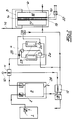
- Fig. 1
- ein System zur Durchführung des erfindungsgemäßen Verfahrens mit Metallschwammreaktoren im Rohgasaufbereitungsmodul und
- Fig. 2
- ein System zur Durchführung des erfindungsgemäßen Verfahrens mit Adsorptionsreaktoren im Rohgasaufbereitungsmodul.
- Das System zur Durchführung des erfindungsgemäßen Verfahrens gemäß der Fig. 1 und 2 weist vom grundsätzlichen Aufbau her ein Biomasse-Erzeugungsmodul 1, ein Reformermodul 2 mit zumindest einem allothermen Reformer 3, ein Rohgasaufbereitungsmodul 4 und ein Verstromungsmodul 5 mit zumindest einer PEM-Brennstoffzelle 6 auf. Im einzelnen ist im Rahmen des Biomasse-Erzeugungsmoduls 1 eine Pelletiereinrichtung 7 eingerichtet. Im Rahmen des Reformermoduls 2 sind zumindest eine Dosiereinrichtung 8 zur Dosierung der Biomasse und eine Filtereinrichtung 9 zur Abtrennung von Feinstaub aus dem Rohgas eingerichtet. Dem allothermen Reformer 3 wird über eine Wasserdampfzuführung 10 Wasserdampf in der für die optimale Vergasung der Biomasse erforderlichen Menge zugeführt. Dabei wird der Wasserdampf mittels Wärmetauscher 11 und 12 auf die erforderliche Temperatur gebracht. Der Wärmetauscher 11 wird mit der Wärme des Rohgases betrieben. Die Erhitzung des Wasserdampfes im Wärmetauscher 12 wird durch Verbrennung eines Teils des Brennstoffreingases und/oder des Abgases aus dem Rohgasaufbereitungsmodul 4 durchgeführt. Es versteht sich, daß das Abgas aus dieser Verbrennung ggf. in einer Abgasreinigung 13 umweltverträglich aufgearbeitet wird. Die Brennstoffzelle 6 weist im einzelnen eine Polymermembran 14 sowie eine Anode 15 und eine Kathode 16 auf. Das Brennstoffreingas wird im Anodenraum 17 über die Anode 15 geleitet. Bei der Kathode ist ein Kathodenraum 18 eingerichtet, durch welchen ein Oxidationsmittel, beispielsweise Luftsauerstoff, geleitet wird. Der Abgasleitung 19 des Verstromungsmoduls 5 entweicht Wasser bzw. Wasserdampf, welches praktisch frei von umweltschädlichen Schadstoffen ist. An die Anode 15 und Kathode 16 der Brennstoffzelle 6 ist ein Wechselrichter 20 zur Erzeugung von üblichem Netz-Wechselstrom angeschlossen.
- In dem Ausführungsbeispiel Fig. 1 weist das Rohgasaufbereitungsmodul 4 zumindest zwei Metallschwammreaktoren 21 mit Metallschwämmen 22 auf. Im Ausführungsbeispiel sind die Metallschwämme 22 Eisenschwämme. Das Rohgasaufbereitungsmodul 4 ist über den Wasserdampfanschluß 27 an die Wasserdampfzufuhr 10 angeschlossen. Im einzelnen sind Leitungen und umschaltbare Ventile zur wechselweisen Oxidation bzw. Reduktion der beiden Metallschwammreaktoren in der schematisch angedeuteten Weise eingerichtet.
- In dem Ausführungsbeispiel Fig. 2 weist das Rohgasaufbereitungsmodul 4 zumindest zwei Adsorptionsreaktoren 23 auf. Diese sind mit Molekularsieben 24 ausgerüstet. Weiterhin sind zumindest ein Verdichter 25 sowie eine Entspannvorrichtung 26 eingerichtet. Das dem Rohgasaufbereitungsmodul 4 entströmende Brennstoffreingas wird in einer Druckregel- und Befeuchtungsvorrichtung 27 auf den gewünschten Druck und gewünschten Wassergehalt eingestellt.
- Das erfindungsgemäße Verfahren läßt sich mit beiden Ausführungsbeispielen eines Systems nach Fig. 1 oder Fig. 2 in der folgenden Weise durchführen. In dem Biomasse-Erzeugungsmodul 1 wird Biomasse durch Aufzucht von perennierenden C₄-Pflanzen erzeugt. Dabei werden die Pflanzen ammoniumsulfatfrei und kaliumchloridfrei gedüngt und die aus den Pflanzen erzeugbare Biomasse ist schwefelarm und chlorarm. Diese Biomasse wird in der Pelletiereinrichtung 7 zu Pellets geformt. Die insofern geformte Biomasse wird in einem Reformermodul 2 zu einem wasserstoffhaltigen Rohgas vergast. Das Reformermodul 2 arbeitet mit zumindest einem allothermen Reformer 3, wobei dem Reformer 3 Wasserdampf als Vergasungsmittel zugeführt wird. Die Verweilzeit der Biomasse und/oder des Rohgases im Reformer 3 sowie Druck und Temperatur im Reformer 3 werden so eingestellt, daß biomassebürtige Alkaliverbindungen mit entstehender Asche aus dem Reformer 3 abführbar sind und daß sich als Zwischenprodukt bildender Teer in dem Reformer 3 im wesentlichen zu Kohlenoxiden und Wasserstoff vergast wird. Die Asche wird über den Ascheabzug 28 aus dem Reformer 3 abgeführt.
- Die Reformer 3 sind als Wirbelbettreaktoren ausgebildet und werden bei einer Temperatur von 750° C und einem Druck von etwa 3 bar betrieben. Im einzelnen wird die Verweilzeit der Biomasse im Reformer 3 so eingestellt, daß der Teergehalt des Rohgases unter 0,5 ppm liegt. Das entstandene Rohgas wird nach Abscheidung mitgeschleppten alkalihaltigen Feinstaubes in der Filtereinrichtung 9 dem Rohgasaufbereitungsmodul 4 zur Bildung eines Brennstoffreingases zugeführt. In dem Rohgasaufbereitungsmodul wird das Brennstoffreingas mit hohem Wasserstoffanteil und einem Gehalt an Kohlenoxiden von weniger als 5 ppm gebildet. Aus dem Brennstoffreingas wird in dem Verstromungsmodul 5 elektrische Energie erzeugt. Die Verstromung des Brennstoffreingases erfolgt im einzelnen mittels zumindest einer PEM-Brennstoffzelle 6, wobei die Betriebstemperatur der Brennstoffzelle 6, der Wassergehalt des Brennstoffreingases und der Druck des Brennstoffreingases mit der Maßgabe einer optimalen Leistungsdichte aufeinander abgestimmt werden.
- Das System gemäß der Fig. 1 kann im einzelnen so betrieben werden, daß in dem Reformer 3 ein Rohgas mit etwa gleichen Anteilen Wasserstoff und Kohlenmonoxid erzeugt wird durch Einstellung des Massenverhältnisses Dampf/Biomasse auf weniger als 0,3. Aus diesem Rohgas wird das Brennstoffreingas in dem Rohgasaufbereitungsmodul 4 durch wechselweise Reduktion eines oxidierten Metallschwamms 22 mittels des Rohgases und anschließender Oxidation des reduzierten Metallschwamms 22 mittels Wasserdampf durchgeführt. Diese Betriebsweise ist energetisch besonders vorteilhaft, unter anderem, da wenig Dampf benötigt wird.
- In dem System gemaß der Fig. 2 wird in dem Reformer 3 ein Rohgas mit einem Wasserstoff/Kohlenmonoxidverhältnis von mehr als 3 erzeugt durch Einstellung des Massenverhältnisses Dampf/Biomasse auf mehr als 1,5, wobei die Bildung des Brennstoffreingases in dem Rohgasaufbereitungsmodul 4 durch Anreicherung des Wasserstoffs auf zumindest 99 Vol.-% im Brennstoffreingas mittels der PSA-Methode mit zumindest zwei Adsorptionsreaktoren 23 durchgeführt wird. Die PSA-Methode läßt sich so durchführen, daß der Wasserstoff auf 99,9 Vol.-% und mehr angereichert wird. In der Druckregel- und Befeuchtungseinrichtung 27 wird das Brennstoffreingas mit der zum dauerhaften Betrieb der PEM-Brennstoffzelle 6 erforderlichen Menge an Wasserdampf versetzt.
Claims (10)
- Verfahren zur Erzeugung von elektrischer Energie aus regenerativer, aus Pflanzen erzeugter Biomasse, insbesondere aus Biomasse perennierender C₄-Pflanzen, wobei in einem Biomasse-Erzeugungsmodul (1) Biomasse erzeugt wird, wobei in einem Reformermodul (2) die Biomasse zu einem wasserstoffhaltigen Rohgas vergast wird, wobei in einem Rohgasaufbereitungsmodul (4) aus dem Rohgas ein Brennstoffreingas mit hohem Wasserstoffanteil gebildet wird und wobei in einem Verstromungsmodul (5) aus dem Brennstoffreingas elektrische Energie erzeugt wird, mit der folgenden Merkmalskombination:a) mit dem Biomasse-Erzeugungsmodul (1) wird durch geeignete Düngung der Pflanzen schwefelarme und chlorarme Biomasse erzeugt,b) das Reformermodul (2) arbeitet mit zumindest einem allothermen Reformer (3), wobei dem Reformer (3) Wasserdampf als Vergasungsmittel zugeführt wird, wobei die Verweilzeit der Biomasse und/oder des Rohgases im Reformer (3) sowie Druck und Temperatur im Reformer (3) so eingestellt werden, daß biomassebürtige Alkaliverbindungen mit entstehender Asche aus dem Reformer (3) abführbar sind, und wobei sich als Zwischenprodukt bildender Teer in dem Reformer (3) im wesentlichen zu Kohlenoxiden und Wasserstoff vergast wird,c) in dem Rohgasaufbereitungsmodul (4) wird ein Brennstoffreingas mit einem Gehalt an Kohlenoxiden von weniger als 1 % gebildet,d) das Brennstoffreingas wird in dem Verstromungsmodul (5) mittels zumindest einer PEM-Brennstoffzelle (6) verstromt, wobei die Betriebstemperatur der PEM-Brennstoffzelle (6), der Wassergehalt des Brennstoffreingases und der Druck des Brennstoffreingases mit der Maßgabe einer hohen Leistungsdichte aufeinander abgestimmt werden.
- Verfahren nach Anspruch 1, wobei die Pflanzen ammoniumsulfatfrei und kaliumchloridfrei gedüngt werden.
- Verfahren nach Anspruch 1 oder 2, wobei der Reformer (3) als Wirbelbettreaktor ausgebildet ist und bei einer Temperatur von 650 bis 900° C, vorzugsweise etwa 750°C, und einem Druck von 1,5 bis 5 bar, vorzugsweise etwa 3 bar, betrieben wird.
- Verfahren nach einem der Ansprüche 1 bis 3, wobei die Verweilzeit der Biomasse im Reformer (3) so eingestellt wird, daß der Teergehalt des Rohgases unter 0,1 % liegt.
- Verfahren nach einem der Ansprüche 1 bis 4, wobei im Rohgas mitgeschleppter alkalihaltiger Feinstaub mittels einer Filtereinrichtung (9) aus dem Rohgas abgeschieden wird.
- Verfahren nach einem der Ansprüche 1 bis 5, wobei in dem Reformer (3) ein Rohgas mit etwa gleichen Volumenanteilen Wasserstoff und Kohlenmonoxid erzeugt wird durch Einstellung des Massenverhältnisses Dampf/Biomasse auf weniger als 0,3 und wobei die Bildung des Brennstoffreingases in dem Rohgasaufbereitungsmodul (4) durch wechselweise Reduktion eines oxidierten Metallschwamms (22) mittels des Rohgases und anschließender Oxidation des reduzierten Metallschwamms (22) mittels Wasserdampf erfolgt.
- Verfahren nach einem der Ansprüche 1 bis 5, wobei in dem Reformer (3) ein Rohgas mit einem Wasserstoff/Kohlenmonoxid-Volumenverhältnis von mehr als 3 erzeugt wird durch Einstellung des Massenverhältnisses Dampf/Biomasse auf mehr als 1,3 und wobei die Bildung des Brennstoffreingases in dem Rohgasaufbereitungsmodul (4) durch wechselweise Reduktion eines oxidierten Metallschwamms (22) mittels des Rohgases und anschließender Oxidation des reduzierten Metallschwamms (22) mittels Wasserdampf erfolgt.
- Verfahren nach einem der Ansprüche 1 bis 5, wobei in dem Reformer (3) ein Rohgas mit einem Wasserstoff/Kohlenmonoxid-Volumenverhältnis von mehr als 3 erzeugt wird durch Einstellung des Massenverhältnisses Dampf/Biomasse auf mehr als 1,3, wobei die Bildung des Brennstoffreingases in dem Rohgasaufbereitungsmodul (4) durch Anreicherung des Wasserstoffs auf zumindest 99 Vol.-% im Brennstoffreingas mittels der PSA-Methode mit zumindest 2 Adsorptionsreaktoren (23) durchgeführt wird und wobei das Brennstoffreingas mit der zum dauerhaften Betrieb der PEM-Brennstoffzelle (6) erforderlichen Menge an Wasserdampf versetzt wird.
- Vorrichtung zur Durchführung des Verfahrens nach Anspruch 6 oder 7 mit einem Biomasse-Erzeugungsmodul (1) zur Erzeugung von Biomasse, mit einem Reformermodul (2) zur Vergasung der Biomasse mit Wasserdampf zu einem wasserstoffhaltigen Rohgas, mit einem Rohgasaufbereitungsmodul (4) zur Bildung eines Brennstoffreingases mit im wesentlichen Wasserstoff und Wasserdampf aus dem Rohgas, wobei das Rohgasaufbereitungsmodul (4) mit zumindest zwei Metallschwammreaktoren (21), vorzugsweise Eisenschwammreaktoren, mit einem Wasserdampfanschluß (27) sowie mit Leitungen und umschaltbaren Ventilen zur wechselweisen Oxidation bzw. Reduktion der Metallschwämme (22) in den Metallschwammreaktoren (21) ausgestattet ist, sowie mit einem Verstromungsmodul (5) mit zumindest einer PEM-Brennstoffzelle (6) zur Erzeugung erlektrischer Energie aus dem Brennstoffreingas.
- Vorrichtung zur Durchführung des Verfahrens nach Anspruch 8, mit einem Biomasse-Erzeugungsmodul (1) zur Erzeugung von Biomasse, mit einem Reformermodul (2) zur Vergasung der Biomasse mit Wasserdampf zu einem wasserstoffhaltigen Rohgas, mit einem Rohgasaufbereitungsmodul (4) zur Bildung eines Brennstoffreingases mit zumindest 99 Vol.-% Wasserstoff aus dem Rohgas, wobei das Rohgasaufbereitungsmodul (4) mit zumindest zwei Adsorptionsreaktoren (23), vorzugsweise Molekularsiebreaktoren, mit zumindest einem Verdichter (25) sowie mit Leitungen, umschaltbaren Ventilen und Entspannvorrichtung (26) zur wechselweisen Reinigung des Rohgases in einem der Adsorptionsreaktoren (23) unter Druck bzw. zur Spülung des anderen Adsoprtionsreaktors (23) durch Entspannung, sowie mit einem Verstromungsmodul (5) mit zumindest einer PEM-Brennstoffzelle (6) zur Erzeugung elektrischer Energie aus dem Brennstoffreingas, wobei der Brennstoffzelle (6) eine Brennstoffreingasbefeuchtungseinrichtung (27) vorgeschaltet ist.
Priority Applications (7)
| Application Number | Priority Date | Filing Date | Title |
|---|---|---|---|
| BR9508665A BR9508665A (pt) | 1994-08-30 | 1995-08-29 | Processo para a geração de energia elétrica a partir de biomassa regenerativa |
| CA002200491A CA2200491C (en) | 1994-08-30 | 1995-08-29 | Method of generating electrical energy from regenerative biomass |
| US08/809,310 US6074769A (en) | 1994-08-30 | 1995-08-29 | Method of generating electric energy from regenerative biomass |
| UA97031518A UA39981C2 (uk) | 1994-08-30 | 1995-08-29 | Спосіб одержання електричної енергії із регенеративної, утвореної з рослин, біомаси і пристрій для реалізації способу (варіанти) |
| PCT/EP1995/003399 WO1996007210A1 (de) | 1994-08-30 | 1995-08-29 | Verfahren zur erzeugung von elektrischer energie aus regenerativer biomasse |
| RU97104874/09A RU2178932C2 (ru) | 1995-02-04 | 1995-08-29 | Способ получения электрической энергии из регенеративной биомассы и устройство для осуществления способа (варианты) |
| AU35189/95A AU3518995A (en) | 1994-08-30 | 1995-08-29 | Method of generating electrical energy from regenerative biomass |
Applications Claiming Priority (4)
| Application Number | Priority Date | Filing Date | Title |
|---|---|---|---|
| DE4412155 | 1994-04-12 | ||
| DE4412155 | 1994-04-12 | ||
| DE4430750A DE4430750C2 (de) | 1994-08-30 | 1994-08-30 | Verfahren zur Erzeugung elektrischer Energie aus Biorohstoffen sowie Vorrichtung zur Durchführung des Verfahrens |
| DE4430750 | 1994-08-30 |
Publications (2)
| Publication Number | Publication Date |
|---|---|
| EP0677882A1 true EP0677882A1 (de) | 1995-10-18 |
| EP0677882B1 EP0677882B1 (de) | 1999-12-15 |
Family
ID=25935467
Family Applications (1)
| Application Number | Title | Priority Date | Filing Date |
|---|---|---|---|
| EP95101521A Expired - Lifetime EP0677882B1 (de) | 1994-04-12 | 1995-02-04 | Verfahren zur Erzeugung von elektrischer Energie aus regenerativer Biomasse |
Country Status (7)
| Country | Link |
|---|---|
| EP (1) | EP0677882B1 (de) |
| AT (1) | ATE187847T1 (de) |
| DE (1) | DE59507407D1 (de) |
| DK (1) | DK0677882T3 (de) |
| ES (1) | ES2142960T3 (de) |
| GR (1) | GR3032961T3 (de) |
| PT (1) | PT677882E (de) |
Cited By (2)
| Publication number | Priority date | Publication date | Assignee | Title |
|---|---|---|---|---|
| EP1375628A3 (de) * | 2000-01-21 | 2004-12-08 | Integrated Environmental Technologies, Llc. | Verfahren und Vorrichtung zur Behandlung von Abfällen |
| AT500513A1 (de) * | 1997-09-19 | 2006-01-15 | Friedrich Kurt Dipl Ing Dr | Verfahren zur erzeugung von wasserstoff und nutzbarer wärme aus heizwertarmen brennstoffen |
Citations (7)
| Publication number | Priority date | Publication date | Assignee | Title |
|---|---|---|---|---|
| DE1592278A1 (de) * | 1965-12-31 | 1970-12-03 | Varta Ag | Reinigung von Betriebsgasen fuer galvanische Brennstoffelemente |
| JPH01253168A (ja) * | 1988-03-31 | 1989-10-09 | Babcock Hitachi Kk | 燃料電池用ガス精製装置の吸収塔再生方法 |
| EP0345908A1 (de) * | 1988-06-10 | 1989-12-13 | Kti Group B.V. | Verfahren zur Umwandlung von Brennstoff in Elektrizität |
| US4988580A (en) * | 1988-10-26 | 1991-01-29 | Toyo Engineering Corporation | Fuel cell power generating system |
| JPH04274172A (ja) * | 1991-03-01 | 1992-09-30 | Toshiba Corp | 溶融炭酸塩型燃料電池発電装置 |
| EP0564796A1 (de) * | 1992-03-13 | 1993-10-13 | Binsmaier, Hannelore, geb. Gallin-Ast | Verfahren zur Erzeugung elektrischer Energie aus Biorohstoffen |
| WO1995015590A1 (en) * | 1993-12-04 | 1995-06-08 | Binsmaier, Hannelore | A modular power station for the production primarily of hydrogen from solar energy and a method of generating electric energy |
-
1995
- 1995-02-04 DK DK95101521T patent/DK0677882T3/da active
- 1995-02-04 AT AT95101521T patent/ATE187847T1/de not_active IP Right Cessation
- 1995-02-04 ES ES95101521T patent/ES2142960T3/es not_active Expired - Lifetime
- 1995-02-04 EP EP95101521A patent/EP0677882B1/de not_active Expired - Lifetime
- 1995-02-04 DE DE59507407T patent/DE59507407D1/de not_active Expired - Fee Related
- 1995-02-04 PT PT95101521T patent/PT677882E/pt unknown
-
2000
- 2000-03-15 GR GR20000400661T patent/GR3032961T3/el not_active IP Right Cessation
Patent Citations (7)
| Publication number | Priority date | Publication date | Assignee | Title |
|---|---|---|---|---|
| DE1592278A1 (de) * | 1965-12-31 | 1970-12-03 | Varta Ag | Reinigung von Betriebsgasen fuer galvanische Brennstoffelemente |
| JPH01253168A (ja) * | 1988-03-31 | 1989-10-09 | Babcock Hitachi Kk | 燃料電池用ガス精製装置の吸収塔再生方法 |
| EP0345908A1 (de) * | 1988-06-10 | 1989-12-13 | Kti Group B.V. | Verfahren zur Umwandlung von Brennstoff in Elektrizität |
| US4988580A (en) * | 1988-10-26 | 1991-01-29 | Toyo Engineering Corporation | Fuel cell power generating system |
| JPH04274172A (ja) * | 1991-03-01 | 1992-09-30 | Toshiba Corp | 溶融炭酸塩型燃料電池発電装置 |
| EP0564796A1 (de) * | 1992-03-13 | 1993-10-13 | Binsmaier, Hannelore, geb. Gallin-Ast | Verfahren zur Erzeugung elektrischer Energie aus Biorohstoffen |
| WO1995015590A1 (en) * | 1993-12-04 | 1995-06-08 | Binsmaier, Hannelore | A modular power station for the production primarily of hydrogen from solar energy and a method of generating electric energy |
Non-Patent Citations (6)
| Title |
|---|
| CHEMICAL ABSTRACTS, vol. 90, no. 22, 28 May 1979, Columbus, Ohio, US; abstract no. 171430c, HODAM, ROBERT H ET AL: "Small scale gasification of biomass to produce a low BTU gas" XP002007144 * |
| EDWARD I WAN: "TECHNICAL AND ECONOMIC ASSESMENT OF BIOMASS-BASED FUEL CELL POWER SYSTEMS", ENERGY BIOMASS WASTES, vol. 9, pages 1343 - 1368, XP002007143 * |
| PATENT ABSTRACTS OF JAPAN vol. 014, no. 005 (E - 869) 9 January 1989 (1989-01-09) * |
| PATENT ABSTRACTS OF JAPAN vol. 17, no. 71 (E - 1319) 12 February 1993 (1993-02-12) * |
| SYMP. PAP: : ENERGY BIOMASS WASTES, pages 729 - 748 * |
| V. ALDERUCCI ET AL: "Potential Biomass Resources of Sicily for Electric-Power Generation", APPLIED ENERGY, vol. 45, no. 3, pages 219 - 240, XP025702003, DOI: doi:10.1016/0306-2619(93)90033-L * |
Cited By (2)
| Publication number | Priority date | Publication date | Assignee | Title |
|---|---|---|---|---|
| AT500513A1 (de) * | 1997-09-19 | 2006-01-15 | Friedrich Kurt Dipl Ing Dr | Verfahren zur erzeugung von wasserstoff und nutzbarer wärme aus heizwertarmen brennstoffen |
| EP1375628A3 (de) * | 2000-01-21 | 2004-12-08 | Integrated Environmental Technologies, Llc. | Verfahren und Vorrichtung zur Behandlung von Abfällen |
Also Published As
| Publication number | Publication date |
|---|---|
| DK0677882T3 (da) | 2000-06-13 |
| DE59507407D1 (de) | 2000-01-20 |
| ES2142960T3 (es) | 2000-05-01 |
| ATE187847T1 (de) | 2000-01-15 |
| EP0677882B1 (de) | 1999-12-15 |
| PT677882E (pt) | 2000-06-30 |
| GR3032961T3 (en) | 2000-07-31 |
Similar Documents
| Publication | Publication Date | Title |
|---|---|---|
| WO1996007210A1 (de) | Verfahren zur erzeugung von elektrischer energie aus regenerativer biomasse | |
| EP3472370B1 (de) | Synthesegaserzeugung aus co2 und h2o in einer co-elektrolyse | |
| EP0128404B1 (de) | Kraftwerk mit einer integrierten Kohlevergasungsanlage | |
| EP0564796B1 (de) | Verfahren zur Erzeugung elektrischer Energie aus Biorohstoffen | |
| DE68919380T2 (de) | Verfahren zur Umwandlung von Brennstoff in Elektrizität. | |
| EP2303995A2 (de) | Verfahren und vorrichtung zur herstellung von teerarmem synthesegas aus biomasse | |
| EP1218290B1 (de) | Verfahren und vorrichtung zur erzeugung eines wasserstoff- oder synthesegases und verwendung derselben | |
| DE2626520A1 (de) | Verfahren zur herstellung von synthesegas | |
| DE102020000476A1 (de) | Verfahren und Anlage zur Herstellung von Wasserstoff | |
| DE19634857C2 (de) | Verfahren und Vorrichtung zur Herstellung von Synthesegas sowie Verwendung des erzeugten Gasgemisches | |
| EP3526315B1 (de) | Verfahren zur herstellung von methan | |
| EP0738428B1 (de) | Modular aufgebaute kraftwerksanlage zur erzeugung von elektrischer energie aus solarenergie | |
| EP4048827A1 (de) | Herstellung eines synthesegases umfassend kohlenmonoxid und wasserstoff | |
| WO2019174679A1 (de) | Verfahren und anordnung zur methanolsynthese | |
| DE3118178A1 (de) | Verfahren zur erhoehung des heizwertes von wasserstoffhaltigen brenngas-gemischen | |
| EP0677882B1 (de) | Verfahren zur Erzeugung von elektrischer Energie aus regenerativer Biomasse | |
| EP2650257A1 (de) | Vorrichtung zur Synthese von regenerativem Methanol aus CO2-haltigem Methangas | |
| EP1167492A2 (de) | Verfahren und Vorrichtung zur Erzeugung eines Brenngases aus Biomasse | |
| DE102022115977A1 (de) | Methanolherstellung aus Biomasse und grünem Wasserstoff | |
| WO2002032807A1 (de) | Verfahren zur gewinnung von wasserstoff aus kohlenwasserstoff | |
| AT526550B1 (de) | Verfahren zur kontinuierlichen Produktion von Wasserstoff, Kohlenstoffdioxid und Stickstoff | |
| DE102020000937A1 (de) | Verfahren und Anlage zur Bereitstellung eines Industrieprodukts unter Verwendung von Sauerstoff | |
| DE102024202675A1 (de) | Verfahren und Anlage zum Herstellen eines synthetischen Kraftstoffs aus Biomasse | |
| DE4430750A1 (de) | Verfahren und Vorrichtung zur Erzeugung elektrischer Energie aus Biorohstoffen mit einem Reformermodul | |
| AT528001A4 (de) | Wirbelschichtreaktorsystem und Verfahren |
Legal Events
| Date | Code | Title | Description |
|---|---|---|---|
| PUAI | Public reference made under article 153(3) epc to a published international application that has entered the european phase |
Free format text: ORIGINAL CODE: 0009012 |
|
| AK | Designated contracting states |
Kind code of ref document: A1 Designated state(s): AT BE CH DE DK ES FR GB GR IE IT LI LU NL PT SE |
|
| RBV | Designated contracting states (corrected) |
Designated state(s): AT BE CH DE DK ES FR GB GR IE IT LI LU NL PT SE |
|
| 17P | Request for examination filed |
Effective date: 19960418 |
|
| 17Q | First examination report despatched |
Effective date: 19971010 |
|
| GRAG | Despatch of communication of intention to grant |
Free format text: ORIGINAL CODE: EPIDOS AGRA |
|
| GRAG | Despatch of communication of intention to grant |
Free format text: ORIGINAL CODE: EPIDOS AGRA |
|
| GRAH | Despatch of communication of intention to grant a patent |
Free format text: ORIGINAL CODE: EPIDOS IGRA |
|
| GRAH | Despatch of communication of intention to grant a patent |
Free format text: ORIGINAL CODE: EPIDOS IGRA |
|
| GRAA | (expected) grant |
Free format text: ORIGINAL CODE: 0009210 |
|
| AK | Designated contracting states |
Kind code of ref document: B1 Designated state(s): AT BE CH DE DK ES FR GB GR IE IT LI LU NL PT SE |
|
| REF | Corresponds to: |
Ref document number: 187847 Country of ref document: AT Date of ref document: 20000115 Kind code of ref document: T |
|
| REG | Reference to a national code |
Ref country code: CH Ref legal event code: EP |
|
| REF | Corresponds to: |
Ref document number: 59507407 Country of ref document: DE Date of ref document: 20000120 |
|
| REG | Reference to a national code |
Ref country code: IE Ref legal event code: FG4D |
|
| ITF | It: translation for a ep patent filed | ||
| GBT | Gb: translation of ep patent filed (gb section 77(6)(a)/1977) |
Effective date: 20000317 |
|
| REG | Reference to a national code |
Ref country code: CH Ref legal event code: NV Representative=s name: KELLER & PARTNER PATENTANWAELTE AG |
|
| ET | Fr: translation filed | ||
| REG | Reference to a national code |
Ref country code: ES Ref legal event code: FG2A Ref document number: 2142960 Country of ref document: ES Kind code of ref document: T3 |
|
| REG | Reference to a national code |
Ref country code: DK Ref legal event code: T3 |
|
| REG | Reference to a national code |
Ref country code: PT Ref legal event code: SC4A Free format text: AVAILABILITY OF NATIONAL TRANSLATION Effective date: 20000315 |
|
| PLBE | No opposition filed within time limit |
Free format text: ORIGINAL CODE: 0009261 |
|
| STAA | Information on the status of an ep patent application or granted ep patent |
Free format text: STATUS: NO OPPOSITION FILED WITHIN TIME LIMIT |
|
| 26N | No opposition filed | ||
| PG25 | Lapsed in a contracting state [announced via postgrant information from national office to epo] |
Ref country code: DE Free format text: LAPSE BECAUSE OF NON-PAYMENT OF DUE FEES Effective date: 20011201 |
|
| REG | Reference to a national code |
Ref country code: GB Ref legal event code: IF02 |
|
| PGFP | Annual fee paid to national office [announced via postgrant information from national office to epo] |
Ref country code: GB Payment date: 20020805 Year of fee payment: 8 |
|
| PGFP | Annual fee paid to national office [announced via postgrant information from national office to epo] |
Ref country code: SE Payment date: 20020807 Year of fee payment: 8 |
|
| PGFP | Annual fee paid to national office [announced via postgrant information from national office to epo] |
Ref country code: AT Payment date: 20020808 Year of fee payment: 8 |
|
| PGFP | Annual fee paid to national office [announced via postgrant information from national office to epo] |
Ref country code: PT Payment date: 20020809 Year of fee payment: 8 |
|
| PGFP | Annual fee paid to national office [announced via postgrant information from national office to epo] |
Ref country code: BE Payment date: 20020812 Year of fee payment: 8 |
|
| PGFP | Annual fee paid to national office [announced via postgrant information from national office to epo] |
Ref country code: GR Payment date: 20020816 Year of fee payment: 8 Ref country code: ES Payment date: 20020816 Year of fee payment: 8 |
|
| PGFP | Annual fee paid to national office [announced via postgrant information from national office to epo] |
Ref country code: DK Payment date: 20020820 Year of fee payment: 8 |
|
| PGFP | Annual fee paid to national office [announced via postgrant information from national office to epo] |
Ref country code: NL Payment date: 20020821 Year of fee payment: 8 Ref country code: FR Payment date: 20020821 Year of fee payment: 8 Ref country code: CH Payment date: 20020821 Year of fee payment: 8 |
|
| PGFP | Annual fee paid to national office [announced via postgrant information from national office to epo] |
Ref country code: IE Payment date: 20020826 Year of fee payment: 8 |
|
| PGFP | Annual fee paid to national office [announced via postgrant information from national office to epo] |
Ref country code: LU Payment date: 20020828 Year of fee payment: 8 |
|
| PG25 | Lapsed in a contracting state [announced via postgrant information from national office to epo] |
Ref country code: LU Free format text: LAPSE BECAUSE OF NON-PAYMENT OF DUE FEES Effective date: 20030204 Ref country code: IE Free format text: LAPSE BECAUSE OF NON-PAYMENT OF DUE FEES Effective date: 20030204 Ref country code: GB Free format text: LAPSE BECAUSE OF NON-PAYMENT OF DUE FEES Effective date: 20030204 Ref country code: AT Free format text: LAPSE BECAUSE OF NON-PAYMENT OF DUE FEES Effective date: 20030204 |
|
| PG25 | Lapsed in a contracting state [announced via postgrant information from national office to epo] |
Ref country code: SE Free format text: LAPSE BECAUSE OF NON-PAYMENT OF DUE FEES Effective date: 20030205 Ref country code: ES Free format text: LAPSE BECAUSE OF NON-PAYMENT OF DUE FEES Effective date: 20030205 |
|
| PG25 | Lapsed in a contracting state [announced via postgrant information from national office to epo] |
Ref country code: LI Free format text: LAPSE BECAUSE OF NON-PAYMENT OF DUE FEES Effective date: 20030228 Ref country code: DK Free format text: LAPSE BECAUSE OF NON-PAYMENT OF DUE FEES Effective date: 20030228 Ref country code: CH Free format text: LAPSE BECAUSE OF NON-PAYMENT OF DUE FEES Effective date: 20030228 Ref country code: BE Free format text: LAPSE BECAUSE OF NON-PAYMENT OF DUE FEES Effective date: 20030228 |
|
| PGFP | Annual fee paid to national office [announced via postgrant information from national office to epo] |
Ref country code: DE Payment date: 20030829 Year of fee payment: 9 |
|
| PG25 | Lapsed in a contracting state [announced via postgrant information from national office to epo] |
Ref country code: PT Free format text: LAPSE BECAUSE OF NON-PAYMENT OF DUE FEES Effective date: 20030831 |
|
| PG25 | Lapsed in a contracting state [announced via postgrant information from national office to epo] |
Ref country code: NL Free format text: LAPSE BECAUSE OF NON-PAYMENT OF DUE FEES Effective date: 20030901 |
|
| PG25 | Lapsed in a contracting state [announced via postgrant information from national office to epo] |
Ref country code: GR Free format text: LAPSE BECAUSE OF NON-PAYMENT OF DUE FEES Effective date: 20030904 |
|
| GBPC | Gb: european patent ceased through non-payment of renewal fee | ||
| EUG | Se: european patent has lapsed | ||
| REG | Reference to a national code |
Ref country code: DK Ref legal event code: EBP |
|
| REG | Reference to a national code |
Ref country code: CH Ref legal event code: PL |
|
| PG25 | Lapsed in a contracting state [announced via postgrant information from national office to epo] |
Ref country code: FR Free format text: LAPSE BECAUSE OF NON-PAYMENT OF DUE FEES Effective date: 20031031 |
|
| NLV4 | Nl: lapsed or anulled due to non-payment of the annual fee |
Effective date: 20030901 |
|
| REG | Reference to a national code |
Ref country code: FR Ref legal event code: ST |
|
| REG | Reference to a national code |
Ref country code: IE Ref legal event code: MM4A |
|
| REG | Reference to a national code |
Ref country code: ES Ref legal event code: FD2A Effective date: 20030205 |
|
| PG25 | Lapsed in a contracting state [announced via postgrant information from national office to epo] |
Ref country code: IT Free format text: LAPSE BECAUSE OF NON-PAYMENT OF DUE FEES;WARNING: LAPSES OF ITALIAN PATENTS WITH EFFECTIVE DATE BEFORE 2007 MAY HAVE OCCURRED AT ANY TIME BEFORE 2007. THE CORRECT EFFECTIVE DATE MAY BE DIFFERENT FROM THE ONE RECORDED. Effective date: 20050204 |