EP0678067B1 - Motorangetriebener greifer mit zwei greiferbacken - Google Patents
Motorangetriebener greifer mit zwei greiferbacken Download PDFInfo
- Publication number
- EP0678067B1 EP0678067B1 EP94904137A EP94904137A EP0678067B1 EP 0678067 B1 EP0678067 B1 EP 0678067B1 EP 94904137 A EP94904137 A EP 94904137A EP 94904137 A EP94904137 A EP 94904137A EP 0678067 B1 EP0678067 B1 EP 0678067B1
- Authority
- EP
- European Patent Office
- Prior art keywords
- jaw
- roller
- gripping device
- link
- jaws
- Prior art date
- Legal status (The legal status is an assumption and is not a legal conclusion. Google has not performed a legal analysis and makes no representation as to the accuracy of the status listed.)
- Expired - Lifetime
Links
- 230000007246 mechanism Effects 0.000 claims description 5
- 239000000463 material Substances 0.000 claims description 3
- 230000007704 transition Effects 0.000 claims description 2
- 230000006835 compression Effects 0.000 claims 1
- 238000007906 compression Methods 0.000 claims 1
- 210000003128 head Anatomy 0.000 description 26
- 210000001331 nose Anatomy 0.000 description 16
- 230000000694 effects Effects 0.000 description 5
- 238000010276 construction Methods 0.000 description 3
- 210000002105 tongue Anatomy 0.000 description 3
- 229910000831 Steel Inorganic materials 0.000 description 2
- 230000008901 benefit Effects 0.000 description 2
- 238000000034 method Methods 0.000 description 2
- 239000010959 steel Substances 0.000 description 2
- 230000004913 activation Effects 0.000 description 1
- 230000015572 biosynthetic process Effects 0.000 description 1
- 230000001419 dependent effect Effects 0.000 description 1
- 230000003993 interaction Effects 0.000 description 1
- 230000001788 irregular Effects 0.000 description 1
- 239000002184 metal Substances 0.000 description 1
- 230000000149 penetrating effect Effects 0.000 description 1
- 230000009467 reduction Effects 0.000 description 1
Images


Classifications
-
- F—MECHANICAL ENGINEERING; LIGHTING; HEATING; WEAPONS; BLASTING
- F16—ENGINEERING ELEMENTS AND UNITS; GENERAL MEASURES FOR PRODUCING AND MAINTAINING EFFECTIVE FUNCTIONING OF MACHINES OR INSTALLATIONS; THERMAL INSULATION IN GENERAL
- F16L—PIPES; JOINTS OR FITTINGS FOR PIPES; SUPPORTS FOR PIPES, CABLES OR PROTECTIVE TUBING; MEANS FOR THERMAL INSULATION IN GENERAL
- F16L33/00—Arrangements for connecting hoses to rigid members; Rigid hose-connectors, i.e. single members engaging both hoses
- F16L33/02—Hose-clips
- F16L33/12—Hose-clips with a pivoted or swinging tightening or securing member, e.g. toggle lever
-
- B—PERFORMING OPERATIONS; TRANSPORTING
- B25—HAND TOOLS; PORTABLE POWER-DRIVEN TOOLS; MANIPULATORS
- B25J—MANIPULATORS; CHAMBERS PROVIDED WITH MANIPULATION DEVICES
- B25J15/00—Gripping heads and other end effectors
- B25J15/02—Gripping heads and other end effectors servo-actuated
- B25J15/0206—Gripping heads and other end effectors servo-actuated comprising articulated grippers
-
- F—MECHANICAL ENGINEERING; LIGHTING; HEATING; WEAPONS; BLASTING
- F16—ENGINEERING ELEMENTS AND UNITS; GENERAL MEASURES FOR PRODUCING AND MAINTAINING EFFECTIVE FUNCTIONING OF MACHINES OR INSTALLATIONS; THERMAL INSULATION IN GENERAL
- F16L—PIPES; JOINTS OR FITTINGS FOR PIPES; SUPPORTS FOR PIPES, CABLES OR PROTECTIVE TUBING; MEANS FOR THERMAL INSULATION IN GENERAL
- F16L23/00—Flanged joints
- F16L23/04—Flanged joints the flanges being connected by members tensioned in the radial plane
- F16L23/06—Flanged joints the flanges being connected by members tensioned in the radial plane connected by toggle-action levers
Definitions
- the present invention relates to a gripping device comprising two fingers or jaws, the first jaw being rigid and the second jaw like a lever being rotatable on a shaft provided in the first jaw, a work cylinder for moving the second jaw, the piston rod of the work cylinder being adapted to exert a power in a direction which is substantially the longitudinal direction of the jaws, and a mechanism for transferring the power of the piston rod to the second jaw at a point which is located between the shaft and the free end or nose of the jaws, said mechanism consisting in a roller, which is secured to the outer end of the piston rod and is adapted to roll in a link of the second jaw, and an additional link, which is rectilinear and parallel with the axis of the work cylinder.
- a gripping device of the above described type is particularly but not exclusively designed for mounting respectively dismounting of hose clamps consisting of spring wire, which can clamp a hose end firmly and tightly around a connecting branch or similar object due to its elastic force, the spring wire being formed as a loop extending at least one complete revolution around the end of the hose for the formation of a ring having a diameter which is slightly smaller than that of the end of the hose in the mounted position of the hose clamp, and wherein the two ends of the spring wire extend radially a short distance outwards from the loop.
- the spring wire may have a circular or a rectangular section.
- Hose clamps of the above type are mounted or dismounted by the two ends of the spring wire being clamped together by an actuation of power, whereby the diameter of the loop is increased to such a degree that the hose clamp can be brought in and around the end of the hose or taken away from it.
- the power needed for clamping together the two spring ends is so considerable as to require use of a power-operated gripping device.
- a power-operated gripping device can either be manually held by an operator and released in a manual operation of the gripping device, or the gripping device can be mounted on a robot arm.
- a gripping device of the described type is for example known from US Patent Specification no. 3,013,835.
- the movement of the piston rod is transferred to the first jaw by means of a roller, which slides in a groove of the said first jaw, while the end of the piston rod is controlled by a slide bar, which is movable in a longitudinal guide of the second jaw.
- a gripping device of the type described in the introduction which is characterized in that the first roller is secured to a roller head, which has an additional roller, which cooperates with the mentioned additional link in the first jaw, and in that means are provided for opening the jaws.
- the power of the piston rod of the cylinder will hereby be transferred via a link guide and rollers to the arm of the movable arm of the jaw between the jaw and its axis of rotation hereof, whereby the power exerted on the jaw will increase with the degree of closure without increasing the power exerted by the work cylinder, the friction between the movable parts of the gripping device thus being reduced to the minimum amount possible.
- the life of the movable parts of the gripping device is increased, and thus an economical advantage achieved.
- the gripping device according to the invention constitutes a unit, which can be mounted on work cylinders of any size.
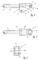
- the rigid jaw which is illustrated in Fig. 1, is as a whole referred to as 1 and has a body 2, which is provided with a shank 3, which serves to connect the rigid jaw 1 with a work cylinder, which is not illustrated.
- the rigid jaw 1 has an irregular long shape and is made of plate material, such as steel, having a thickness of for example 3 mm.
- the body 2 is extended like a nose 4 adapted to receive a gripping device 31, which is illustrated in Figs. 9 and 10, to retrieve one free end of the spring wire of a hose clamp of the type described in the introduction, however, it will be understood that the gripping device according to the invention with appropriately designed gripping devices can be used to clamp together other objects.
- the mentioned gripping device 31 may be fastened to the nose 4 by means of a screw or similar object, which is driven through the clamp fitting of the gripping device 31 as well as through the hole 5 of the nose 4.
- the shank 3 is similarly provided with holes 6 for securing the body 2 to the work cylinder.
- the body 2 has a longitudinal groove 7 extending along the upper side 10 of the body 2 and in parallel with the longitudinal direction of the shank 3, and thus also the longitudinal direction of the work cylinder in the mounted position of the gripping device.
- the inner side of the groove 7 located nearest to the upper side 10 forms a roller path or a link 8 for a roller head, which will be explained below.
- the upper side 10 and the roller path 8 define a beam 9.
- the body 2 also has a bore 11 for a shaft 12 for a movable jaw 13, which is illustrated in Figs. 2 and 3.
- the movable jaw 13 is constituted by two identical pieces of plate material 13a, 13b, such as steel, having a thickness of for example 2 mm, said two pieces 13a, 13b being joined at at least one end by means of a piece of plate 15, which is inserted between the said plate pieces, whereby the piece of plate 15 is of such thickness that the body 2 can be accommodated slidingly between the pieces of plate 13a, 13b.
- the two pieces of plate 13a, 13b consist of a first and a second prong 17, 18, which form an obtuse angle between them.
- the side of the prong 17 facing the angular space constitutes a roller path or link 17a, which will be explained below.
- a bore 14 for the shaft 12 referred to above is provided at the opposite end of the movable jaw 13.
- a pin 20 on the piece of plate 13a Approximately at the middle of the transition between the prongs 17, 18 is disposed a pin 20 on the piece of plate 13a, said pin serving the purpose of supporting a spring which is not shown in the drawing and the significance of which will be explained below.
- the said spring is preferably a torsional spring of the type wherein a spring wire is wound into several close-set coils, whereupon the free ends of the spring wire at the axially opposite ends of the coils extend radially from the coils.
- the structure of the spring thus corresponds to the hose clamps referred to above but has more coils than a hose clamp.
- the roller head 21 has on its front and underside a recess 28, whereby two identical tongues 30a and 30b appear holding the remaining part 29 of the roller head 21 together.
- the roller head 21 is at one end connected to a piston rod 22 in the work cylinder, which is not illustrated, and said connection may for instance consist in the piston rod 22 being formed as a threaded pin 23, which is screwed into a threaded hole provided in the roller head.
- roller head 21 has 23 a bore 24 for a shaft for an additional roller 26, and the roller head 21 has as an extension of the piston rod 22 another transverse bore 27 adapted to accommodate a shaft for a first roller 25, and the rollers 25, 26 are enclosed by the tongues 30a, 30b of the recess 28.
- the additional roller 26 has a diameter, which is slightly smaller than the width of the groove 7 in the body 2 of the rigid jaw 1.
- the movable jaw 13 is mounted rotatably on the rigid jaw 1, the mentioned shaft 12 being led through the bore 14 of the movable jaw 13 and the bore 11 of the rigid jaw 1, whereby the movable jaw 13 can rotate on the shaft 12 in relation to the rigid jaw 1.
- the mentioned spring is then mounted on the shaft 12, one free end of the spring wire being fastened in relation to the shank 3 of the rigid jaw 1, and the second free end being supported against the stop 20 of the movable jaw 13 in such a manner that the movable jaw 13 is swung into the position illustrated in Fig. 7 by means of the spring power.
- the roller head 21 is then screwed onto the threaded pin 23 of the piston rod 22, and the shank 3 is connected in a suitable manner to the work cylinder to the effect that the piston rod 22 extends parallel to the groove 7, and the two tongues 30a, 30b of the roller head 21 reach into and around the body 2 of the rigid jaw 1.
- the additional roller 26 is placed in the groove 7, and the shaft of the roller is mounted in the roller head 21 in the bore 24.
- the first roller 25 is mounted rotatably in the roller head 21 by means of the bore 27, whereby the diameter of the first roller 25 is so dimensioned that the roller 25 will not touch the upper side 10 of the body 2. It will be understood that the additional roller 26 can roll on the inner side 8 of the groove 7 in its mounted position.
- the mentioned gripping devices 31 are positioned on the noses 4 and 19 by means of their clamp fittings, and the gripping device is provided with guard plates for security reasons in order to prevent an operator from accidentally hurting himself by sticking a finger into the mechanism.
- guard plates can for instance be fastened by means of the shaft 12 and a screw or pin disposed in the hole 11a.
- the roller head 21 With the work cylinder in its inactivated position the roller head 21 will assume a withdrawn position, wherein the additional roller 26 is positioned at the extreme rear of the groove 7 at the end which is closest to the shank 3 of the rigid jaw 1. Consequently, the movable jaw 13, under the influence of power exerted by the spring, will move towards the position illustrated in Fig. 7, where the distance between the gripping devices 31 of the noses 4 and 19 is the maximum possible. It should be added that the movement of the movable jaw 13 in relation to the rigid jaw 1 can be reduced by means of the above mentioned guard plates, which are attached for security reasons, and it is also possible to adapt the distance between the gripping devices 31 in accordance with the size of the hose clamps, which are to be mounted by means of the gripping device.
- the gripping devices 31 of the noses 4 and 19 are placed on the two protruding ends of spring wire of the hose clamps, and the work cylinder is activated to the effect that the piston rod 22 is pushed out of the work cylinder towards the position illustrated in Fig. 8.
- the additional roller 26 will roll on the roller path or link, which is constituted by the inner side 8 of the groove 7, while the first roller 25 gets into contact with the roller path or link, which is constituted by the upper side 17a of the first prong 17 of the movable jaw 13, whereby the movable jaw 13 is pushed in the direction towards the rigid jaw 1.
- the mentioned gripping devices 31 are provided with a body 32, as illustrated in Figs. 9 and 10, with a flat pin 33 protruding from the underside of the body 32, said pin having a recess 35 at each side.
- the hose clamps consist of spring wire having a circular section
- the bodies 32 are formed with a cavity 34 on the surfaces facing one another to the effect that it is not possible for the ends of the spring wire to slide out of the gripping devices 31 as the ends of spring wire of a hose clamp are pressed together. If, on the other hand, the spring wire has a rectangular section, a groove will be provided in the bodies 32 instead of a cavity.
- the gripping devices 31 are secured to the noses 4, 19 by means of clamp fittings 36a, 36b, which reach in and around the pin 33 from each side of the noses, the clamp fittings with recesses 38a, 38b engaging in the recesses 35 of the pin 33.
- One clamp fitting 36a has a smooth bore 37a to accommodate a screw, which is not illustrated in the drawing, said screw being capable of penetrating the holes 5 and 16 of the noses 4, 19, whereas the second clamp fitting 36b has a interior threaded bore 37b for interaction with the screw.
- the movable jaw 13 may have a link, which can interact with the roller head 21 in such a manner that the movable jaw 13 is moved away from the rigid jaw 1 as the piston rod 22 is drawn into the work cylinder.
- the gripping device constitutes a unit, which can for example be secured to any work cylinder by means of a sleeve, which is not illustrated in the drawing.
- the sleeve may consist of a circular cylindrical bushing which has been slit up lengthwise, the slit having a width, which corresponds to the thickness of the shank 3. After the shank 3 has been inserted into the slit, the shank 3 is secured by means of screws, which are driven through the bushing and the holes 6 in the shank 3.
- the work cylinder is advantageously at the end from which the piston rod 22 protrudes provided with a concentric neck around the piston rod 22, on which the sleeve or the bushing can be mounted.
- the gripping device thus becomes rotatable in arbitrary angular positions on the axis of the work cylinder.
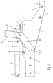
- FIG. 11 - 17 A second embodiment of a gripping device is illustrated in Figs. 11 - 17.
- this embodiment comprises in principle the same parts as described in the first embodiment, and consequently the references for the corresponding parts to the drawings are indicated by the same reference numbers with the addition of 100.
- first roller 125 as well as the additional roller 126 are positioned mutually rotatable on a common axis 139 in the roller head 121 and are movable in a direction, which is coincident with the axis 122a of the piston rod 122.
- the rigid jaw 101 also is provided with a groove 107 with the additional link 108 and a bore 111 for the axis 112 of the movable jaw 113, however the upper side 110 is not utilized as a link.
- the movable jaw 113 is different from the jaw 13 in that the link, contrary to what is indicated in first embodiment, is not divided into two prongs by an obtuse angle, one of the prongs 17a constituting the link; the link now consists of the entire part 117a of the jaw 113 facing the additional link 108 in the rigid jaw 101.
- the movable jaw 113 also has a triangular protrusion, 144 near the nose 119.
- This protrusion 144 is a security measure, which will close off a free area between the jaw 113 and the upper side 110 of the rigid jaw 101 in the wide open position of the gripping device. This will prevent an operator from unintentionally sticking a finger into this area before or during activation of the gripping device.
- the rigid jaw 101 is provided with two bores 111a, 111b for fastening of the above mentioned and not illustrated guard plates, said bores together with the bore 111 serving the purpose of accommodating suitable means, such as pins or screws, for the connection.
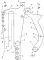
- the rigid jaw 101 is also provided with a number of holes 140 along its top edge for placement of a ring or a split-pin at option, which due to their protrusion crosswise in relation to the jaw 101 can reduce the move or opening movement of the movable jaw 113, when the work cylinder is not activated.
- the spring which must activate the movable jaw 113 may be seated on a pin or screw, which is placed in the bore 111a, whereby one end of the spring can actuate the pin 120, and the other end may bear against the edge of the rigid jaw 101.
- the pin 123 of the piston rod 122 which is formed as a threaded pin in the first embodiment, is in the second embodiment formed as a smooth, cylindrical pin 123 with a surrounding groove 141 around its mid-length.
- the roller head 121 is provided with a transverse bore 143 to accommodate a locking pin 142, which engage tangentially into the surrounding groove 141, whereby the roller head 121 is easily mounted on or demounted from the piston rod 122.
- the locking pin may be an elastic, resilient pin, allowing for removal of the roller head without removing the pin 142.
- roller head 121 By securing the roller head 121 to the piston rod 122 in the above described manner, the roller head is prevented from rotation on the piston rod 122 due to the pair of the first rollers 125 bearing against their respective part of the prongs 113a, 113b of the movable jaw 113.
- the roller head 121 With the work cylinder in its inactivated position, the roller head 121 will assume a withdrawn position, wherein the additional roller 126 will be positioned at the extreme rear of the groove 107 at the end, which is closest to the shank 103 of the rigid jaw 101.
- the movable jaw 113 therefore, will move towards the position illustrated in Fig. 16 under the influence of the power exerted by the spring, where the distance between the gripping devices 31 of the noses 104 and 119 is the longest possible.
- the move of the movable jaw 113 in relation to the rigid jaw 101 can be reduced by means of the above mentioned holes 140 and a pin or split-pin or, alternatively, guard plates, which are attached for security reasons, whereby it is also possible to adapt the distance between the gripping devices 31 in accordance with the sizes of the hose clamps, which are to be mounted by means of the gripping device.
- the gripping devices 31 of the noses 104 and 119 on the two protruding ends of spring wire are positioned, and the work cylinder is activated to the effect that the piston rod 122 is moved out of the work cylinder towards the position illustrated in Fig. 17.
- the additional roller 126 will roll on the roller path or link, which is constituted by the inner side 108 of the groove 107, while the first roller 125 gets into contact with the roller path or link, which is constituted by the upper side 117a of the prong 117 of the movable jaw 113, as a result of which the movable jaw 113 will be pressed in the direction towards the rigid jaw 101.
- the gripping device is adapted for a common working pressure of 4 bar for the work cylinder and a maximum opening distance of 75 mm between the free ends of an inactivated hose clamp.
Landscapes
- Engineering & Computer Science (AREA)
- General Engineering & Computer Science (AREA)
- Mechanical Engineering (AREA)
- Robotics (AREA)
- Manipulator (AREA)
- Wire Processing (AREA)
Claims (9)
- Greifer mit zwei Greiferbacken (1, 13; 101, 113), von denen die erste Greiferbacke (1; 101) fest und die zweite Greiferbacke (13; 113) auf einer in der ersten Greiferbacke (1; 101) vorhandenen Welle (12; 112) wie ein Hebel drehbar ist, einem Arbeitszylinder zur Bewegung der zweiten Backe (13; 113), dessen Kolbenstange (22; 122) zur Ausübung einer Kraft in einer Richtung, die im wesentlichen die Längsrichtung der Greiferbacken (1, 113; 101, 113) ist, ausgebildet ist, und einem Mechanismus zur Übertragung der Kraft der Kolbenstange (22; 122) auf die zweite Greiferbacke (13; 113) an einem Punkt, der zwischen der Welle (12; 112) und dem freien Ende oder der Nase (4, 19; 104, 119) der Greiferbacken (1 bzw. 13; 101 bzw. 113) liegt, wobei der Mechanismus aus einer ersten, an dem äußeren Ende der Kolbenstange (22; 122) angeordneten Rolle (25, 125) besteht, die zum Abrollen in einem Glied (17a; 117 a) der zweiten Greiferbacke (13; 113) ausgebildet ist, und einem zusätzlichen Glied (8; 108), das geradlinig und parallel zur Achse (22a; 122a) des Arbeitszylinders ausgerichtet ist, dadurch gekennzeichnet, daß die erste Rolle (25; 125) in einem Rollenkopf (21; 121) befestigt ist, der eine mit dem zusätzlichen Glied (8; 108) in der ersten Greiferbacke (1; 101) zusammenwirkende Zusatzrolle (26; 126) aufweist und daß eine Einrichtung zur Öffnung der Greiferbacken (1, 13; 101, 113) vorgesehen ist.
- Greifer nach Anspruch 1, dadurch gekennzeichnet, daß das zusätzliche Glied (8; 108) durch die Kante einer Ausnehmung (7; 107) in der ersten Greiferbacke gebildet ist, die versetzt zur Achse in der ersten Greiferbacke (1; 101) angeordnet ist.
- Greifer nach den Ansprüchen 1 bis 2, dadurch gekennzeichnet, daß die erste Greiferbacke (1; 101) aus einem Plattenmaterial gebildet ist.
- Greifer nach Anspruch 3, dadurch gekennzeichnet, daß die zweite Greiferbacke (13; 113) zwei Teile (13a, 13b; 113a, 113b) aufweist, die in einem relativen Abstand zueinander so angeordnet sind, daß die beiden Teile (13a, 13b; 113a, 113b) gleitend um die zugehörige Seite der ersten Greiferbacke (1; 101) greifen können.
- Greifer nach einem der vorhergehenden Ansprüche 1 bis 3, dadurch gekennzeichnet, daß die zweite Greiferbacke aus zwei Gabeln (17, 18) besteht, die zwischen sich einen stumpfen Winkel ausbilden und daß das Glied (17a) durch die Seite der Gabel (17) gebildet ist, die am weitesten entfernt von der dem Winkelraum und dem zusätzlichen Glied (8) gegenüberliegenden Achse angeordnet ist.
- Greifer nach einem der vorhergehenden Ansprüche 1 bis 5, dadurch gekennzeichnet, daß die erste Rolle (25) in der Richtung der Achse (22a) der Kolbenstange (22) angeordnet ist und daß die zusätzliche Rolle (26) näher an dem Arbeitszylinder und näher an der bewegbaren Greiferbacke (13) als die erste Rolle (25) angeordnet ist.
- Greifer nach einem der vorhergehenden Ansprüche 1 bis 3, dadurch gekennzeichnet, daß sich der Übergang von einer Gabel (118) zu der zweiten Gabel (117) in der zweiten Greiferbacke (113) in einer Kurve erstreckt und daß das Glied (117a) durch die dem zusätzlichen Glied (108) gegenüberliegenden Seite der zweiten Greiferbacke (113a, 113b) gebildet ist.
- Greifer nach Anspruch 7, dadurch gekennzeichnet, daß die erste Rolle (125) und die zusätzliche Rolle (126) drehbar auf der selben Welle (139) angeordnet sind, die sich quer zur Achse (122a) der Kolbenstange (122) erstreckt.
- Greifer nach Anspruch 1, dadurch gekennzeichnet, daß die Einrichtung zum Öffnen der Greiferbacken (1, 13; 101, 113) aus einer Druckfeder besteht.
Applications Claiming Priority (4)
| Application Number | Priority Date | Filing Date | Title |
|---|---|---|---|
| DK30/93 | 1993-01-12 | ||
| DK3093 | 1993-01-12 | ||
| DK003093A DK3093A (da) | 1993-01-12 | 1993-01-12 | Kraftbetjent gribeklo med to kæber |
| PCT/DK1993/000409 WO1994015759A1 (en) | 1993-01-12 | 1993-12-07 | Power-operated gripping device with two jaws |
Publications (2)
| Publication Number | Publication Date |
|---|---|
| EP0678067A1 EP0678067A1 (de) | 1995-10-25 |
| EP0678067B1 true EP0678067B1 (de) | 1998-02-25 |
Family
ID=8088957
Family Applications (1)
| Application Number | Title | Priority Date | Filing Date |
|---|---|---|---|
| EP94904137A Expired - Lifetime EP0678067B1 (de) | 1993-01-12 | 1993-12-07 | Motorangetriebener greifer mit zwei greiferbacken |
Country Status (8)
| Country | Link |
|---|---|
| US (1) | US5641190A (de) |
| EP (1) | EP0678067B1 (de) |
| JP (1) | JPH08505092A (de) |
| AU (1) | AU5831494A (de) |
| DE (1) | DE69317128T2 (de) |
| DK (1) | DK3093A (de) |
| ES (1) | ES2113086T3 (de) |
| WO (1) | WO1994015759A1 (de) |
Families Citing this family (10)
| Publication number | Priority date | Publication date | Assignee | Title |
|---|---|---|---|---|
| US5890754A (en) * | 1997-11-21 | 1999-04-06 | Murr; Wayne L. | Grapple claw attachment for a backhoe |
| US6065791A (en) * | 1998-06-01 | 2000-05-23 | Macdonald Dettwiler Space And Advanced Robotics Ltd. | Collet end effector |
| US6116118A (en) * | 1998-07-15 | 2000-09-12 | Wesch, Jr.; William E. | Gripping apparatus for power tongs and backup tools |
| RU2247021C1 (ru) * | 2003-08-29 | 2005-02-27 | Калининградский государственный технический университет | Устройство типа "рука" для передачи изделий |
| RU2419119C2 (ru) * | 2008-12-09 | 2011-05-20 | Федеральное государственное учреждение "Российский научный центр рентгенорадиологии" Министерства здравоохранения и социального развития Российской Федерации (ФГУ "РНЦРР" Минздравсоцразвития России) | Быстродействующая композиция без запаха для фиксирования рентгеновских фотоматериалов |
| EP2465651A1 (de) * | 2010-12-14 | 2012-06-20 | FFT EDAG Produktionssysteme GmbH & Co. KG | Vorrichtung zur Aufnahme und Handhabung eines Bauteils und Verfahren zum Herstellen einer solchen Vorrichtung |
| US9492929B1 (en) | 2015-11-04 | 2016-11-15 | Google Inc. | Flat gripper actuator |
| CN114102478A (zh) * | 2021-12-14 | 2022-03-01 | 中国科学院沈阳自动化研究所 | 一种可调四点夹持的绝缘子夹持机构 |
| CN114603588B (zh) * | 2022-04-11 | 2023-08-29 | 湘潭大学 | 一种陶瓷杯具夹持翻转机械手 |
| CN119017063B (zh) * | 2024-08-21 | 2025-11-11 | 珠海格力智能装备有限公司 | 滚轮组件装配机构 |
Family Cites Families (8)
| Publication number | Priority date | Publication date | Assignee | Title |
|---|---|---|---|---|
| US976052A (en) * | 1908-12-16 | 1910-11-15 | Robert F Devine | Mechanically-operated tongs. |
| US1900194A (en) * | 1931-11-09 | 1933-03-07 | Niemi Matti | Hoisting block |
| GB570961A (en) * | 1943-05-28 | 1945-07-31 | English Steel Corp Ltd | Improvements in or relating to grabs for lifting heavy articles |
| US2527922A (en) * | 1948-03-23 | 1950-10-31 | Albert R Falkner | Moving means for building blocks |
| US3013835A (en) * | 1959-04-01 | 1961-12-19 | Leland F Blatt | Power operated jaw assembly |
| DE2505627A1 (de) * | 1975-02-11 | 1976-08-19 | Gerhard Schuster | Servomotorisch betaetigte greifvorrichtung |
| DE3808822A1 (de) * | 1988-03-16 | 1989-09-28 | Siemens Ag | Hydraulisch gesteuertes greifwerkzeug |
| US5033785A (en) * | 1990-04-20 | 1991-07-23 | Woolley Jr William J | Clamp mechanism |
-
1993
- 1993-01-12 DK DK003093A patent/DK3093A/da not_active Application Discontinuation
- 1993-12-07 WO PCT/DK1993/000409 patent/WO1994015759A1/en not_active Ceased
- 1993-12-07 ES ES94904137T patent/ES2113086T3/es not_active Expired - Lifetime
- 1993-12-07 US US08/481,537 patent/US5641190A/en not_active Expired - Fee Related
- 1993-12-07 EP EP94904137A patent/EP0678067B1/de not_active Expired - Lifetime
- 1993-12-07 AU AU58314/94A patent/AU5831494A/en not_active Abandoned
- 1993-12-07 JP JP6515594A patent/JPH08505092A/ja active Pending
- 1993-12-07 DE DE69317128T patent/DE69317128T2/de not_active Expired - Fee Related
Also Published As
| Publication number | Publication date |
|---|---|
| US5641190A (en) | 1997-06-24 |
| DE69317128T2 (de) | 1998-10-08 |
| AU5831494A (en) | 1994-08-15 |
| EP0678067A1 (de) | 1995-10-25 |
| DK3093A (da) | 1994-07-13 |
| DK3093D0 (da) | 1993-01-12 |
| ES2113086T3 (es) | 1998-04-16 |
| DE69317128D1 (de) | 1998-04-02 |
| JPH08505092A (ja) | 1996-06-04 |
| WO1994015759A1 (en) | 1994-07-21 |
Similar Documents
| Publication | Publication Date | Title |
|---|---|---|
| EP0678067B1 (de) | Motorangetriebener greifer mit zwei greiferbacken | |
| CA1155465A (en) | Self-adjusting toggle clamps for factory fixtures and the like | |
| US5727899A (en) | Fulcrum clamp | |
| JPH0722790B2 (ja) | ポンチ、ダイスまたは類似のツール等の細長い部品を曲げプレスの取付板に固定する装置 | |
| US5837967A (en) | Burner holder for mechanized or automated arc welding or cutting torches, especially machine and/or robot torches | |
| US4989443A (en) | Crimping apparatus | |
| US4133519A (en) | Vise with selectable jaw faces | |
| US4648166A (en) | Claw extractor | |
| NO178240B (no) | Klemme til forbindelse av forskalingsplater | |
| KR20010093693A (ko) | 로드 그리퍼 | |
| EP1004410B1 (de) | Einstellbare Stoppers zur begrenzung des Öffnungswinkels eines Greifers | |
| KR20080089660A (ko) | 유압 구동식 프레스 장치 및 설비물의 프레스 방법 | |
| US2997903A (en) | Pliers with self-adjusting toggle means | |
| US20030019272A1 (en) | Hydraulic press brake tool holder | |
| US5527024A (en) | Toggle clamp with latch mechanism | |
| EP3993195A1 (de) | Greifwerkzeug | |
| US3425732A (en) | Gripping head with adjustable pivots for swinging jaws | |
| NZ260537A (en) | Hand screw clamp; means for quickly moving the tool into clamping position without rotating the threaded rods of the hand screw | |
| US6948708B2 (en) | Gripper provided with an adjustable sensor assembly | |
| US4569509A (en) | Vise, particularly a machine vise | |
| AU2010360812B2 (en) | Clamping tool and method of dismounting or mounting a jaw or a jaw support | |
| US4263705A (en) | Dowel pin puller | |
| US4854565A (en) | Clamping device | |
| ATE181978T1 (de) | Schnellwechselvorrichtung für erdbewegungsmaschine und dgl. | |
| EP2177320A1 (de) | Irreversible Kniehebelantriebsvorrichtung |
Legal Events
| Date | Code | Title | Description |
|---|---|---|---|
| PUAI | Public reference made under article 153(3) epc to a published international application that has entered the european phase |
Free format text: ORIGINAL CODE: 0009012 |
|
| 17P | Request for examination filed |
Effective date: 19950803 |
|
| AK | Designated contracting states |
Kind code of ref document: A1 Designated state(s): DE DK ES FR GB IT SE |
|
| GRAG | Despatch of communication of intention to grant |
Free format text: ORIGINAL CODE: EPIDOS AGRA |
|
| 17Q | First examination report despatched |
Effective date: 19970307 |
|
| GRAH | Despatch of communication of intention to grant a patent |
Free format text: ORIGINAL CODE: EPIDOS IGRA |
|
| GRAH | Despatch of communication of intention to grant a patent |
Free format text: ORIGINAL CODE: EPIDOS IGRA |
|
| GRAA | (expected) grant |
Free format text: ORIGINAL CODE: 0009210 |
|
| AK | Designated contracting states |
Kind code of ref document: B1 Designated state(s): DE DK ES FR GB IT SE |
|
| REF | Corresponds to: |
Ref document number: 69317128 Country of ref document: DE Date of ref document: 19980402 |
|
| REG | Reference to a national code |
Ref country code: ES Ref legal event code: FG2A Ref document number: 2113086 Country of ref document: ES Kind code of ref document: T3 |
|
| ITF | It: translation for a ep patent filed | ||
| PG25 | Lapsed in a contracting state [announced via postgrant information from national office to epo] |
Ref country code: SE Free format text: LAPSE BECAUSE OF FAILURE TO SUBMIT A TRANSLATION OF THE DESCRIPTION OR TO PAY THE FEE WITHIN THE PRESCRIBED TIME-LIMIT Effective date: 19980525 Ref country code: DK Free format text: LAPSE BECAUSE OF FAILURE TO SUBMIT A TRANSLATION OF THE DESCRIPTION OR TO PAY THE FEE WITHIN THE PRESCRIBED TIME-LIMIT Effective date: 19980525 |
|
| ET | Fr: translation filed | ||
| PGFP | Annual fee paid to national office [announced via postgrant information from national office to epo] |
Ref country code: GB Payment date: 19981125 Year of fee payment: 6 |
|
| PGFP | Annual fee paid to national office [announced via postgrant information from national office to epo] |
Ref country code: DE Payment date: 19981202 Year of fee payment: 6 |
|
| PGFP | Annual fee paid to national office [announced via postgrant information from national office to epo] |
Ref country code: ES Payment date: 19981210 Year of fee payment: 6 |
|
| PGFP | Annual fee paid to national office [announced via postgrant information from national office to epo] |
Ref country code: FR Payment date: 19981229 Year of fee payment: 6 |
|
| PLBE | No opposition filed within time limit |
Free format text: ORIGINAL CODE: 0009261 |
|
| STAA | Information on the status of an ep patent application or granted ep patent |
Free format text: STATUS: NO OPPOSITION FILED WITHIN TIME LIMIT |
|
| 26N | No opposition filed | ||
| PG25 | Lapsed in a contracting state [announced via postgrant information from national office to epo] |
Ref country code: GB Free format text: LAPSE BECAUSE OF NON-PAYMENT OF DUE FEES Effective date: 19991207 |
|
| GBPC | Gb: european patent ceased through non-payment of renewal fee |
Effective date: 19991207 |
|
| PG25 | Lapsed in a contracting state [announced via postgrant information from national office to epo] |
Ref country code: FR Free format text: LAPSE BECAUSE OF NON-PAYMENT OF DUE FEES Effective date: 20000831 |
|
| PG25 | Lapsed in a contracting state [announced via postgrant information from national office to epo] |
Ref country code: DE Free format text: LAPSE BECAUSE OF NON-PAYMENT OF DUE FEES Effective date: 20001003 |
|
| REG | Reference to a national code |
Ref country code: FR Ref legal event code: ST |
|
| PG25 | Lapsed in a contracting state [announced via postgrant information from national office to epo] |
Ref country code: ES Free format text: LAPSE BECAUSE OF NON-PAYMENT OF DUE FEES Effective date: 20001208 |
|
| REG | Reference to a national code |
Ref country code: ES Ref legal event code: FD2A Effective date: 20010113 |
|
| PG25 | Lapsed in a contracting state [announced via postgrant information from national office to epo] |
Ref country code: IT Free format text: LAPSE BECAUSE OF NON-PAYMENT OF DUE FEES;WARNING: LAPSES OF ITALIAN PATENTS WITH EFFECTIVE DATE BEFORE 2007 MAY HAVE OCCURRED AT ANY TIME BEFORE 2007. THE CORRECT EFFECTIVE DATE MAY BE DIFFERENT FROM THE ONE RECORDED. Effective date: 20051207 |