EP0678152B1 - Systeme pour la lubrification des points de graissage des cylindres de travail dans des machines a pistons de grande taille, principalement des moteurs diesel de navires - Google Patents
Systeme pour la lubrification des points de graissage des cylindres de travail dans des machines a pistons de grande taille, principalement des moteurs diesel de navires Download PDFInfo
- Publication number
- EP0678152B1 EP0678152B1 EP92910956A EP92910956A EP0678152B1 EP 0678152 B1 EP0678152 B1 EP 0678152B1 EP 92910956 A EP92910956 A EP 92910956A EP 92910956 A EP92910956 A EP 92910956A EP 0678152 B1 EP0678152 B1 EP 0678152B1
- Authority
- EP
- European Patent Office
- Prior art keywords
- oil
- piston
- lubrication
- dosing
- pressure
- Prior art date
- Legal status (The legal status is an assumption and is not a legal conclusion. Google has not performed a legal analysis and makes no representation as to the accuracy of the status listed.)
- Expired - Lifetime
Links
- 238000005461 lubrication Methods 0.000 title claims abstract description 29
- 230000001050 lubricating effect Effects 0.000 claims description 6
- 238000009434 installation Methods 0.000 claims description 5
- 230000008859 change Effects 0.000 claims description 4
- 239000013589 supplement Substances 0.000 claims 1
- 239000003921 oil Substances 0.000 description 64
- 238000002347 injection Methods 0.000 description 8
- 239000007924 injection Substances 0.000 description 8
- 230000000694 effects Effects 0.000 description 5
- 239000010687 lubricating oil Substances 0.000 description 5
- 230000004913 activation Effects 0.000 description 3
- 230000006978 adaptation Effects 0.000 description 2
- 230000008901 benefit Effects 0.000 description 2
- 238000001514 detection method Methods 0.000 description 2
- 230000009467 reduction Effects 0.000 description 2
- 238000007790 scraping Methods 0.000 description 2
- 230000003213 activating effect Effects 0.000 description 1
- 230000001154 acute effect Effects 0.000 description 1
- 238000000034 method Methods 0.000 description 1
- 230000008569 process Effects 0.000 description 1
- 239000002699 waste material Substances 0.000 description 1
Images
Classifications
-
- F—MECHANICAL ENGINEERING; LIGHTING; HEATING; WEAPONS; BLASTING
- F01—MACHINES OR ENGINES IN GENERAL; ENGINE PLANTS IN GENERAL; STEAM ENGINES
- F01M—LUBRICATING OF MACHINES OR ENGINES IN GENERAL; LUBRICATING INTERNAL COMBUSTION ENGINES; CRANKCASE VENTILATING
- F01M1/00—Pressure lubrication
- F01M1/16—Controlling lubricant pressure or quantity
-
- F—MECHANICAL ENGINEERING; LIGHTING; HEATING; WEAPONS; BLASTING
- F01—MACHINES OR ENGINES IN GENERAL; ENGINE PLANTS IN GENERAL; STEAM ENGINES
- F01M—LUBRICATING OF MACHINES OR ENGINES IN GENERAL; LUBRICATING INTERNAL COMBUSTION ENGINES; CRANKCASE VENTILATING
- F01M1/00—Pressure lubrication
- F01M1/08—Lubricating systems characterised by the provision therein of lubricant jetting means
- F01M2001/083—Lubricating systems characterised by the provision therein of lubricant jetting means for lubricating cylinders
-
- F—MECHANICAL ENGINEERING; LIGHTING; HEATING; WEAPONS; BLASTING
- F02—COMBUSTION ENGINES; HOT-GAS OR COMBUSTION-PRODUCT ENGINE PLANTS
- F02B—INTERNAL-COMBUSTION PISTON ENGINES; COMBUSTION ENGINES IN GENERAL
- F02B3/00—Engines characterised by air compression and subsequent fuel addition
- F02B3/06—Engines characterised by air compression and subsequent fuel addition with compression ignition
Definitions
- the present invention relates to a lubrication system for dosing oil to one or more lubrication points in large piston engine cylinders, primarily in naval engines, and more specifically in the manner indicated in the introductory clause of claim 1.
- central lubrication devices each of which operates in connection with the lubrication points of one or more cylinders by pressing out oil portions through respective connecting pipes to the various oiling points at relevant moments of time.
- These moments or short time intervals are precisely defined in relation to the movement of the engine piston in the cylinder, the oil supply through a considered lubrication point ideally occurring exactly at the brief time lapse where a set of associated piston rings on the piston passes the concerned oiling point.
- the lubrication of the cylinder wall becomes ineffective, if the oil is supplied at moments where the cylinder wall is not being swept by the piston rings or special by oil scraping rings, respectively, exactly adjacent to the individual concerned lubrication point.
- the central lubrication devices are controlled in synchronism with the revolutions of the engine crankshaft and it is therefore relatively easy to adjust the device for supplying the various portions of lubricating oil to the various oiling points at reasonably relevant moments of time.
- a pressure oil accumulator may advantageously be used which is placed in immediate proximity to the inlet of the individual dosing unit, such that it is possible by the relatively sudden opening of the valve to maintain the desired high supply pressure of the oil in an extra safe manner.
- a certain elasticity occurs in the longer supply pipe for the pressure oil, also because on average there must be correspondence between the oil supply from the oil pump and the inlet of oil at the oiling point.
- a primary aim is a lubrication with a determined oil quantity per round, even though it may be relevant to regulate this quantity, such as it is basically attempted by the use of the central lubricating devices, in which stroke adjustable piston pumps are provided for pressing out the oil to the individual oiling points or groups thereof.
- this principle may very well be applied without the said associated problems by a partial implementation of the known suggestion, viz. by the lubrication system being embodied as indicated in the characterizing clause of claim 1, i.e. in principle by effecting both the volumetric dosing and the time control by means of the locally placed dosing units.
- the dosing unit or units being designed for volumetrically determined intake and outlet of the oil portions, the latter will or may be correct regardless of the operating speed of the piston engine or the viscosity of the oil, and by the very fact of the dosing being controllable, an adaptation may easily be effectuated according to occurring parameter changes which may make such an adaptation desirable, e.g. a change of the oil viscosity.
- the dosing units may be embodied in a very simple manner, e.g.
- the pressurized oil may be used for filling the cylinder by its own pressure until the piston abuts the axial stop, and thereafter the pressurized oil may be used for emptying the measured-out oil volume to the oiling point, viz. in being connected to the cylinder space at the opposite side of the piston.
- the dosing will require no further operation energy, except for the valve control itself.
- the dosing units may be single-acting, with a working space which may be connected alternately to the inlet for pressurized oil, for filling of the working space, and to the oiling point for supplying oil thereto, and with a pressure champer, which is correspondingly alternately connectable to a return pipe and to the pressure oil inlet respectively, such that the piston may press out the oil in this champer during the filling of the working space and be pressed forwards by the pressurized oil for pressing out the measured-out oil volume.
- a differential piston one part of which operates in a pressure chamber of increased diameter relative the working chamber, the space between this piston and the narrower working piston simply being permanently connected to said return pipe.
- the ordinary oil pressure may be used for providing a locally strongly increased oiling pressure at the dosing unit.
- the dosing units may also be double-acting, the cylinder chambers on the two sides of the piston being connectable alternately to the pressure oil inlet and the oiling point, respectively.
- the said return pipe may be altogether dispensable. Also by this arrangement there may be made use of a differential piston, in double, even though a return pipe must then be used.
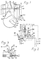
- the cylinder shown in Fig. 1 has a cylinder liner 2 in which is provided a number of oiling holes 4, each of which is connected through a short pipe 6 to an associated injection respectively dosing unit 8.
- These units 8 are supplied with pressure oil through supply pipes 10 from a high-pressure pump 12 suctioning from a tank 14, to which is conducted a supply pipe 16 from a non-illustrated supply of lubricating oil, and a return pipe 18 from the units 8.
- Electrical control cables are indicated in dotted lines 20 from a control unit 22 to the individual units 8.
- the cylinder is provided with a piston 24, which via a piston rod 26 and a connecting rod 28 is connected to a crank 30,32 in a crank housing.
- a pair of piston or scraping rings 36 are placed near the top of the piston, and the ideal is that the lubricating oil from each oiling point 4 be injected just when this pair of rings passes the concerned oiling point, which means in practice that the injection of the lubricating oil should take place by high power during a very short lapse of time.
- each unit has a piston cylinder 40 with an outlet pipe 42 connected to a switch-over valve 44, which, controlled by an actuator unit 46, may be switched to connection with the injector pipe 6 and the oil supply pipe 10, respectively.
- the short pipe 6 is provided with a check-valve 7, preventing backwards flow of oil from the oiling hole 4.
- a piston 48 is mounted in the cylinder 40, and at its rear end the cylinder 40 is connected to a pipe conduit 50 leading to a switch-over unit 52 which is co-operated with the switch-over valve 44 in such a manner that the conduit 50 will be connected to the oil pressure pipe 10 when the outlet pipe 42 is connected to the injector pipe 6, while the pipe conduit 50 will be connected to the return pipe 18, when the outlet pipe 42 is connected to the pressure pipe 10.
- a stopper rod 54 projecting in through the upper rear end of the cylinder 40, which rod determines the maximally retracted position of the piston 48.
- this rod is secured against being rotated, and at its outer end it is in thread engagement with a stationarily fixed nut 56, which may be caused to rotate by a step motor 58 controlled from the control unit 22 in Fig. 1.
- a pressure transducer 60 may be placed in connection with the pipe 50, and optionally a corresponding transducer may be placed at the outlet 42,6 from the cylinder 40. These transducers may be connected to the control unit 22 e.g. for control and supervision purposes.
- the valve unit 44,52 In a preparatory phase the valve unit 44,52 is held in such a position in which the pipe 42 is connected to the pressure pipe 10 at the lower end of the cylinder 40, while at the upper end of the cylinder the pipe 50 is connected to the return pipe 18.
- pressurized oil will be injected into the lower end of the cylinder 40, such that the piston 48 is pressed upwards until it abuts the end of the stopper rod 54.
- the control unit 22 receives a plurality of different, relevant informations from various sensors in the system, such that the oil volume injected into the cylinder 40 will be appropriate for the subsequent supply of this volume through the oiling hole 4.
- the control unit 22 will provide current to the activating unit 46 for switching the valve unit 44,52.
- this piston is thrust powerfully downwards so as to eject the oil portion in front of the piston with great force in front of the piston for delivery through the oiling hole 4 during a very brief time lapse, thus with an abrupt finishing of both the beginning and the ending phase of the opening period.
- the unit 46 may be activated for resetting the switch valve 44,52, such that once more a new oil portion may be filled into the upper space of the cylinder 40.
- the filling will once more take place until the piston 48 abuts the stopper rod 54, the position of which may be currently adjusted by the control of the step motor 58 from the control unit 22, based on detections from different relevant sensors.
- a detected reduced motor load may condition a reduced oil dosage, while at the same time, as a primary function, it may be desirable to increase the dosing, if a sudden change in the motor load has just occurred, also including a reduction hereof, as such changes may otherwise cause an increased cylinder wear.
- the increased dosing should be maintained through a certain period of time after the occurred change, e.g. 15-30 minutes, which may easily be adjusted by means of a timer and optional sensors connected thereto for detection of conditions which may influence the optimal length of the period through which the increased lubrication is maintained.
- control unit 22 may convey the final result to the motor 58 or corresponding adjustment means, respectively, and to the activation unit 46,54 for the individual dosing units, regardless of the nature of this activation.
- a pressure oil accumulator is placed in the inlet conduit 10 immediately in front of each of the switch-over units 52 or in front of various local groups of dosing units, e.g. merely in the shape of a slightly resilient container of a somewhat larger diameter that the inlet pipe 10, such that the required amount of oil may very quickly flow to the the rear end of the cylinder 40 by the activation of the valve 44,52, not requiring the inlet pipe 10 to have any particularly large diameter.
- the pressure oil in the inlet 10 is stille used for pressing forward the piston 48 for dosing oil from the measuring chamber in front of the piston, but here the unit is designed as a double-acting unit.
- the shown change-over valve 62 sends pressure oil from the pipe 10 into the right hand end of the cylinder 40 through a pipe 64, while the left hand end of the cylinder is connected to a parallel change-over valve 66, position I, through a pipe 68.
- This valve is permanently connected to the concerned lubrication point or points through a short pipe 70.
- the pipes 64 and 68 are connected to the I-positions of the respective change-over valves 62 and 66, but moreover, they are connected through pipe extensions 74 and 76 to the II-positions of the respective opposite change-over valves.
- the cylinder 40 is entirely oil-filled at both sides of the piston 48.
- the piston 48 With the pair 62,66 of change-over valves in the shown position II, the piston 48 will be in the illustrated end position to the right.
- the valve 62,66 is changed into position I. Pressure oil from the pipe 10 will then flow to the right end of the cylinder through the valve 62 and the pipe 64.
- the piston 48 is thereby displaced to the left and presses out oil through the pipe 68 to the lubricating pipe 70. This pressing out abruptly stops, when the piston 48 abuts the left end of the cylinder.
- valve 62,66 is again shifted to position II. Pressure oil from the pipe 10 will then flow to the left end of the cylinder through the valve 66 and the pipe 68.
- the piston 48 is thereby displaced to the right and forces out the oil portion which was at the right side of the piston through the pipe 64, the valve 62 and the pipe 74 to the lubrication pipe 70. This forcing abruptly stops, when the piston 48 abuts the stopper rod 54.
- connection conduits 6 between the dosing units and the motor cylinder may be kept quite short, such that from a flow-technical point of view they may appear entirely rigid and thus without any noticeable accumulator effect, as would be undesired here.
- each dosing unit may be arranged so as to operate in connection with several lubrication points simultaneously, inasfar as normally several lubrication points are placed in the same cross section of the engine cylinder. Furthermore, an individual dosing unit will be able to operate in connection with several lubrication points at different moments, viz. through a suitable shifter equipment.
- the dosing units do not necessarily have to be placed immediately next to the oiling points. Already the possibility of positioning right next to the cylinder area will entail a noticeable reduction of the length of the lubrication pipes relative to current practice, and optionally the units may then be placed in local groups.
- the pressure oil per se which is used for producing the injection force, but the invention is not limited hereto.
- a compressed-air system may be used, e.g. in connection with a differential piston arrangement for amplifyring the pressure exerted on the dosing piston.
- a strong electromagnet may be used for projecting the dosing piston against a suitable spring effect. In such cases the inlet oil does not have to be conveyed at any particularly high pressure.
Landscapes
- Engineering & Computer Science (AREA)
- Mechanical Engineering (AREA)
- General Engineering & Computer Science (AREA)
- Lubrication Of Internal Combustion Engines (AREA)
Abstract
Claims (6)
- Système de lubrification pour le dosage successif d'huile en un ou plusieurs points de lubrification dans des grands cylindres de moteur à pistons, particulièrement dans des moteurs marins, laquelle installation comprend une pompe à huile (12) et une unité de dosage (8) reliée au côté refoulement de celle-ci, éventuellement plusieurs telles unités (8), qui sont placées de préférence proches des points de lubrification concernés, chaque unité de dosage (8) étant adaptée de façon à véhiculer l'huile sous pression en une quantité bien contrôlée souhaitée à chaque point de lubrification relié par commande à partir d'une unité de commande (22) pendant de courtes phases prédéterminées du cycle de fonctionnement du moteur à pistons, éventuellement avec des compléments d'huile à partir d'un accumulateur d'huile à proximité de l'unité de dosage,
caractérisé en ce que l'unité de dosage (8) ou chacune de ces unités est prévue comme une unité de mesure volumétrique, à partir de laquelle l'unité de commande (22) est apte à fonctionner pour le changement commandé du volume de mesure, et qui est conçue et agencée de telle sorte que, par une opération commandé subséquente, la quantité mesurée d'huile peut être évacuée vers le ou les points de lubrification sous l'influence d'une force de pression appliquée localement sur ladite quantité d'huile, par exemple la pression d'huile dans le conduit d'admission d'huile (10) lui-même, et un accumulateur d'huile éventuellement disposé dans celui-ci. - Système selon la revendication 1,
caractérisé en ce que l'unité de dosage (8) est munie d'un cylindre de mesure (40) dans lequel est monté un piston (48) ou un embout de piston, dont le déplacement est limité, dans au moins un sens par une butée d'arrêt (54), dont la position est réglable depuis l'extérieur par l'intermédiaire d'un mécanisme à déplacement tel qu'un moteur pas à pas (58) commandable par l'intermédiaire de l'unité de commande (22). - Système selon la revendication 1,
caractérisé en ce que l'unité de dosage (8) est reliée à une installation d'huile sous pression par des valves de commande individuelles associées (44,52), qui, à partir de l'unité de commande (22), sont déplaçables entre une position d'attente dans laquelle l'huile sous pression peut s'écouler vers une chambre de mesure dans les unités individuelles pour remplir cette chambre dans le laps de temps entre les distributions successives, et une position de lubrification dans laquelle l'huile sous pression est utilisée comme moyen pour pousser l'huile dans la chambre de mesure vers les points de graissage respectifs. - Système selon la revendication 2,
caractérisé en ce que chacune des extrémités opposées du cylindre de mesure est en liaison par conduit avec un bloc de valves de commutation, à travers lesquels blocs, les chambres de cylindre opposées respectives sur les côtés opposés du piston (48) ou de l'embout de piston, sont alternativement reliées à une entrée d'huile sous pression et à une liaison de sortie (42) au point ou aux points de lubrification, respectivement. - Système selon la revendication 1,
caractérisé en ce que l'unité de commande (22) pour la détermination en cours du volume de distribution est du type qui est capable de déterminer le besoin de lubrification à partir d'une pluralité de paramètres mesurés dans le système de fonctionnement. - Système selon la revendication 1,
dans lequel la source commandable de la pression appliquée localement est un électro-aimant puissant capable d'actionner un piston pour pousser la quantité d'huile mesurée vers l'extérieur.
Applications Claiming Priority (3)
| Application Number | Priority Date | Filing Date | Title |
|---|---|---|---|
| DK983/91 | 1991-05-24 | ||
| DK98391A DK98391D0 (da) | 1991-05-24 | 1991-05-24 | Smoeresystem til successive doseringer af olie til smoeresteder i store stempelmaskinecylindre |
| PCT/DK1992/000165 WO1992020909A1 (fr) | 1991-05-24 | 1992-05-22 | Systeme pour la lubrification des points de graissage des cylindres de travail dans des machines a pistons de grande taille, principalement des moteurs diesel de navires |
Publications (2)
| Publication Number | Publication Date |
|---|---|
| EP0678152A1 EP0678152A1 (fr) | 1995-10-25 |
| EP0678152B1 true EP0678152B1 (fr) | 1997-08-13 |
Family
ID=8099701
Family Applications (1)
| Application Number | Title | Priority Date | Filing Date |
|---|---|---|---|
| EP92910956A Expired - Lifetime EP0678152B1 (fr) | 1991-05-24 | 1992-05-22 | Systeme pour la lubrification des points de graissage des cylindres de travail dans des machines a pistons de grande taille, principalement des moteurs diesel de navires |
Country Status (8)
| Country | Link |
|---|---|
| EP (1) | EP0678152B1 (fr) |
| JP (1) | JP3485319B2 (fr) |
| KR (1) | KR100251573B1 (fr) |
| DE (1) | DE69221642T2 (fr) |
| DK (2) | DK98391D0 (fr) |
| ES (1) | ES2106869T3 (fr) |
| PL (1) | PL171160B1 (fr) |
| WO (1) | WO1992020909A1 (fr) |
Cited By (3)
| Publication number | Priority date | Publication date | Assignee | Title |
|---|---|---|---|---|
| CN109690038A (zh) * | 2016-08-05 | 2019-04-26 | 汉斯延森注油器公司 | 用于大型低速运行内燃机和大型低速运行二冲程内燃机的汽缸的润滑安全系统 |
| US10627047B2 (en) | 2014-04-11 | 2020-04-21 | Alfa Laval Corporate Ab | Lubrication control system |
| US12269729B2 (en) | 2023-01-27 | 2025-04-08 | Vgp Ipco Llc | Reusable or refillable container for dispensing motor oil |
Families Citing this family (15)
| Publication number | Priority date | Publication date | Assignee | Title |
|---|---|---|---|---|
| JPH0754628A (ja) * | 1993-08-09 | 1995-02-28 | Yamaha Motor Co Ltd | 筒内燃料噴射式2サイクルエンジンの潤滑装置 |
| CA2350105A1 (fr) * | 1998-11-05 | 2000-05-18 | Hans Jensen Lubricators A/S | Systeme de lubrification pour moteurs diesel de grande taille |
| JP4685329B2 (ja) * | 2000-10-24 | 2011-05-18 | ハンス イエンセン ルブリカトーズ アクティーゼルスカブ | 分配装置 |
| DK200201605A (da) * | 2002-10-22 | 2004-04-23 | Hans Jensen Lubricators As | Ventil til montering i cyllindervæg |
| DK176742B1 (da) * | 2004-06-30 | 2009-06-02 | Hans Jensen Lubricators As | Fremgangsmåde og apparat til smöring af cylinderfladerne i store dieselmotorer |
| DK176366B1 (da) * | 2005-11-21 | 2007-10-01 | Hans Jensen Lubricators As | Smöreapparat til et doseringssystem for cylindersmöreolie samt fremgangsmåde til dosering af cylindersmöreolie |
| KR20090089789A (ko) * | 2008-02-19 | 2009-08-24 | 베르트질레 슈바이츠 악티엔게젤샤프트 | 실린더 윤활용 장치 |
| DK2177720T3 (da) * | 2008-10-16 | 2014-06-30 | Wärtsilä Schweiz AG | Stor dieselmotor |
| DK177746B1 (da) | 2009-06-23 | 2014-05-26 | Hans Jensen Lubricators As | Fremgangsmåde til cylindersmøring af store dieselmotorer såsom skibsmotorer |
| DK178033B1 (da) * | 2010-06-04 | 2015-03-30 | Hans Jensen Lubricators As | Hydraulisk system, fortrinsvis et centralsmøresystem til cylindersmøring |
| EP2484875B1 (fr) * | 2011-02-04 | 2013-11-27 | Wärtsilä Schweiz AG | Dispositif de lubrification de cylindre |
| KR101158837B1 (ko) * | 2011-12-05 | 2012-06-27 | 주식회사 한성정공 | 윤활 급유 펌프 |
| KR101506313B1 (ko) * | 2012-05-15 | 2015-03-26 | 맨 디젤 앤드 터보 필리얼 아프 맨 디젤 앤드 터보 에스이 티스크랜드 | 실린더 윤활 장치 |
| CN103527282B (zh) * | 2012-07-04 | 2017-06-30 | 瓦锡兰瑞士公司 | 润滑系统、润滑剂注入元件、内燃发动机以及润滑方法 |
| DK179945B1 (en) * | 2017-12-13 | 2019-10-21 | Hans Jensen Lubricators A/S | A large slow-running two-stroke engine and a method of lubricating it and a controller for such engine and method |
Family Cites Families (4)
| Publication number | Priority date | Publication date | Assignee | Title |
|---|---|---|---|---|
| DK81275C (da) * | 1954-04-28 | 1956-07-02 | Burmeister & Wains Mot Mask | Cylindersmøresystem ved forbrændingsmotorer. |
| SE445672B (sv) * | 1980-09-29 | 1986-07-07 | Bohlin E Ab | Anordning for portionsvis utstotande av ett emne, foretredesvis smorjfett |
| GR75371B (fr) * | 1980-10-04 | 1984-07-13 | British Petroleum Co | |
| JPH01244109A (ja) * | 1988-03-25 | 1989-09-28 | Mitsubishi Heavy Ind Ltd | 内燃機関のシリンダ注油装置 |
-
1991
- 1991-05-24 DK DK98391A patent/DK98391D0/da not_active Application Discontinuation
-
1992
- 1992-05-22 PL PL92301420A patent/PL171160B1/pl unknown
- 1992-05-22 EP EP92910956A patent/EP0678152B1/fr not_active Expired - Lifetime
- 1992-05-22 JP JP50977892A patent/JP3485319B2/ja not_active Expired - Lifetime
- 1992-05-22 DE DE69221642T patent/DE69221642T2/de not_active Expired - Lifetime
- 1992-05-22 WO PCT/DK1992/000165 patent/WO1992020909A1/fr not_active Ceased
- 1992-05-22 KR KR1019930703570A patent/KR100251573B1/ko not_active Expired - Lifetime
- 1992-05-22 DK DK92910956T patent/DK0678152T3/da active
- 1992-05-22 ES ES92910956T patent/ES2106869T3/es not_active Expired - Lifetime
Cited By (4)
| Publication number | Priority date | Publication date | Assignee | Title |
|---|---|---|---|---|
| US10627047B2 (en) | 2014-04-11 | 2020-04-21 | Alfa Laval Corporate Ab | Lubrication control system |
| CN109690038A (zh) * | 2016-08-05 | 2019-04-26 | 汉斯延森注油器公司 | 用于大型低速运行内燃机和大型低速运行二冲程内燃机的汽缸的润滑安全系统 |
| CN109690038B (zh) * | 2016-08-05 | 2021-02-09 | 汉斯延森注油器公司 | 用于大型低速运行内燃机的汽缸的润滑安全系统 |
| US12269729B2 (en) | 2023-01-27 | 2025-04-08 | Vgp Ipco Llc | Reusable or refillable container for dispensing motor oil |
Also Published As
| Publication number | Publication date |
|---|---|
| PL171160B1 (en) | 1997-03-28 |
| KR100251573B1 (ko) | 2000-04-15 |
| DE69221642T2 (de) | 1998-03-12 |
| JPH06510349A (ja) | 1994-11-17 |
| WO1992020909A1 (fr) | 1992-11-26 |
| JP3485319B2 (ja) | 2004-01-13 |
| DK98391D0 (da) | 1991-05-24 |
| DE69221642D1 (de) | 1997-09-18 |
| DK0678152T3 (da) | 1998-03-30 |
| EP0678152A1 (fr) | 1995-10-25 |
| ES2106869T3 (es) | 1997-11-16 |
Similar Documents
| Publication | Publication Date | Title |
|---|---|---|
| EP0678152B1 (fr) | Systeme pour la lubrification des points de graissage des cylindres de travail dans des machines a pistons de grande taille, principalement des moteurs diesel de navires | |
| US5388965A (en) | Sludge pump with monitoring system | |
| US5458470A (en) | Pumping apparatus | |
| RU2127829C1 (ru) | Шламовый насос с нагнетательными цилиндрами, в частности, двухцилиндровый бетононасос | |
| DK173288B1 (da) | Cylindersmøreenhed til en flercylindret forbrændingsmotor, og fremgangsmåde til styring af leveringsmængden fra en cylinder | |
| CN202023797U (zh) | 泵送机构及其脉冲振动吸收装置、混凝土泵送机械 | |
| US9358675B2 (en) | Lubricating pump with double-acting drive piston | |
| US5209649A (en) | Control system for a two-cylinder thick matter pump | |
| US3621865A (en) | Fluid pressure-operated pumps | |
| US3317002A (en) | Fluid distributing system | |
| US4411601A (en) | Pump for metering two distinct fluids | |
| US4479758A (en) | Piston filler | |
| CN1068406C (zh) | 舰用柴油机上大活塞机内用于活塞点润滑的润滑系统 | |
| DK179521B1 (en) | A large slow-running two-stroke engine, a method of lubricating it, and an injector with a step-wise hydraulic pumping system for such engine and method | |
| RU2489577C2 (ru) | Устройство для смазывания цилиндров и большой дизельный двигатель, содержащий такое устройство | |
| CA2299490A1 (fr) | Distributeur de lubrifiant | |
| RU2084348C1 (ru) | Гидравлический пресс | |
| CN217712832U (zh) | 一种可精密控制的气动切换式气液增压泵 | |
| KR20010070284A (ko) | 모터 | |
| SU533761A1 (ru) | Система управлени гидроприводом | |
| SU983375A1 (ru) | Система смазки | |
| RU2364706C1 (ru) | Способ беспрерывной дозированной перекачки жидкого химреагента и установка для его осуществления | |
| SU367288A1 (ru) | Гидропривод шагового перемещения | |
| EP0838589A2 (fr) | Méthode pour la compensation automatique de fuites de fluide hydraulique, circuit de compensation de fuites et dispositif à double piston comportant un tel circuit | |
| SU1414498A1 (ru) | Механизм прессовани "Мультдубль" машины лить под давлением |
Legal Events
| Date | Code | Title | Description |
|---|---|---|---|
| PUAI | Public reference made under article 153(3) epc to a published international application that has entered the european phase |
Free format text: ORIGINAL CODE: 0009012 |
|
| 17P | Request for examination filed |
Effective date: 19931221 |
|
| AK | Designated contracting states |
Kind code of ref document: A1 Designated state(s): CH DE DK ES FR IT LI |
|
| GRAG | Despatch of communication of intention to grant |
Free format text: ORIGINAL CODE: EPIDOS AGRA |
|
| 17Q | First examination report despatched |
Effective date: 19960312 |
|
| GRAH | Despatch of communication of intention to grant a patent |
Free format text: ORIGINAL CODE: EPIDOS IGRA |
|
| GRAH | Despatch of communication of intention to grant a patent |
Free format text: ORIGINAL CODE: EPIDOS IGRA |
|
| GRAA | (expected) grant |
Free format text: ORIGINAL CODE: 0009210 |
|
| AK | Designated contracting states |
Kind code of ref document: B1 Designated state(s): CH DE DK ES FR IT LI |
|
| REG | Reference to a national code |
Ref country code: CH Ref legal event code: EP |
|
| REF | Corresponds to: |
Ref document number: 69221642 Country of ref document: DE Date of ref document: 19970918 |
|
| REG | Reference to a national code |
Ref country code: CH Ref legal event code: NV Representative=s name: TROESCH SCHEIDEGGER WERNER AG |
|
| ITF | It: translation for a ep patent filed | ||
| REG | Reference to a national code |
Ref country code: ES Ref legal event code: FG2A Ref document number: 2106869 Country of ref document: ES Kind code of ref document: T3 |
|
| ET | Fr: translation filed | ||
| REG | Reference to a national code |
Ref country code: DK Ref legal event code: T3 |
|
| PLBE | No opposition filed within time limit |
Free format text: ORIGINAL CODE: 0009261 |
|
| STAA | Information on the status of an ep patent application or granted ep patent |
Free format text: STATUS: NO OPPOSITION FILED WITHIN TIME LIMIT |
|
| 26N | No opposition filed | ||
| PGFP | Annual fee paid to national office [announced via postgrant information from national office to epo] |
Ref country code: ES Payment date: 20020510 Year of fee payment: 11 |
|
| PGFP | Annual fee paid to national office [announced via postgrant information from national office to epo] |
Ref country code: FR Payment date: 20020523 Year of fee payment: 11 |
|
| PG25 | Lapsed in a contracting state [announced via postgrant information from national office to epo] |
Ref country code: ES Free format text: LAPSE BECAUSE OF NON-PAYMENT OF DUE FEES Effective date: 20030523 |
|
| PG25 | Lapsed in a contracting state [announced via postgrant information from national office to epo] |
Ref country code: FR Free format text: LAPSE BECAUSE OF NON-PAYMENT OF DUE FEES Effective date: 20040130 |
|
| REG | Reference to a national code |
Ref country code: FR Ref legal event code: ST |
|
| REG | Reference to a national code |
Ref country code: ES Ref legal event code: FD2A Effective date: 20030523 |
|
| PG25 | Lapsed in a contracting state [announced via postgrant information from national office to epo] |
Ref country code: IT Free format text: LAPSE BECAUSE OF NON-PAYMENT OF DUE FEES;WARNING: LAPSES OF ITALIAN PATENTS WITH EFFECTIVE DATE BEFORE 2007 MAY HAVE OCCURRED AT ANY TIME BEFORE 2007. THE CORRECT EFFECTIVE DATE MAY BE DIFFERENT FROM THE ONE RECORDED. Effective date: 20050522 |
|
| PGFP | Annual fee paid to national office [announced via postgrant information from national office to epo] |
Ref country code: CH Payment date: 20110510 Year of fee payment: 20 |
|
| PGFP | Annual fee paid to national office [announced via postgrant information from national office to epo] |
Ref country code: DK Payment date: 20110530 Year of fee payment: 20 |
|
| PGFP | Annual fee paid to national office [announced via postgrant information from national office to epo] |
Ref country code: DE Payment date: 20110517 Year of fee payment: 20 |
|
| REG | Reference to a national code |
Ref country code: DE Ref legal event code: R071 Ref document number: 69221642 Country of ref document: DE |
|
| REG | Reference to a national code |
Ref country code: DE Ref legal event code: R071 Ref document number: 69221642 Country of ref document: DE |
|
| REG | Reference to a national code |
Ref country code: CH Ref legal event code: PL |
|
| REG | Reference to a national code |
Ref country code: DK Ref legal event code: EUP |
|
| PG25 | Lapsed in a contracting state [announced via postgrant information from national office to epo] |
Ref country code: DE Free format text: LAPSE BECAUSE OF EXPIRATION OF PROTECTION Effective date: 20120523 |