EP0678263B1 - Luftmatratze - Google Patents
Luftmatratze Download PDFInfo
- Publication number
- EP0678263B1 EP0678263B1 EP95400101A EP95400101A EP0678263B1 EP 0678263 B1 EP0678263 B1 EP 0678263B1 EP 95400101 A EP95400101 A EP 95400101A EP 95400101 A EP95400101 A EP 95400101A EP 0678263 B1 EP0678263 B1 EP 0678263B1
- Authority
- EP
- European Patent Office
- Prior art keywords
- mattress
- elastic
- linkage means
- wires
- mattress according
- Prior art date
- Legal status (The legal status is an assumption and is not a legal conclusion. Google has not performed a legal analysis and makes no representation as to the accuracy of the status listed.)
- Expired - Lifetime
Links
- 239000004753 textile Substances 0.000 claims description 19
- 238000000034 method Methods 0.000 claims description 5
- 238000009941 weaving Methods 0.000 claims description 4
- 239000011248 coating agent Substances 0.000 claims description 3
- 238000000576 coating method Methods 0.000 claims description 3
- 238000004519 manufacturing process Methods 0.000 claims description 3
- 230000008569 process Effects 0.000 claims description 3
- 238000005562 fading Methods 0.000 claims 1
- 238000009877 rendering Methods 0.000 claims 1
- 238000006243 chemical reaction Methods 0.000 description 12
- 230000000694 effects Effects 0.000 description 9
- 238000009826 distribution Methods 0.000 description 7
- 239000012528 membrane Substances 0.000 description 6
- 239000000463 material Substances 0.000 description 5
- 230000009471 action Effects 0.000 description 4
- 238000007789 sealing Methods 0.000 description 4
- 238000003860 storage Methods 0.000 description 4
- 230000003247 decreasing effect Effects 0.000 description 3
- 229920000742 Cotton Polymers 0.000 description 2
- 230000008901 benefit Effects 0.000 description 2
- 230000006835 compression Effects 0.000 description 2
- 238000007906 compression Methods 0.000 description 2
- 238000010586 diagram Methods 0.000 description 2
- 230000007246 mechanism Effects 0.000 description 2
- 230000000750 progressive effect Effects 0.000 description 2
- 239000004677 Nylon Substances 0.000 description 1
- 230000003542 behavioural effect Effects 0.000 description 1
- 230000001413 cellular effect Effects 0.000 description 1
- 230000008859 change Effects 0.000 description 1
- 230000002301 combined effect Effects 0.000 description 1
- 230000000994 depressogenic effect Effects 0.000 description 1
- 238000006073 displacement reaction Methods 0.000 description 1
- 239000000835 fiber Substances 0.000 description 1
- 238000003780 insertion Methods 0.000 description 1
- 230000037431 insertion Effects 0.000 description 1
- 229920001778 nylon Polymers 0.000 description 1
- 238000005192 partition Methods 0.000 description 1
- 229920000728 polyester Polymers 0.000 description 1
- 238000003825 pressing Methods 0.000 description 1
- 230000002441 reversible effect Effects 0.000 description 1
Images
Classifications
-
- A—HUMAN NECESSITIES
- A47—FURNITURE; DOMESTIC ARTICLES OR APPLIANCES; COFFEE MILLS; SPICE MILLS; SUCTION CLEANERS IN GENERAL
- A47C—CHAIRS; SOFAS; BEDS
- A47C27/00—Spring, stuffed or fluid mattresses or cushions specially adapted for chairs, beds or sofas
- A47C27/08—Fluid mattresses
- A47C27/081—Fluid mattresses of pneumatic type
-
- A—HUMAN NECESSITIES
- A47—FURNITURE; DOMESTIC ARTICLES OR APPLIANCES; COFFEE MILLS; SPICE MILLS; SUCTION CLEANERS IN GENERAL
- A47C—CHAIRS; SOFAS; BEDS
- A47C27/00—Spring, stuffed or fluid mattresses or cushions specially adapted for chairs, beds or sofas
- A47C27/08—Fluid mattresses
- A47C27/087—Fluid mattresses with means for connecting opposite sides, e.g. internal ties or strips
Definitions
- the invention relates to an air mattress of the kind of those which have two main walls connected according to their periphery to form a closed sealed chamber, and at least a valve for introducing a pressurized gas, in particular air compressed, in said chamber.
- the main property requested from such a device of the mattress, cushion or box spring type is to have some deformability under load in order to distribute the existing stresses between the load (person or object) and the mattress, following an area of contact greater than that which would be obtained if said charge were placed on a rigid support.
- these stresses are distributed in a more continuous and more uniform way thanks to the deformation of the mattress.
- the deformability of the mattress is obtained by the choice of material constitutive, deformable in compression and / or in shear with a more or less great reversibility.
- Air mattresses are a family of devices whose behavior is fairly close to reversibility. They are very interesting for storage and transport, both because they are foldable and space-saving once deflated, and because they are relatively light. However, their distribution performance of constraints are limited by their very structure. Mattresses tires known to date have indeed several disadvantages.
- the very mechanism of deformation under load limits the performance of stress distribution.
- the insertion of a surface element of the inflatable mattress leads, on the one hand, to transmit the inflation pressure to the body supported on the extent of the area depressed, and secondly, to create an effect of membrane due to the normal wall tension component deformed by localized sinking.
- the calculation shows that this effect of membrane is weak when there is no local depression important resulting in a high angular deformation of the wall by relative to its rest position.
- the air mattress driven, on the surface of contact with the supported body at a uniform pressure equal to the inflation pressure. There is no way to act on this division.
- a third drawback also results from the mechanism described above: when a surface element has started to sink, the only factor that can increase resistance depending on the sinking is the membrane effect, if we admit that the pressure internal mattress remains constant which is practically the case when the deformation is localized and therefore causes only a small variation of the overall volume.
- This type of mattress cannot accept both, under good conditions, either distributed load, such as a person lying down, is a more localized such as a seated person. Indeed, the comfort of a lying person requires relatively low pressure in the mattress, pressure that will be insufficient to resist the action of a seated person; such a localized charge will lead to sinking complete mattress under the loaded area and when the opposite walls.
- a conventional air mattress does not allow not to offer, under the effect of a load, a sufficiently progressive, i.e. a reaction starting from a zero value at beginning of the deformation, and increasing with it.
- the mattresses of this second family have a much more bulk and self-weight than classic air mattress, which is an obstacle for the storage when not in use and for transport. He is not it is also possible to slide them in a flattened state under a load with a view to to lift it, as is possible with an air mattress deflated.
- the invention aims, above all, to provide a mattress pneumatic which, while retaining the advantages of mattresses classic tires for storage and transport, allows to offer a progressive reaction according to the deformation.
- the invention also aims to allow control of the performance of distribution of stresses and contact greater than that obtained with classic mattresses.
- the subject of the invention is an air mattress according to the patent US-A-3 008 213, namely an air mattress comprising two main walls connected along their periphery to form a sealed sealed chamber, and at least one valve for introduction a pressurized gas, in particular compressed air, in said chamber, the internal faces facing the main walls being connected by a plurality of connecting means suitable for working in traction, the inflation pressure of the mattress being chosen to spread the main walls of a distance (1) sufficient to make work said voltage connection means.
- this mattress is characterized in that the connecting means are elastic and have an elongation at the rupture at least equal to 100%, the distance (1) being greater than the length of said means in the non-stretched state.
- the elastic connections allow, on the one hand the control of the geometry of the mattress without using partitions and, on the other hand, create an elastic reaction of the mattress when subjected to a external pressure.
- the elastic connecting means are wires elastic; in Patent Abstracts of Japan, vol. 16, No 437 (C-0984), a process has already been described for obtaining an elastic thread high elongation.
- the elastic connecting means have advantageously an elongation at break greater than 300%.
- the arrangement is such that when the mattress is inflated, the elastic connecting means are substantially orthogonal to the walls main.
- the elastic connecting means have the same length, in the untensioned state.
- the elastic means have different lengths to the unstressed state, so as to create different reactions depending on the mattress areas.
- the surface density of the elastic connection means is at least equal to one connection means per cm 2 of wall and less than or equal to 20 connection means per cm 2 of wall; an average surface density corresponds to an average distance between the connecting means of approximately 5 mm.
- the mattress is produced using a textile double wall made up of two textile sheets linked together by a plurality of elastic threads, the two textile sheets being made airtight by coating and / or bonding or any other means sealing, the warp and weft son of each sheet being standard or high tenacity textile yarns having elongations at the relatively weak breakage, while elastic connecting threads between the two plies have an elongation at break greater than 100%.
- the invention also relates to a manufacturing process a mattress as defined above in which the means of connection are transverse elastic threads, this process being characterized by the fact that said elastic threads are placed between the two textile tablecloths by the stretched wire weaving technique.
- the invention consists, apart from the arrangements set out above, in a number of other provisions which it will be more explicit question below about an example described with reference to the attached drawing, but which is in no way limiting.
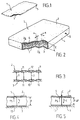
- Figure 1 is a perspective diagram, with torn parts of an air mattress according to the invention, in the state deflated.
- Figure 2 shows, also in perspective, the mattress according the invention in the inflated state, with parts torn off.
- FIG. 3 is a longitudinal section of a mattress produced at using a double-walled textile.
- Figure 4 is a sectional diagram of an area of the mattress swollen, at rest.
- Figure 5 finally shows, similarly to Figure 4, the area of the inflated mattress, under load.
- a air mattress 1 with two main walls respectively upper and lower 2, 3 connected according to their periphery by a side wall 4.
- These walls 2, 3 and 4 are in flexible flexible material, so that when the mattress 1 is deflated, as shown in Figure 1, walls 2 and 3 can come pressing one against the other, the side wall 4 being folded back, the assembly thus flattened which can itself be folded or rolled up to facilitate storage.
- At least one inflation valve 5 is provided for the introduction of a pressurized gas, in particular air, into the sealed chamber 6 closed delimited by walls 2, 3 and 4.
- the facing internal faces 2 a , 3 a of the main walls 2, 3 are connected by a plurality of elastic connecting wires 7 with significant elongation under tension.
- the elastic threads 7 have an elongation before breaking at least equal to 100% and preferably greater than 300%.
- the inflation pressure of the mattress 1 is chosen so as to separate the walls 2, 3 by a distance l sufficient to make the elastic threads 7 work in traction. In other words, the distance l is greater than the length, in the untensioned state, of the wires 7.
- the wires 7 are preferably substantially orthogonal to the walls main 2, 3.
- the surface density of the wires 7, on the faces 2 a , 3 a is at least equal to 1 wire per square centimeter of wall 2 or 3. This density is preferably less than or equal to 20 wires per square centimeter of wall.
- the average distance e between the connecting wires 7 is around 5 mm.
- the air mattress does not need to have a structure in juxtaposed elements such as joined flanges, used for mattresses classics.
- the mattress of the invention therefore ensures good continuity of the stress distribution on the surface of the wall support 2 or 3.
- a double-walled textile 2, 3 (see Figure 3) consisting of two layers textiles 9, 10 linked together by a plurality of elastic threads 7.
- the two textile layers 9, 10 are made airtight by coating and / or bonding and / or any other sealing means.
- the double-walled textiles are known and described, for example, in a article "USE OF THREE-DIMENSIONAL MATERIALS" by J.C. Malézieux published in the journal TUT (Textiles for technical use, 4th quarter 1991, n ° 2, pages 25 to 27).
- connecting threads between the two layers are standard textile threads or high tenacity with low elongations before rupture, included generally between 8 and 20% and leading to elongations in very low service given the inflation pressures generally used and which is not taken into account in practice.
- the connecting threads between the two plies are not elastic threads within the meaning of the invention.
- the connecting wires 7 between the plies 9, 10 consist of elastic threads with large elongation before rupture, for example greater than 300% and capable of reach 400% or 500%.
- Such elastic threads 7 are known in the industry. clothing to make elastic clothing.
- the layers 9 and 10 are produced with threads 11 of chain and 12 of conventional, standard or high tenacity weft. These sons of chain and weft are chosen according to the weaving criteria and the suitability for sealing. Take for example standard polyester flat yarn 1,100 decitex with ten threads of chain per centimeter and 10 threads of weft per centimeter.
- the connecting wires 7 are on the other hand elastic wires, for example of 600 dtex with an average modulus, between 0 and 200% elongation, of 0.2.10 -2 N / tex (0.2 gf / tex).
- a module of 10 -2 N / tex (or 1gf / tex) means that a 1 tex wire subjected to a force of 10 -2 N will undergo an elongation of 100%.
- the density of the connecting wires is 10 per square centimeter.
- the distance between layers 9 and 10, with the threads 7 stretched is chosen for example equal to 300 mm.
- the thickness of the mattress When the mattress is inflated to a pressure of 100 ⁇ 10 2 Pa (100 gf / cm 2 ) the thickness of the mattress, that is to say the distance between the plies 9 and 10, is approximately 180 mm. A pressure exerted on the mattress will produce, regardless of the membrane effect, a depression of 8 mm for each pressure increment of 10.10 2 Pa (10 gf / cm 2 ), up to the pressure of 100.10 2 Pa (100 gf / cm 2 ).
- This value of 5 mm can be increased by choosing a greater length of connecting wires for the same pressure of inflation.
- the inflatable mattress structure according to the invention after sealing of walls 2, 3 and 4 has a highly variable thickness depending on the inflation pressure, due to the capacity elongation of the connecting wires 7.
- FIG. 4 illustrates a fraction of the mattress 1 inflated under a pressure P, the lower wall 3 of which rests on a rigid support surface 13.
- zone S If a localized load C is applied in zone S, as shown schematically in Figure 5, the wall 2 tends to sink a distance ⁇ l such that the resulting tension of the elastic threads 7 concerned becomes T - C.
- f is the relation existing between the length of the elastic threads 7 and their tension.
- the variation of the tension of an elastic thread 7 may be proportional to its elongation, in the manner of a spring.
- the elastic threads 7 will therefore exert a force for retaining the wall 2 all the more reduced as they shorten under the effect of displacement of the wall.
- the force C necessary to move the wall 2 is therefore gradually increasing as the decrease the thickness of the mattress, that is to say the length l - ⁇ l of the wires 7.
- the air mattress 1 of the invention has a elastic behavior similar to that of a spring mattress, and so fundamentally different from that of an air mattress classic which is not able to oppose an increasing reaction in function of the deformation.
- the membrane effect described for the air mattress classic in case of localized action also exists for the mattress according to the invention.
- the calculation shows that it can represent a share sensitive to the load, for example 10 to 40%, assuming a seated person.
- the distribution of the forces exerted on the wall by the connecting wires is of very great continuity owing to the very high density of the connecting wires.
- a number of connecting wires is used from 1 to 20 per square centimeter; for a value of four connecting wires per cm 2 (for example), the average distance of the connecting wires is 5 mm.
- the mattress thus formed is therefore equivalent to a mattress with elastic springs which would have a spring every 5 mm in both directions, ie four springs per square centimeter.
- Such a mattress allows exceptional quality in the continuity of the distribution of contact stresses, far superior to most of the solutions currently known.
- the invention finally has another advantage, which is to be able vary the behavioral characteristics of the mattress by making vary the inflation pressure.
- a change in pressure has several effects.
- Another possibility is to use connecting wires of lengths different, which makes it possible to obtain a decreasing module depending on deformation.
Landscapes
- Mattresses And Other Support Structures For Chairs And Beds (AREA)
Claims (10)
- Luftmatratze mit zwei Hauptseitenwänden (2,3), die zur Bildung einer dicht verschlossenen Kammer (6) entlang ihres Randes miteinander verbunden sind, und mit wenigstens einem Ventil zum Einfüllen eines unter Druck stehenden Gases, insbesondere Druckluft, in die Kammer, wobei die sich gegenüberliegenden Innenflächen (2a,3a) der Hauptseitenwände durch zahlreiche auf Zug arbeitende Verbindungsmittel (7) miteinander verbunden sind und wobei der Aufblasdruck der Matratze so gewählt ist, daß die Hauptseitenwände in einem ausreichenden Abstand (l) voneinander beabstandet sind, damit die Verbindungsmittel (7) unter Spannung arbeiten, dadurch gekennzeichnet, daß die Verbindungsmittel (7) elastisch sind und eine Bruchdehnung von wenigstens 100% aufweisen, wobei der Abstand (1) größer als die Länge der Mittel (7) im ungespannten Zustand ist.
- Matratze gemäß Anspruch 1, dadurch gekennzeichnet, daß die elastischen Verbindungsmittel (7) eine Bruchdehnung von mehr als 300% aufweisen.
- Matratze gemäß einem der Ansprüche 1 oder 2, dadurch gekennzeichnet, daß die elastischen Verbindungsmittel (7) bei aufgeblasener Matratze im wesentlichen senkrecht zu den Hauptseitenwänden (2,3) verlaufen.
- Matratze gemäß einem der Ansprüche 1 bis 3, dadurch gekennzeichnet, daß die elastischen Verbindungsmittel (7) im ungespannten Zustand dieselbe Länge besitzen.
- Matratze gemäß einem der Ansprüche 1 bis 4, dadurch gekennzeichnet, daß die elastischen Verbindungsmittel (7) im ungespannten Zustand unterschiedliche Längen besitzen.
- Matratze gemäß einem der Ansprüche 1 bis 5, dadurch gekennzeichnet, daß die Flächendichte der elastischen Verbindungsmittel (7) wenigstens einem Verbindungsmittel pro cm2 Seitenwand und höchstens 20 Verbindungsmitteln pro cm2 Seitenwand entspricht.
- Matratze gemäß Anspruch 6, dadurch gekennzeichnet, daß der mittlere Abstand zwischen den Verbindungsmitteln etwa 5 mm beträgt.
- Matratze gemäß einem der Ansprüche 1 bis 7, dadurch gekennzeichnet, daß die Verbindungsmittel elastische Fäden sind.
- Matratze gemäß Anspruch 8, dadurch gekennzeichnet, daß sie aus einem doppelwandigen Textil hergestellt ist, das aus zwei Textilbahnen (9,10) besteht, die durch zahlreiche elastische Fäden (7) miteinander verbunden sind, wobei die beiden Textilbahnen (9,10) durch Beschichtung und/oder verklebung oder durch ein anderes Abdichtmittel luftdicht gemacht worden sind, wobei die Kett- und Schußfäden (11,12) jeder Bahn herkömmliche Textilfäden oder Fäden hoher Reißfestigkeit sind, die eine relativ geringe Bruchdehnung haben, während die elastischen Verbindungsfäden (7) zwischen den beiden Bahnen eine Bruchdehnung von über 100% aufweisen.
- Verfahren zur Herstellung einer Matratze gemäß einem der Ansprüche 8 oder 9, dadurch gekennzeichnet, daß man die elastischen Fäden (7) durch die Technik des Webens mit Spannfaden zwischen den beiden Textilbahnen (9,10) anordnet.
Applications Claiming Priority (2)
| Application Number | Priority Date | Filing Date | Title |
|---|---|---|---|
| FR9402318 | 1994-03-01 | ||
| FR9402318A FR2716788B1 (fr) | 1994-03-01 | 1994-03-01 | Matelas pneumatique. |
Publications (2)
| Publication Number | Publication Date |
|---|---|
| EP0678263A1 EP0678263A1 (de) | 1995-10-25 |
| EP0678263B1 true EP0678263B1 (de) | 1998-04-22 |
Family
ID=9460532
Family Applications (1)
| Application Number | Title | Priority Date | Filing Date |
|---|---|---|---|
| EP95400101A Expired - Lifetime EP0678263B1 (de) | 1994-03-01 | 1995-01-19 | Luftmatratze |
Country Status (6)
| Country | Link |
|---|---|
| EP (1) | EP0678263B1 (de) |
| JP (1) | JPH07255570A (de) |
| AT (1) | ATE165222T1 (de) |
| DE (1) | DE69502128T2 (de) |
| ES (1) | ES2117361T3 (de) |
| FR (1) | FR2716788B1 (de) |
Cited By (2)
| Publication number | Priority date | Publication date | Assignee | Title |
|---|---|---|---|---|
| CN100448383C (zh) * | 2005-07-04 | 2009-01-07 | 颉上股份有限公司 | 可充气气垫 |
| US9468583B2 (en) | 2013-07-18 | 2016-10-18 | Intex Marketing Ltd. | Inflatable spa |
Families Citing this family (13)
| Publication number | Priority date | Publication date | Assignee | Title |
|---|---|---|---|---|
| GB2328865B (en) * | 1997-08-27 | 2001-03-28 | Abf Ltd | A mattress |
| FR2778451A1 (fr) * | 1998-05-11 | 1999-11-12 | Claude Roy | Dispositif pour replier automatiquement une enveloppe gonflee par un fluide au cours de son vidage par depression |
| KR20000059492A (ko) * | 1999-03-04 | 2000-10-05 | 채정수 | 침구용 매트리스, 그의 제조방법 및 제조장치 |
| US6944428B2 (en) | 2001-08-06 | 2005-09-13 | Kabushiki Kaisha Toshiba | Image information input/output device and control system for the same using mobile device |
| WO2006006216A1 (ja) * | 2004-07-09 | 2006-01-19 | Ngc Corporation | 体操用緩衝マット |
| KR100825479B1 (ko) * | 2007-03-08 | 2008-04-28 | 목문수 | 에어 매트, 에어 매트의 내부 구조물 및 그 내부 구조물의제조방법 |
| JP4967168B2 (ja) * | 2008-06-17 | 2012-07-04 | ブルボン電子株式会社 | 介護補助具 |
| EP4477399A3 (de) | 2012-03-02 | 2025-03-12 | Intex Marketing Ltd. | Innere spannstruktur zur verwendung mit aufblasbaren vorrichtungen |
| GB2510849B (en) * | 2013-02-14 | 2015-04-29 | Lunar Caravans Ltd | Camper vehicle with inflatable mattress |
| CN103600502A (zh) | 2013-11-25 | 2014-02-26 | 明达实业(厦门)有限公司 | 一种充气产品熔着工艺 |
| CN109173107B (zh) * | 2018-11-16 | 2023-12-05 | 铜仁学院 | 一种免电气垫及组合式气垫 |
| FR3114228A1 (fr) | 2020-09-24 | 2022-03-25 | Airmaan | Elément de mobilier gonflable en une seule pièce de structure à point lancé |
| DE102025111472A1 (de) * | 2025-03-25 | 2026-02-19 | Siemens Healthineers Ag | Patientenauflage, Anordnung und Verfahren |
Family Cites Families (5)
| Publication number | Priority date | Publication date | Assignee | Title |
|---|---|---|---|---|
| GB598960A (en) * | 1945-02-28 | 1948-03-02 | Stirrat Andrew William Johnson | Improvements in or relating to pneumatic cushions, mattresses and other slab-like pneumatic structures |
| US2753573A (en) * | 1951-11-08 | 1956-07-10 | Edward D Barker | Inflatable mattress |
| US2872690A (en) * | 1955-08-15 | 1959-02-10 | Neisler Brothers Inc | Inflatable device of predetermined surface contour and method of making same |
| US3008213A (en) * | 1957-01-22 | 1961-11-14 | Us Rubber Co | Method of making an inflatable fabric |
| JPH04153313A (ja) * | 1990-10-15 | 1992-05-26 | Asahi Chem Ind Co Ltd | 極細ポリウレタン弾性糸 |
-
1994
- 1994-03-01 FR FR9402318A patent/FR2716788B1/fr not_active Expired - Fee Related
-
1995
- 1995-01-19 EP EP95400101A patent/EP0678263B1/de not_active Expired - Lifetime
- 1995-01-19 DE DE69502128T patent/DE69502128T2/de not_active Expired - Fee Related
- 1995-01-19 ES ES95400101T patent/ES2117361T3/es not_active Expired - Lifetime
- 1995-01-19 AT AT95400101T patent/ATE165222T1/de not_active IP Right Cessation
- 1995-01-31 JP JP7014650A patent/JPH07255570A/ja not_active Withdrawn
Non-Patent Citations (5)
| Title |
|---|
| CARACTERISTIQUES DES FIBRES CHIMIQUES A USAGES TECHNIQUES, édition de l'Industrie Textile, Paris * |
| MAUERSBERGER "AMERICAN HANDBOOK OF SYNTHETIC TEXTILES" (pages 244, 245) * |
| MORTON ET HEARLE "PHYSICAL PROPERTIES OF TEXTILE FIBRES" (pages 273,274,283,327) * |
| SAECHTLING "INTERNATIONAL PLASTICS HANDBOOK" (Table 4.37) * |
| TEXTILE DICTIONARY - VDI-Verlag GmbH (page 606) * |
Cited By (3)
| Publication number | Priority date | Publication date | Assignee | Title |
|---|---|---|---|---|
| CN100448383C (zh) * | 2005-07-04 | 2009-01-07 | 颉上股份有限公司 | 可充气气垫 |
| US9468583B2 (en) | 2013-07-18 | 2016-10-18 | Intex Marketing Ltd. | Inflatable spa |
| US9468582B2 (en) | 2013-07-18 | 2016-10-18 | Intex Marketing Ltd. | Inflatable spa |
Also Published As
| Publication number | Publication date |
|---|---|
| DE69502128T2 (de) | 1999-01-07 |
| ES2117361T3 (es) | 1998-08-01 |
| DE69502128D1 (de) | 1998-05-28 |
| FR2716788B1 (fr) | 1996-04-26 |
| FR2716788A1 (fr) | 1995-09-08 |
| JPH07255570A (ja) | 1995-10-09 |
| EP0678263A1 (de) | 1995-10-25 |
| ATE165222T1 (de) | 1998-05-15 |
Similar Documents
| Publication | Publication Date | Title |
|---|---|---|
| EP0678263B1 (de) | Luftmatratze | |
| BE1004765A3 (fr) | Toile pour machine a papier a deux couches. | |
| EP0184262B1 (de) | Steuerbarer aerostatischer Ballon | |
| FR2833239A1 (fr) | Ballon resistant a la pression | |
| OA12796A (en) | Dispositif pour limiter le flambage latéral des nappes d'armures d'une conduite flexible. | |
| FR2488956A1 (fr) | Organe de transmission de force souple en torsion pour mecanismes | |
| FR2711978A1 (fr) | Appareil d'application de tension du type circulaire pour des tôles refendues. | |
| BE1024072B1 (fr) | Dirigeable hydride a enveloppe exterieure souple et compartimentee | |
| FR2544434A1 (fr) | Courroie de transmission | |
| WO1995031260A1 (fr) | Ski de fond | |
| EP0912354B1 (de) | Aufblasbare struktur für luftreifen | |
| FR2467091A1 (fr) | Pneumatique de vehicule comportant une ceinture | |
| FR2799622A1 (fr) | Matelas a ressorts ensaches | |
| FR2754488A1 (fr) | Couche de renfort de la ceinture d'un pneumatique de vehicule | |
| FR2670156A1 (fr) | Dispositif de retroussage pour tambour de fabrication de pneumatique. | |
| FR2673366A1 (fr) | Housse pour siege, en particulier pour siege de voiture. | |
| EP0196990B1 (de) | Vorrichtung zur Reduktion von räumlicher Abmessung in einer Vorzugsrichtung durch Unterdruck | |
| EP3931413A1 (de) | Verankerungsvorrichtung zur verankerung eines pfahls eines strandsonnenschirms im sand oder sandigen boden | |
| FR2747343A1 (fr) | Dispositif correcteur d'assiette pour vehicules a suspension par coussins elastiques gonflables | |
| EP0601624A1 (de) | Aerodynamisches Lager mit Flüssigkeitsfilm | |
| FR3163966A1 (fr) | Ensemble gonflable pour piscine | |
| FR2698855A1 (fr) | Dispositif pour l'emballage et la conservation d'une quantité variable de disques abrasifs. | |
| WO2009092909A1 (fr) | Dispositif de support et de transport de charges sur coussin d'air | |
| EP0504195B1 (de) | Verbesserte massagevorrichtung für einen teil des menschlichen körpers mit gerichteter und periodischer wirkung | |
| FR2939641A1 (fr) | Matelas autogonflant therapeutique |
Legal Events
| Date | Code | Title | Description |
|---|---|---|---|
| PUAI | Public reference made under article 153(3) epc to a published international application that has entered the european phase |
Free format text: ORIGINAL CODE: 0009012 |
|
| 17P | Request for examination filed |
Effective date: 19950619 |
|
| AK | Designated contracting states |
Kind code of ref document: A1 Designated state(s): AT BE CH DE DK ES FR GB GR IE IT LI LU MC NL PT SE |
|
| 17Q | First examination report despatched |
Effective date: 19960401 |
|
| GRAG | Despatch of communication of intention to grant |
Free format text: ORIGINAL CODE: EPIDOS AGRA |
|
| GRAG | Despatch of communication of intention to grant |
Free format text: ORIGINAL CODE: EPIDOS AGRA |
|
| GRAH | Despatch of communication of intention to grant a patent |
Free format text: ORIGINAL CODE: EPIDOS IGRA |
|
| GRAH | Despatch of communication of intention to grant a patent |
Free format text: ORIGINAL CODE: EPIDOS IGRA |
|
| GRAA | (expected) grant |
Free format text: ORIGINAL CODE: 0009210 |
|
| AK | Designated contracting states |
Kind code of ref document: B1 Designated state(s): AT BE CH DE DK ES FR GB GR IE IT LI LU MC NL PT SE |
|
| PG25 | Lapsed in a contracting state [announced via postgrant information from national office to epo] |
Ref country code: NL Free format text: LAPSE BECAUSE OF FAILURE TO SUBMIT A TRANSLATION OF THE DESCRIPTION OR TO PAY THE FEE WITHIN THE PRESCRIBED TIME-LIMIT Effective date: 19980422 Ref country code: GR Free format text: LAPSE BECAUSE OF NON-PAYMENT OF DUE FEES Effective date: 19980422 Ref country code: AT Free format text: LAPSE BECAUSE OF FAILURE TO SUBMIT A TRANSLATION OF THE DESCRIPTION OR TO PAY THE FEE WITHIN THE PRESCRIBED TIME-LIMIT Effective date: 19980422 |
|
| REF | Corresponds to: |
Ref document number: 165222 Country of ref document: AT Date of ref document: 19980515 Kind code of ref document: T |
|
| REG | Reference to a national code |
Ref country code: CH Ref legal event code: EP |
|
| REF | Corresponds to: |
Ref document number: 69502128 Country of ref document: DE Date of ref document: 19980528 |
|
| REG | Reference to a national code |
Ref country code: CH Ref legal event code: NV Representative=s name: KIRKER & CIE SA |
|
| ITF | It: translation for a ep patent filed | ||
| GBT | Gb: translation of ep patent filed (gb section 77(6)(a)/1977) |
Effective date: 19980615 |
|
| PG25 | Lapsed in a contracting state [announced via postgrant information from national office to epo] |
Ref country code: SE Free format text: LAPSE BECAUSE OF FAILURE TO SUBMIT A TRANSLATION OF THE DESCRIPTION OR TO PAY THE FEE WITHIN THE PRESCRIBED TIME-LIMIT Effective date: 19980722 Ref country code: PT Free format text: LAPSE BECAUSE OF FAILURE TO SUBMIT A TRANSLATION OF THE DESCRIPTION OR TO PAY THE FEE WITHIN THE PRESCRIBED TIME-LIMIT Effective date: 19980722 Ref country code: DK Free format text: LAPSE BECAUSE OF FAILURE TO SUBMIT A TRANSLATION OF THE DESCRIPTION OR TO PAY THE FEE WITHIN THE PRESCRIBED TIME-LIMIT Effective date: 19980722 |
|
| REG | Reference to a national code |
Ref country code: IE Ref legal event code: FG4D Free format text: 79969 |
|
| REG | Reference to a national code |
Ref country code: ES Ref legal event code: FG2A Ref document number: 2117361 Country of ref document: ES Kind code of ref document: T3 |
|
| NLV1 | Nl: lapsed or annulled due to failure to fulfill the requirements of art. 29p and 29m of the patents act | ||
| PG25 | Lapsed in a contracting state [announced via postgrant information from national office to epo] |
Ref country code: IE Free format text: LAPSE BECAUSE OF NON-PAYMENT OF DUE FEES Effective date: 19981023 |
|
| REG | Reference to a national code |
Ref country code: IE Ref legal event code: FD4D Ref document number: 79969 Country of ref document: IE |
|
| PGFP | Annual fee paid to national office [announced via postgrant information from national office to epo] |
Ref country code: GB Payment date: 19990112 Year of fee payment: 5 |
|
| PGFP | Annual fee paid to national office [announced via postgrant information from national office to epo] |
Ref country code: ES Payment date: 19990118 Year of fee payment: 5 |
|
| PG25 | Lapsed in a contracting state [announced via postgrant information from national office to epo] |
Ref country code: LU Free format text: LAPSE BECAUSE OF NON-PAYMENT OF DUE FEES Effective date: 19990119 |
|
| PGFP | Annual fee paid to national office [announced via postgrant information from national office to epo] |
Ref country code: CH Payment date: 19990120 Year of fee payment: 5 |
|
| PGFP | Annual fee paid to national office [announced via postgrant information from national office to epo] |
Ref country code: BE Payment date: 19990212 Year of fee payment: 5 |
|
| PLBE | No opposition filed within time limit |
Free format text: ORIGINAL CODE: 0009261 |
|
| STAA | Information on the status of an ep patent application or granted ep patent |
Free format text: STATUS: NO OPPOSITION FILED WITHIN TIME LIMIT |
|
| PGFP | Annual fee paid to national office [announced via postgrant information from national office to epo] |
Ref country code: DE Payment date: 19990330 Year of fee payment: 5 |
|
| 26N | No opposition filed | ||
| PG25 | Lapsed in a contracting state [announced via postgrant information from national office to epo] |
Ref country code: MC Free format text: LAPSE BECAUSE OF NON-PAYMENT OF DUE FEES Effective date: 19990731 |
|
| PG25 | Lapsed in a contracting state [announced via postgrant information from national office to epo] |
Ref country code: GB Free format text: LAPSE BECAUSE OF NON-PAYMENT OF DUE FEES Effective date: 20000119 |
|
| PG25 | Lapsed in a contracting state [announced via postgrant information from national office to epo] |
Ref country code: ES Free format text: LAPSE BECAUSE OF NON-PAYMENT OF DUE FEES Effective date: 20000120 |
|
| PG25 | Lapsed in a contracting state [announced via postgrant information from national office to epo] |
Ref country code: LI Free format text: LAPSE BECAUSE OF NON-PAYMENT OF DUE FEES Effective date: 20000131 Ref country code: CH Free format text: LAPSE BECAUSE OF NON-PAYMENT OF DUE FEES Effective date: 20000131 Ref country code: BE Free format text: LAPSE BECAUSE OF NON-PAYMENT OF DUE FEES Effective date: 20000131 |
|
| BERE | Be: lapsed |
Owner name: LEFLAIVE ETIENNE Effective date: 20000131 |
|
| GBPC | Gb: european patent ceased through non-payment of renewal fee |
Effective date: 20000119 |
|
| REG | Reference to a national code |
Ref country code: CH Ref legal event code: PL |
|
| PG25 | Lapsed in a contracting state [announced via postgrant information from national office to epo] |
Ref country code: DE Free format text: LAPSE BECAUSE OF NON-PAYMENT OF DUE FEES Effective date: 20001101 |
|
| REG | Reference to a national code |
Ref country code: ES Ref legal event code: FD2A Effective date: 20010910 |
|
| PGFP | Annual fee paid to national office [announced via postgrant information from national office to epo] |
Ref country code: FR Payment date: 20020130 Year of fee payment: 8 |
|
| PG25 | Lapsed in a contracting state [announced via postgrant information from national office to epo] |
Ref country code: FR Free format text: LAPSE BECAUSE OF NON-PAYMENT OF DUE FEES Effective date: 20030930 |
|
| REG | Reference to a national code |
Ref country code: FR Ref legal event code: ST |
|
| PG25 | Lapsed in a contracting state [announced via postgrant information from national office to epo] |
Ref country code: IT Free format text: LAPSE BECAUSE OF NON-PAYMENT OF DUE FEES;WARNING: LAPSES OF ITALIAN PATENTS WITH EFFECTIVE DATE BEFORE 2007 MAY HAVE OCCURRED AT ANY TIME BEFORE 2007. THE CORRECT EFFECTIVE DATE MAY BE DIFFERENT FROM THE ONE RECORDED. Effective date: 20050119 |