EP0678367B1 - Vorrichtung zum Formen von Polyurethanschaum - Google Patents
Vorrichtung zum Formen von Polyurethanschaum Download PDFInfo
- Publication number
- EP0678367B1 EP0678367B1 EP95110012A EP95110012A EP0678367B1 EP 0678367 B1 EP0678367 B1 EP 0678367B1 EP 95110012 A EP95110012 A EP 95110012A EP 95110012 A EP95110012 A EP 95110012A EP 0678367 B1 EP0678367 B1 EP 0678367B1
- Authority
- EP
- European Patent Office
- Prior art keywords
- cavity
- mold
- polyurethane material
- vacuum box
- vent hole
- Prior art date
- Legal status (The legal status is an assumption and is not a legal conclusion. Google has not performed a legal analysis and makes no representation as to the accuracy of the status listed.)
- Expired - Lifetime
Links
- 238000000465 moulding Methods 0.000 title claims description 37
- 229920005830 Polyurethane Foam Polymers 0.000 title claims description 24
- 239000011496 polyurethane foam Substances 0.000 title claims description 24
- 239000000463 material Substances 0.000 claims description 71
- 229920002635 polyurethane Polymers 0.000 claims description 64
- 239000004814 polyurethane Substances 0.000 claims description 64
- 230000007246 mechanism Effects 0.000 claims description 17
- 230000013011 mating Effects 0.000 claims description 12
- 238000004891 communication Methods 0.000 claims description 3
- YMWUJEATGCHHMB-UHFFFAOYSA-N Dichloromethane Chemical compound ClCCl YMWUJEATGCHHMB-UHFFFAOYSA-N 0.000 description 27
- CURLTUGMZLYLDI-UHFFFAOYSA-N Carbon dioxide Chemical compound O=C=O CURLTUGMZLYLDI-UHFFFAOYSA-N 0.000 description 18
- 238000002347 injection Methods 0.000 description 17
- 239000007924 injection Substances 0.000 description 17
- 238000009835 boiling Methods 0.000 description 15
- XLYOFNOQVPJJNP-UHFFFAOYSA-N water Substances O XLYOFNOQVPJJNP-UHFFFAOYSA-N 0.000 description 15
- 239000004604 Blowing Agent Substances 0.000 description 13
- 238000005187 foaming Methods 0.000 description 13
- 239000002904 solvent Substances 0.000 description 13
- 239000012948 isocyanate Substances 0.000 description 12
- 150000002513 isocyanates Chemical class 0.000 description 12
- 229920005862 polyol Polymers 0.000 description 11
- 150000003077 polyols Chemical class 0.000 description 11
- 238000000034 method Methods 0.000 description 10
- 238000013022 venting Methods 0.000 description 10
- 229910002092 carbon dioxide Inorganic materials 0.000 description 9
- 239000001569 carbon dioxide Substances 0.000 description 9
- 239000010410 layer Substances 0.000 description 9
- 238000006243 chemical reaction Methods 0.000 description 7
- 239000006260 foam Substances 0.000 description 6
- 238000007872 degassing Methods 0.000 description 3
- 230000000694 effects Effects 0.000 description 3
- 230000009467 reduction Effects 0.000 description 3
- 238000007789 sealing Methods 0.000 description 3
- 239000000126 substance Substances 0.000 description 3
- 206010016322 Feeling abnormal Diseases 0.000 description 2
- 230000009471 action Effects 0.000 description 2
- 239000004202 carbamide Substances 0.000 description 2
- 238000004519 manufacturing process Methods 0.000 description 2
- 239000000203 mixture Substances 0.000 description 2
- NJPPVKZQTLUDBO-UHFFFAOYSA-N novaluron Chemical compound C1=C(Cl)C(OC(F)(F)C(OC(F)(F)F)F)=CC=C1NC(=O)NC(=O)C1=C(F)C=CC=C1F NJPPVKZQTLUDBO-UHFFFAOYSA-N 0.000 description 2
- CBENFWSGALASAD-UHFFFAOYSA-N Ozone Chemical compound [O-][O+]=O CBENFWSGALASAD-UHFFFAOYSA-N 0.000 description 1
- 230000002730 additional effect Effects 0.000 description 1
- 238000005273 aeration Methods 0.000 description 1
- XAGFODPZIPBFFR-UHFFFAOYSA-N aluminium Chemical compound [Al] XAGFODPZIPBFFR-UHFFFAOYSA-N 0.000 description 1
- 229910052782 aluminium Inorganic materials 0.000 description 1
- 238000007664 blowing Methods 0.000 description 1
- 230000000711 cancerogenic effect Effects 0.000 description 1
- 231100000315 carcinogenic Toxicity 0.000 description 1
- 239000000919 ceramic Substances 0.000 description 1
- 230000008859 change Effects 0.000 description 1
- 230000007423 decrease Effects 0.000 description 1
- 238000005516 engineering process Methods 0.000 description 1
- 238000009472 formulation Methods 0.000 description 1
- 238000001746 injection moulding Methods 0.000 description 1
- 239000007788 liquid Substances 0.000 description 1
- 238000003754 machining Methods 0.000 description 1
- 229920003023 plastic Polymers 0.000 description 1
- 239000004033 plastic Substances 0.000 description 1
- 239000005437 stratosphere Substances 0.000 description 1
- 239000002344 surface layer Substances 0.000 description 1
- 229920005992 thermoplastic resin Polymers 0.000 description 1
- 231100000331 toxic Toxicity 0.000 description 1
- 230000002588 toxic effect Effects 0.000 description 1
- 238000009834 vaporization Methods 0.000 description 1
- 230000008016 vaporization Effects 0.000 description 1
Images


Classifications
-
- B—PERFORMING OPERATIONS; TRANSPORTING
- B29—WORKING OF PLASTICS; WORKING OF SUBSTANCES IN A PLASTIC STATE IN GENERAL
- B29C—SHAPING OR JOINING OF PLASTICS; SHAPING OF MATERIAL IN A PLASTIC STATE, NOT OTHERWISE PROVIDED FOR; AFTER-TREATMENT OF THE SHAPED PRODUCTS, e.g. REPAIRING
- B29C44/00—Shaping by internal pressure generated in the material, e.g. swelling or foaming ; Producing porous or cellular expanded plastics articles
- B29C44/34—Auxiliary operations
- B29C44/58—Moulds
- B29C44/588—Moulds with means for venting, e.g. releasing foaming gas
-
- B—PERFORMING OPERATIONS; TRANSPORTING
- B29—WORKING OF PLASTICS; WORKING OF SUBSTANCES IN A PLASTIC STATE IN GENERAL
- B29C—SHAPING OR JOINING OF PLASTICS; SHAPING OF MATERIAL IN A PLASTIC STATE, NOT OTHERWISE PROVIDED FOR; AFTER-TREATMENT OF THE SHAPED PRODUCTS, e.g. REPAIRING
- B29C44/00—Shaping by internal pressure generated in the material, e.g. swelling or foaming ; Producing porous or cellular expanded plastics articles
- B29C44/34—Auxiliary operations
- B29C44/3402—Details of processes or apparatus for reducing environmental damage or for working-up compositions comprising inert blowing agents or biodegradable components
-
- B—PERFORMING OPERATIONS; TRANSPORTING
- B29—WORKING OF PLASTICS; WORKING OF SUBSTANCES IN A PLASTIC STATE IN GENERAL
- B29C—SHAPING OR JOINING OF PLASTICS; SHAPING OF MATERIAL IN A PLASTIC STATE, NOT OTHERWISE PROVIDED FOR; AFTER-TREATMENT OF THE SHAPED PRODUCTS, e.g. REPAIRING
- B29C44/00—Shaping by internal pressure generated in the material, e.g. swelling or foaming ; Producing porous or cellular expanded plastics articles
- B29C44/34—Auxiliary operations
- B29C44/58—Moulds
-
- B—PERFORMING OPERATIONS; TRANSPORTING
- B29—WORKING OF PLASTICS; WORKING OF SUBSTANCES IN A PLASTIC STATE IN GENERAL
- B29C—SHAPING OR JOINING OF PLASTICS; SHAPING OF MATERIAL IN A PLASTIC STATE, NOT OTHERWISE PROVIDED FOR; AFTER-TREATMENT OF THE SHAPED PRODUCTS, e.g. REPAIRING
- B29C44/00—Shaping by internal pressure generated in the material, e.g. swelling or foaming ; Producing porous or cellular expanded plastics articles
- B29C44/34—Auxiliary operations
- B29C44/60—Measuring, controlling or regulating
-
- B—PERFORMING OPERATIONS; TRANSPORTING
- B29—WORKING OF PLASTICS; WORKING OF SUBSTANCES IN A PLASTIC STATE IN GENERAL
- B29K—INDEXING SCHEME ASSOCIATED WITH SUBCLASSES B29B, B29C OR B29D, RELATING TO MOULDING MATERIALS OR TO MATERIALS FOR MOULDS, REINFORCEMENTS, FILLERS OR PREFORMED PARTS, e.g. INSERTS
- B29K2075/00—Use of PU, i.e. polyureas or polyurethanes or derivatives thereof, as moulding material
-
- Y—GENERAL TAGGING OF NEW TECHNOLOGICAL DEVELOPMENTS; GENERAL TAGGING OF CROSS-SECTIONAL TECHNOLOGIES SPANNING OVER SEVERAL SECTIONS OF THE IPC; TECHNICAL SUBJECTS COVERED BY FORMER USPC CROSS-REFERENCE ART COLLECTIONS [XRACs] AND DIGESTS
- Y10—TECHNICAL SUBJECTS COVERED BY FORMER USPC
- Y10S—TECHNICAL SUBJECTS COVERED BY FORMER USPC CROSS-REFERENCE ART COLLECTIONS [XRACs] AND DIGESTS
- Y10S264/00—Plastic and nonmetallic article shaping or treating: processes
- Y10S264/78—Processes of molding using vacuum
-
- Y—GENERAL TAGGING OF NEW TECHNOLOGICAL DEVELOPMENTS; GENERAL TAGGING OF CROSS-SECTIONAL TECHNOLOGIES SPANNING OVER SEVERAL SECTIONS OF THE IPC; TECHNICAL SUBJECTS COVERED BY FORMER USPC CROSS-REFERENCE ART COLLECTIONS [XRACs] AND DIGESTS
- Y10—TECHNICAL SUBJECTS COVERED BY FORMER USPC
- Y10S—TECHNICAL SUBJECTS COVERED BY FORMER USPC CROSS-REFERENCE ART COLLECTIONS [XRACs] AND DIGESTS
- Y10S425/00—Plastic article or earthenware shaping or treating: apparatus
- Y10S425/06—Vacuum
-
- Y—GENERAL TAGGING OF NEW TECHNOLOGICAL DEVELOPMENTS; GENERAL TAGGING OF CROSS-SECTIONAL TECHNOLOGIES SPANNING OVER SEVERAL SECTIONS OF THE IPC; TECHNICAL SUBJECTS COVERED BY FORMER USPC CROSS-REFERENCE ART COLLECTIONS [XRACs] AND DIGESTS
- Y10—TECHNICAL SUBJECTS COVERED BY FORMER USPC
- Y10S—TECHNICAL SUBJECTS COVERED BY FORMER USPC CROSS-REFERENCE ART COLLECTIONS [XRACs] AND DIGESTS
- Y10S425/00—Plastic article or earthenware shaping or treating: apparatus
- Y10S425/812—Venting
Definitions
- the present invention relates to an apparatus for molding a polyurethane foam.
- the apparatus is suitable for reactive injection molding (RIM for short) of polyurethane foams such as automotive steering wheel, steering wheel pad, instrument panel, console boxe lid, glove box lid, headrest, armrest, and air spoiler.
- RIM reactive injection molding
- Polyurethane foams are usually produced by injecting a liquid polyurethane material composed of a polyol component, isocyanate component, and blowing agent, into the mold cavity, permitting the polyurethane material to expand, thereby permitting it to flow and fill the mold cavity, and demolding the polyurethane foam after curing.
- blowing agents are fluorochlorohydrocarbons (such as "Fleon", a trade name of DuPont), methylene chloride, and water. An adequate one is selected according to the use and kind of the polyurethane foam to be produced.
- Fleon and methylene chloride which are low-boiling solvents expand the polyurethane material when it is vaporized by heat generated by the reaction of the polyol and isocyanate components, whereas water expands the polyurethane material when it evolves carbon dioxide gas upon reaction with the isocyanate component.
- low-boiling solvents such as Fleon and methylene chloride
- blowing agent such as Fleon and methylene chloride
- polyurethane foams such as automotive steering wheel and steering wheel pad, which are composed of a surface skin layer of high density (without expansion or with a low expansion ratio) and an internal core of low density (with a high expansion ratio).
- low-boiling solvents such as Fleon and methylene chloride
- Fleon and methylene chloride have many advantages and find use as an essential blowing agent for the molding of polyurethane foams composed of a skin layer and a core part.
- Fleon and methylene chloride have recently met with the worldwide campaign against their use. It is said that Fleon, once released, diffuses into the atmosphere and destroys the ozone layer of the stratosphere, resulting in an increase of ultraviolet rays reaching the earth's surface. Methylene chloride is considered to be toxic and carcinogenic.
- GB-A-2 092 509 discloses an apparatus for molding a polyurethane foam comprising a mold made up of at least two split molds which are opened and closed and which define a cavity, a vacuum box surrounding said mold, a space formed between the mold and the vacuum box, a depressurizing means operatively connected to said space, a mechanism for injecting a polyurethane material into the cavity, and a plurality of vent holes for communication of the cavity with the space. Many vent holes are provided and distributed over the upper surface of the split mold.
- low-boiling solvents such as Fleon and methylene chloride
- Japanese Patent Laid-open Nos. 63237/1980 and 63238/1980 disclose a method of producing a polyurethane foam which comprises evacuating the mold through a small groove formed in the mold and connected to a vacuum pump.
- This method is intended to produce a uniform rigid polyurethane foam free of voids and blisters in the surface layer, but is not intended to eliminate the use of Fleon (as in the present invention).
- Fleon as in the present invention.
- they do not specify any substance as the blowing agent. It is only possible to speculate that low-boiling solvents such as Fleon are used as the blowing agent.
- the object of the present invention is achieved by the apparatus for molding a polyurethane foam as defined in claim 1.
- the depressurizing means are capable of lowering the atmospheric pressure in the cavity, and a venting mechanism opens and closes the final fill position of the cavity to the depressurizing means.
- the depressurizing unit comprises a vacuum box surrounding the mold, with a space interposed between them, and a vacuum pump connected to the vacuum box.
- the depressurizing unit may comprise a groove formed in the periphery of the mold cavity so as to form a space when the mold is closed, and a vacuum pump connected to the groove.
- the venting mechanism comprises a vent hole formed at the final fill position of the mold cavity.
- a hydraulic cylinder may be provided with a plug to open and close the vent hole.
- the apparatus further comprises a control means which closes the final fill position to the depressurizing unit for a prescribed period of time after the injection of the polyurethane material into the cavity, and opens the final fill position to the depressurizing unit after the prescribed period of time has passed.
- the polyurethane material undergoes a change which varies from position to position in the cavity.
- the polyurethane material sufficiently expands to form the core of low density because of the foaming action and expanding action by water which are explained below.
- the apparatus is provided with a depressurizing unit to lower the atmospheric pressure in the cavity during the molding of a polyurethane foam.
- the apparatus is constructed such that the vacuum box of the depressurizing unit surrounds the mold, with a space interposed between them.
- the vacuum box is evacuated by a vacuum pump so that air escapes from the cavity through the gap (air vent land) between the mating mold surfaces or through the venting mechanism.
- the vacuum box surrounding the mold prevents air from entering the evacuated mold cavity.
- the space between the vacuum box and the mold functions as a buffer for evacuation.
- the periphery of the mold cavity may have a groove which functions as the space when the mold is closed. It obviates the vacuum box in the apparatus and hence contributes to the reduction of the size of the molding apparatus. Moreover, it also leads to the reduction of the volume of the space, which reduces the time required for evacuation.
- the venting mechanism is of simple structure which operates surely.
- the control means controls the venting mechanism so as to close the final fill position to the depressurizing unit for a prescribed period of time after the injection of the polyurethane material into the cavity.
- This arrangement permits the atmospheric pressure in the cavity to be kept high spontaneously as the polyurethane material flows.
- the control means controls the venting mechanism so as to open the final fill position to the depressurizing unit after the lapse of the prescribed period of time. This arrangement discharges from the cavity the fore-end of the flow of the polyurethane material which goes beyond the final fill position. Therefore, this apparatus helps practice the molding method.
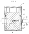
- the first example of the present invention which is embodied in the molding of a steering wheel pad will be described with reference to Figs. 1 to 3 showing the molding apparatus used in the example.
- the molding apparatus is constructed of a mold 1 (composed of 2 split molds), a vacuum box 11 which encloses the mold 1, forming a space K between the vacuum box and the mold, a mechanism 21 attached to the vacuum box 11 which injects the polyurethane material into the cavity 4 of the mold 1, and a vacuum pump (not shown) to evacuate the vacuum box 11.
- a vacuum box 11 which encloses the mold 1 forming a space K between the vacuum box and the mold
- a mechanism 21 attached to the vacuum box 11 which injects the polyurethane material into the cavity 4 of the mold 1
- a vacuum pump not shown
- the mold 1 has a vent hole 5 at the final fill position L of the polyurethane material in the cavity 4.
- the mold 1 is made up of 2 split molds, that is, a stationary mold 2 and a movable mold 3.
- the split molds form the cavity 4, when closed.
- the split molds also have grooves on their mating mold surfaces 2a and 3a which form, when closed, a sprue 6, runner 7, and gate 8 through which the polyurethane material flows.
- the mating mold surfaces 2a and 3a form air vent lands with a clearance of 0.03-0.06 mm (which is unavoidable due to the limited machining precision) along the entire periphery of the cavity 4.
- the air vent lands permit degassing (mentioned later).
- the vent hole 5 has a diameter of 1-10 mm. With a diameter smaller than 1 mm, the vent hole 5 does not permit complete degassing (because the final fill position of the polyurethane material fluctuates). With a diameter larger than 10 mm, the vent hole 5 leaves an unsightly mark after demolding.
- the mold 1 may be an inexpensive aluminum mold or electroformed mold because it does not need high pressure resistance. (The foaming pressure is usually 50-500 kPa.)
- the vacuum box 11 is large enough to enclose the mold 1, forming the space K between the mold 1 and the vacuum box 11.
- the vacuum box 11 is made up of an upper casing 12 to which is fixed the stationary mold 2, and a lower casing 13 to which is fixed the movable mold 3.
- a sealing member (O-ring) 14 To the periphery of the lower casing 13 is fitted a sealing member (O-ring) 14 to facilitate the tight closing of the vacuum box 11.
- the lower casing 13 is provided with a suction port 16 which is connected to a vacuum pump (not shown) through a suction hose 15.
- the upper casing 12 is provided with an air cylinder 19 to vertically actuate a plug 18 which opens and closes the vent hole 5. (This is not mandatory.)
- the injecting mechanism 21 is made up of a mixing head 22 and a injection nozzle 23.
- the injection nozzle 23 is connected to the sprue 6 of the mold 1 through an O-rings 24.
- the mixing head 22 is connected to a polyol tank and an isocyanate tank (both not shown) through high-pressure pumps and circulating pipes, so that the polyol component and isocyanate component are vigorously mixed at the time of injection and are recycled to their respective tanks when injection is not performed.
- the polyurethane material used in this example is composed of 100 parts by weight polyol component, 0.1-0.6 part by weight of water, and an isocyanate component in an amount corresponding to an index of 110.
- the above-mentioned apparatus (made up of the mold 1 and the vacuum box 11) is used in the following manner to carry out the foaming operation.
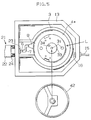
- the second example of the present invention which is embodied in the molding of a steering wheel will be described with reference to Figs. 4 to 8 showing the molding apparatus used in the example.
- the molding apparatus has many parts common to that in the first example. Basically, it is constructed of a mold 1, a vacuum box 11, a material injecting mechanism 21, and a vacuum pump (not shown). Those parts common to that in the first example are indicated by like reference numbers in Figs. 4 to 7, and their description is not repeated except for the supplementary description that follows.
- the mold 1 is designed to form the covering 43 on the ring of the steering wheel 41. It is made up of an upper stationary mold 2 and a lower movable mold 3. They have a groove 4a so that they form a circular cavity 4 when they are closed. At the center of the cross section of the cavity is placed the ring of the steering wheel core 42. To this groove 4a is connected a gate 8 (as shown at the left side in Fig. 4). The polyurethane material M is injected into the cavity 4 through the gate 8. In the cavity 4 the polyurethane material M splits into two flows which join at the final fill position L (at the right side in Fig. 6) after filling the cavity 4.
- venting mechanism which is made up of a vent hole 5 (which leads to the space K in the vacuum box 11) and an air cylinder 19 provided with a plug 18 to open and close the vent hole 5.
- the rod of the air cylinder 19 passes through a plate 20 which prevents the excess part 46 of the polyurethane material M (mentioned later) from blowing off upward.
- the venting mechanism is provided with a control means (not shown) which keeps the vent hole 5 closed for a prescribed period of time in which the polyurethane material M injected into the cavity 4 fills the cavity 4, and opens the vent hole 5 after the lapse of a prescribed period of time.
- the molds 2 and 3 Inside the groove 4a of the stationary mold 2 and movable mold 3 are fitting units 31 for the positioning of the molds 2 and 3 (when closed), and a hole 32 and a pedestal 33 which hold the boss of the steering wheel core 42.
- the pedestal 33 has an ejector pin 34 to demold the steering wheel 41 after molding.
- the molds 2 and 3 have the mating mold surfaces 2a and 3a which form a gap of 0.03-0.06 mm when they are closed.
- the stationary mold 2 and the upper casing 12 are integrally constructed, and the movable mold 3 and the lower casing 13 are integrally constructed.
- the lower casing 13 is attached to a hydraulic cylinder ram (not shown) so that it is moved up and down as the mold is closed and opened. At its raised position, the periphery of the lower casing 13 is in contact with the periphery of the upper casing 12.
- the injecting mechanism 21 is connected to an injection nozzle 23 (which passes through the lower casing 13 and reaches the movable mold 3) tightly by the aid of a sealing member 24 (O-rings), which prevents the leakage of air through the gap between the lower casing 13 and the injection nozzle 23 when the vacuum box 11 is evacuated.
- the polyurethane material used in this example is composed of 100 parts by weight polyol component, 0.1-0.6 part by weight of water, and an isocyanate component in an amount corresponding to an index of 110.
- the above-mentioned apparatus is used in the following manner to carry out the foaming operation.
- the molding of the steering wheel covering 43 presents the following problems (a) and (b) characteristic of the steering wheel, in addition to the above-mentioned problems associated with using Fleon.
- problems are solved if molding is carried out according to this example. It follows therefore that the method of this example is suitable for molding the steering wheel covering.
- the present invention produces the following effects.
- low-boiling solvents such as Fleon and methylene chloride which pose problems when used as a blowing agent is obviated. Nevertheless, it permits the production of a polyurethane foam having the same good appearance and soft feeling as the one produced with a low-boiling solvent.
- the obtained polyurethane foam has a higher extent of foaming than that in the case of the first molding method.
- a polyurethane foam is obtained in which the core part has a uniform extent of foaming and hence has a uniform quality.
- This polyurethane foam is free of pinholes, voids, and short shot.
- the obtained polyurethane foam has a high extent of foaming.
- This polyurethane foam is free of pinholes, voids, and short shot, as in the case of the third molding method.
- the molding apparatus permits the cavity pressure to be reduced easily and keeps the evacuated cavity isolated from the atmosphere.
- the apparatus provides a space between the mold and the vacuum box which functions as a buffer for evacuation.
- the molding apparatus can be made simple and small. It permits the reduction of time for evacuation.
- the molding apparatus provides a venting mechanism which is simple and yet works surely.
Landscapes
- Health & Medical Sciences (AREA)
- Life Sciences & Earth Sciences (AREA)
- Biodiversity & Conservation Biology (AREA)
- Environmental & Geological Engineering (AREA)
- Environmental Sciences (AREA)
- Toxicology (AREA)
- Casting Or Compression Moulding Of Plastics Or The Like (AREA)
- Moulds For Moulding Plastics Or The Like (AREA)
- Manufacture Of Porous Articles, And Recovery And Treatment Of Waste Products (AREA)
- Injection Moulding Of Plastics Or The Like (AREA)
- Molding Of Porous Articles (AREA)
Claims (7)
- Vorrichtung zum Formen eines Polyurethanschaumes miteiner Form (1) aus mindestens zwei Teilformen (2, 3), die geöffnet und geschlossen werden;einem in der Form (1) ausgebildeten Hohlraum (4);einer die Form umgebenden Vakuumbox (11);einem zwischen der Form und der Vakuumbox benachbart zu den Paßformflächen der Teil formen ausgebildeten Raum (K);einer Druckabsenkeinrichtung, die mit dem Raum in Verbindung steht;einem Mechanismus (21) zum Einspritzen eines Polyurethanmateriales in den Hohlraum;einem an einer endgültigen Füllposition des Hohlraumes ausgebildeten Entlüftungsloch (5), das mit dem Raum in Verbindung steht;
dadurch gekennzeichnet, daßeine Entlüftung am Umfang des Hohlraumes über die Paßformflächen (2a, 3a) der Teil formen (2, 3) ausgebildet wird, wenn die Teil formen geschlossen sind, wobei der Raum mit dem Hohlraum über die Entlüftung in Verbindung steht, wenn die Teilformen geschlossen sind;und Einrichtungen (18, 19) zum wahlweisen Öffnen und Schließen des Entlüftungsloches (5) vorgesehen sind. - Vorrichtung nach Anspruch 1, bei der die Vakuumbox (11) aus mindestens zwei Teilboxen (12, 13) besteht, die gleichzeitig mit den Teilformen (2, 3) geöffnet und geschlossen werden.
- Vorrichtung nach Anspruch 1, bei der die Entlüftung von Entlüftungsstegen gebildet wird, die zwischen sich einen Abstand von 0,03-0,06 mm besitzen.
- Vorrichtung nach Anspruch 1, bei der das Entlüftungsloch (5) einen Durchmesser von 1-10 mm besitzt.
- Vorrichtung nach Anspruch 1, bei der die Einrichtungen (18, 19) zum wahlweisen Öffnen und Schließen des Entlüftungslochs (5) so steuerbar sind, daß sie das Entlüftungsloch über eine vorgegebene Zeitdauer nach dem Einspritzen des Polyurethanmateriales in den Hohlraum (4) schließen und nach Ablauf der vorgegebenen Zeitdauer öffnen.
- Vorrichtung nach Anspruch 1, bei der der Hohlraum im wesentlichen ringförmig ausgebildet ist.
- Vorrichtung nach Anspruch 1, bei der die Entlüftung im wesentlichen um den gesamten Umfang des Hohlraumes (4) ausgebildet ist.
Applications Claiming Priority (7)
| Application Number | Priority Date | Filing Date | Title |
|---|---|---|---|
| JP15343990 | 1990-06-12 | ||
| JP10874590 | 1990-06-12 | ||
| JP15343990 | 1990-06-12 | ||
| JP153439/90 | 1990-06-12 | ||
| JP108745/90 | 1991-04-12 | ||
| JP3108745A JPH07102583B2 (ja) | 1990-06-12 | 1991-04-12 | ポリウレタン発泡体の成形方法及び成形装置 |
| EP91109092A EP0461522B1 (de) | 1990-06-12 | 1991-06-04 | Verfahren zum Formen von Polyurethanschaum |
Related Parent Applications (2)
| Application Number | Title | Priority Date | Filing Date |
|---|---|---|---|
| EP91109092.6 Division | 1991-06-04 | ||
| EP91109092A Division EP0461522B1 (de) | 1990-06-12 | 1991-06-04 | Verfahren zum Formen von Polyurethanschaum |
Publications (2)
| Publication Number | Publication Date |
|---|---|
| EP0678367A1 EP0678367A1 (de) | 1995-10-25 |
| EP0678367B1 true EP0678367B1 (de) | 1999-09-08 |
Family
ID=26448570
Family Applications (2)
| Application Number | Title | Priority Date | Filing Date |
|---|---|---|---|
| EP95110012A Expired - Lifetime EP0678367B1 (de) | 1990-06-12 | 1991-06-04 | Vorrichtung zum Formen von Polyurethanschaum |
| EP91109092A Expired - Lifetime EP0461522B1 (de) | 1990-06-12 | 1991-06-04 | Verfahren zum Formen von Polyurethanschaum |
Family Applications After (1)
| Application Number | Title | Priority Date | Filing Date |
|---|---|---|---|
| EP91109092A Expired - Lifetime EP0461522B1 (de) | 1990-06-12 | 1991-06-04 | Verfahren zum Formen von Polyurethanschaum |
Country Status (5)
| Country | Link |
|---|---|
| US (2) | US5589202A (de) |
| EP (2) | EP0678367B1 (de) |
| JP (1) | JPH07102583B2 (de) |
| CA (1) | CA2044232C (de) |
| DE (2) | DE69131608T2 (de) |
Families Citing this family (36)
| Publication number | Priority date | Publication date | Assignee | Title |
|---|---|---|---|---|
| JPH07102583B2 (ja) * | 1990-06-12 | 1995-11-08 | 豊田合成株式会社 | ポリウレタン発泡体の成形方法及び成形装置 |
| JP2518481B2 (ja) * | 1991-09-26 | 1996-07-24 | 豊田合成株式会社 | 自己スキン層付きポリウレタンフォ―ムの製造方法及び製造装置 |
| CA2077363C (en) * | 1992-09-02 | 1996-09-03 | Leslie Edward Clark | Vented mold and use thereof |
| JP2746024B2 (ja) * | 1992-10-30 | 1998-04-28 | 豊田合成株式会社 | Rimポリウレタン二色成形方法 |
| JP2956465B2 (ja) * | 1993-12-27 | 1999-10-04 | 豊田合成株式会社 | Rimポリウレタン二色成形方法及び装置 |
| US5628944A (en) * | 1992-10-30 | 1997-05-13 | Toyoda Gosei Co., Ltd. | Method and apparatus for molding two-color polyurethane parts by RIM |
| JP2936929B2 (ja) * | 1992-12-22 | 1999-08-23 | 豊田合成株式会社 | 真空箱付き成形装置 |
| US5633289A (en) * | 1993-03-16 | 1997-05-27 | Toyoda Gosei Co., Ltd. | Process for molding an integral skin foam and a polyurethane material for molding the same |
| DE4447494C2 (de) * | 1993-04-30 | 1998-05-28 | Toyoda Gosei Kk | Verfahren zum Formschäumen von Integralschaum |
| JP2982564B2 (ja) * | 1993-06-19 | 1999-11-22 | 豊田合成株式会社 | インテグラルスキンフォームの成形方法 |
| US5602188A (en) | 1993-07-13 | 1997-02-11 | Suzuki Sogyo Co., Ltd. | Biodegradable resin foam and method and apparatus for producing same |
| US5466404A (en) * | 1993-10-06 | 1995-11-14 | Atoma International Inc. | Controlled venting during molding of polyurethane foam |
| US5723152A (en) * | 1995-08-01 | 1998-03-03 | Bridgestone Corporation | Apparatus for vacuum molding expanded synthetic resin parts |
| US6156257A (en) * | 1995-12-28 | 2000-12-05 | Toyoda Gosei Co., Ltd | Reactive injection molding process for manufacturing a two-colored molded polyurethane products |
| DE19617284A1 (de) * | 1996-04-30 | 1997-11-06 | Hennecke Gmbh | Form zur Herstellung von Formkunststoffen |
| DE19701728C2 (de) | 1997-01-20 | 1998-12-10 | Hennecke Gmbh | Verfahren und Vorrichtung zur Herstellung geschäumter Polyurethan-Formkörper |
| CA2291642A1 (en) * | 1997-05-30 | 1998-12-03 | Christopher A. Leite | Vented mold and method for producing a molded article |
| JP3780770B2 (ja) | 1999-09-30 | 2006-05-31 | 豊田合成株式会社 | インテグラルスキンフォームの成形方法及び成形用ポリウレタン材料 |
| US6231794B1 (en) * | 1999-12-27 | 2001-05-15 | Lockheed Martin Corporation | Process for making a low density foam filled reticulated absorber by means of vacuum |
| JP3951653B2 (ja) * | 2001-09-13 | 2007-08-01 | 豊田合成株式会社 | 成形品の製造方法 |
| ITMI20041610A1 (it) * | 2004-08-05 | 2004-11-05 | Crios Spa | Metodo ed impianto a tamburo rotante per la schiumatura sotto vuoto di armadi frigoriferi |
| ITMI20041609A1 (it) * | 2004-08-05 | 2004-11-05 | Crios Spa | Procedimento ed apparecchiatura per la schiumatura sottovuoto di armadi frigoriferi |
| US20070020420A1 (en) * | 2005-07-21 | 2007-01-25 | Huffel Patrick V | Vehicle glove box and method of fabricating the same |
| DE102006031859B4 (de) * | 2006-07-10 | 2013-06-06 | Trw Automotive Safety Systems Gmbh | Lenkrad und Verfahren zur Herstellung eines Lenkrads |
| JP5380909B2 (ja) * | 2008-05-30 | 2014-01-08 | 株式会社ブリヂストン | 金型及び樹脂発泡成形品の成形方法 |
| WO2010088365A2 (en) * | 2009-01-29 | 2010-08-05 | Radva Corporation | Dual platen molding machine |
| JP5519194B2 (ja) * | 2009-06-18 | 2014-06-11 | 本田技研工業株式会社 | 成形品の製造方法及び成形品の製造装置 |
| EP2465657A1 (de) | 2010-12-16 | 2012-06-20 | Basf Se | Verfahren zur Herstellung niederdichter Polyurethanformkörper |
| DE102011089332B4 (de) * | 2011-12-21 | 2017-03-23 | Siemens Healthcare Gmbh | Magnetresonanzvorrichtung mit einem Lärmschutzelement |
| US10020211B2 (en) * | 2014-06-12 | 2018-07-10 | Taiwan Semiconductor Manufacturing Company, Ltd. | Wafer-level molding chase design |
| JP2019188604A (ja) * | 2018-04-18 | 2019-10-31 | 株式会社豊和化成 | 発泡ウレタン成形用モールド及びこれを用いた発泡ウレタン製品の製造方法 |
| WO2020117691A1 (en) * | 2018-12-06 | 2020-06-11 | Canon Virginia, Inc. | Multi-mold systems using a runner |
| CN110450336B (zh) * | 2019-09-16 | 2023-09-15 | 长虹美菱股份有限公司 | 一种冰箱发泡设备及发泡方法 |
| US20230294343A1 (en) * | 2020-07-30 | 2023-09-21 | Lego A/S | A mold for injection molding |
| CN113980221A (zh) * | 2021-11-09 | 2022-01-28 | 苏州普诺兹电子有限公司 | 抗静电聚氨酯泡棉的制备方法 |
| CN119748742B (zh) * | 2025-03-05 | 2025-05-16 | 泉州鸿展模具制造有限公司 | 一种基于超临界流体梯度调控的多腔室发泡成型模具 |
Family Cites Families (63)
| Publication number | Priority date | Publication date | Assignee | Title |
|---|---|---|---|---|
| US3266099A (en) * | 1966-08-16 | Harry R Bucy | Mold parting line venting means | |
| US2865052A (en) * | 1955-10-04 | 1958-12-23 | Hooker Chemical Corp | Vented mold for plastic materials |
| US3820928A (en) * | 1964-12-29 | 1974-06-28 | J Lemelson | Control system for molding |
| AT234363B (de) * | 1960-11-15 | 1964-06-25 | Plast Anstalt | Verfahren und Vorrichtung zum Vergießen von härtbaren Kunststoffen |
| US3824199A (en) * | 1967-07-31 | 1974-07-16 | Upjohn Co | Process for preparing self-skinned polyurethane foam |
| GB1240708A (en) * | 1967-07-31 | 1971-07-28 | Upjohn Co | Polyurethane foams |
| DE1813298A1 (de) * | 1968-12-07 | 1970-06-25 | Schlebach Hydraulik Georg Schl | Formentlueftung fuer Reaktions-Spritzguss (z.B. Polyurethan) |
| US3704081A (en) * | 1971-01-21 | 1972-11-28 | Sinclair Koppers Co | Vacuum mold for making foamed polymeric articles |
| US3822857A (en) * | 1971-02-16 | 1974-07-09 | Toyo Tire & Rubber Co | Synthetic resin plug for vent hole of mould |
| US3889919A (en) * | 1971-12-29 | 1975-06-17 | Ladney M Jr | Venting construction for molds for forming plastic foam parts |
| DE2212609A1 (de) * | 1972-03-16 | 1973-10-04 | Ver Foerderung Inst Kunststoff | Einrichtung zum entlueften von formwerkzeugen beim herstellen von formteilen aus schaumkunststoffen |
| GB1407244A (en) * | 1972-08-15 | 1975-09-24 | Ici Ltd | Polyurethane foams |
| US3970732A (en) * | 1973-09-26 | 1976-07-20 | Kimball International, Inc. | Method of molding rigid foamed polyurethane articles |
| DE2366184C2 (de) * | 1973-10-25 | 1980-02-07 | Daimler-Benz Ag, 7000 Stuttgart | Vorrichtung zum Herstellen von Kunststoff-Schaumteilen |
| DE2365203B2 (de) * | 1973-12-31 | 1977-02-03 | Dynamit Nobel Ag, 5210 Troisdorf | Herstellen von mehrschichtigen bahnen, platten, formteilen |
| DE2435272A1 (de) * | 1974-07-23 | 1976-02-05 | Westfaelische Metall Industrie | Absperrvorrichtung fuer den entlueftungskanal einer giessform |
| US4206170A (en) * | 1975-05-06 | 1980-06-03 | The Goodyear Tire & Rubber Company | Method of molding a torus shaped article |
| US3997286A (en) * | 1976-03-15 | 1976-12-14 | Chicago Rawhide Manufacturing Company | Molding apparatus and vacuum system therefor |
| JPS5917665B2 (ja) * | 1976-11-02 | 1984-04-23 | 横浜ゴム株式会社 | ゴム製品成形用金型 |
| FR2428519A1 (fr) * | 1978-06-13 | 1980-01-11 | Ameublement Ind Et Tech | Bouchon pour trou de coulee de matiere expansee dans un moule |
| JPS5563237A (en) | 1978-11-07 | 1980-05-13 | Matsushita Refrig Co | Device for molding hard polyurethane foamed article |
| JPS5563238A (en) | 1978-11-07 | 1980-05-13 | Matsushita Refrig Co | Device for molding hard polyurethane foamed article |
| JPS56111648A (en) * | 1980-02-07 | 1981-09-03 | Tokyo Seat Kk | Manufacture of porous resin product |
| WO1982000297A1 (en) * | 1980-07-15 | 1982-02-04 | J Blackwell | Production of synthetic plastics foam material |
| GB2092509A (en) * | 1981-02-11 | 1982-08-18 | Ici Ltd | Moulding apparatus and method of manufacturing foamed plastics articles. |
| JPS58128824A (ja) * | 1982-01-27 | 1983-08-01 | Hitachi Ltd | 発泡成形方法 |
| JPS58138612A (ja) * | 1982-02-13 | 1983-08-17 | Mitsubishi Electric Corp | 注型金型 |
| JPS58209535A (ja) * | 1982-05-31 | 1983-12-06 | Toyoda Gosei Co Ltd | 発泡成形用金型 |
| CH658810A5 (de) * | 1982-08-25 | 1986-12-15 | Bucher Guyer Ag Masch | Spritzgiessmaschine. |
| US4479914A (en) * | 1982-11-01 | 1984-10-30 | Cashiers Plastics | Process and mold for molding foamed plastic articles |
| AT374206B (de) * | 1982-11-15 | 1984-03-26 | Hirsch Kurt | Verfahren und vorrichtung zum vorschaeumen von kunststoffen |
| DE3310677C1 (de) * | 1983-03-24 | 1984-03-15 | Elastogran Maschinenbau GmbH, 2844 Lemförde | Geteilte Giessform fuer Mehrkomponentenkunststoffe,insbesondere Polyurethane |
| US4562990A (en) * | 1983-06-06 | 1986-01-07 | Rose Robert H | Die venting apparatus in molding of thermoset plastic compounds |
| US4613110A (en) * | 1983-06-06 | 1986-09-23 | Rose Robert H | Apparatus for venting of dies in molding of thermoset plastic compounds |
| JPS6017690B2 (ja) * | 1983-08-08 | 1985-05-04 | 池田物産株式会社 | 高弾性ポリウレタンフオ−ム成形物の製造装置 |
| US4579700A (en) * | 1983-11-07 | 1986-04-01 | Union Carbide Corporation | Novel process for making flexible polyurethane cellular products including a novel cell opening technique |
| US4572865A (en) * | 1983-12-05 | 1986-02-25 | The Celotex Corporation | Faced foam insulation board and froth-foaming method for making same |
| DE3407931A1 (de) * | 1984-03-03 | 1985-09-05 | Bayer Ag, 5090 Leverkusen | Verfahren zur herstellung von formkoerpern auf basis von harnstoffgruppen aufweisenden polyurethanen |
| US4517313A (en) * | 1984-04-11 | 1985-05-14 | Abbott Laboratories | Method of making polyurethane foam |
| GB8516617D0 (en) * | 1985-07-01 | 1985-08-07 | Ici Plc | Reinforced shaped article |
| US4909972A (en) * | 1985-12-02 | 1990-03-20 | Britz Johannes H | Method and apparatus for making a solid foamed tire core |
| JPS62164709A (ja) * | 1986-01-14 | 1987-07-21 | Human Ind Corp | ポリウレタンフオ−ムの製造方法 |
| CA1267763A (en) * | 1986-03-19 | 1990-04-17 | Kenneth A. Iseler | Vacuum compression molding method using preheated charge |
| US4795331A (en) * | 1986-09-15 | 1989-01-03 | The Goodyear Tire & Rubber Company | Mold vent plug |
| CA1290895C (en) * | 1986-12-25 | 1991-10-15 | Sadao Kumasaka | Method and an apparatus for producing polyurethane foam |
| JPS63268624A (ja) * | 1987-04-27 | 1988-11-07 | Tokyo Seat Kk | 多孔質樹脂材の製造方法及び多孔質複合基材の製造方法 |
| JPS645528A (en) * | 1987-06-29 | 1989-01-10 | Colin Electronics | Blood pressure monitor apparatus |
| NZ226008A (en) * | 1987-09-21 | 1990-11-27 | Ici Plc | Process for manufacture of polyurethane foams using methylene diphenyl isocyanates and optionally water as blowing agent |
| DE8713870U1 (de) * | 1987-10-15 | 1987-12-17 | Maschinenfabrik J. Dieffenbacher Gmbh & Co, 7519 Eppingen | Vorrichtung zur Erzeugung eines Vakuums in einer Formpresse |
| US4836272A (en) * | 1987-12-11 | 1989-06-06 | General Motors Corporation | Mold cavity gas removal system with valve position sensor |
| US5093067A (en) * | 1988-03-14 | 1992-03-03 | Allied-Signal Inc. | Injection molding of fabric reinforced elastomeric diaphragms |
| US4838338A (en) * | 1988-03-29 | 1989-06-13 | General Motors Corporation | Mold cavity gas removal system with gas flow indicator |
| US4874308A (en) * | 1988-04-04 | 1989-10-17 | Atlas Gary N | Vacuum assisted transfer mold and vent pin |
| FR2634157B1 (fr) * | 1988-07-15 | 1991-07-26 | Casati Francois | Procede et dispositif pour fabriquer par moulage des objets rembourres |
| JP2613441B2 (ja) * | 1988-07-18 | 1997-05-28 | トヨタ自動車株式会社 | 発泡ポリウレタンの製法 |
| US4946363A (en) * | 1988-07-20 | 1990-08-07 | Union Carbide Chemicals And Plastics Company Inc. | Mold and mold vent |
| US4906672A (en) * | 1988-07-29 | 1990-03-06 | Pmc, Inc. | Blowing agents for polyurethane foam |
| US5238387A (en) * | 1988-12-09 | 1993-08-24 | Honda Giken Kogyo Kabushiki Kaisha | Apparatus for molding a product of synthetic resin |
| US5132329A (en) * | 1990-04-05 | 1992-07-21 | Basf Corporation | Integral skin polyurethane foam |
| EP0451559A3 (en) * | 1990-04-05 | 1992-11-25 | Basf Corporation (A Delaware Corp.) | Integral skin polyurethane foam |
| JPH07102583B2 (ja) * | 1990-06-12 | 1995-11-08 | 豊田合成株式会社 | ポリウレタン発泡体の成形方法及び成形装置 |
| US5166183A (en) * | 1991-04-16 | 1992-11-24 | Miles Inc. | Water-blown integral skin polyurethane foams |
| DE4115456A1 (de) * | 1991-05-11 | 1992-11-12 | Basf Ag | Verfahren zur herstellung von fluorchlorkohlenwasserstoff freien, urethangruppen enthaltenden formkoerpern mit einem zelligen kern und einer verdichteten randzone |
-
1991
- 1991-04-12 JP JP3108745A patent/JPH07102583B2/ja not_active Expired - Fee Related
- 1991-06-04 EP EP95110012A patent/EP0678367B1/de not_active Expired - Lifetime
- 1991-06-04 DE DE69131608T patent/DE69131608T2/de not_active Expired - Fee Related
- 1991-06-04 DE DE69122804T patent/DE69122804T2/de not_active Expired - Lifetime
- 1991-06-04 EP EP91109092A patent/EP0461522B1/de not_active Expired - Lifetime
- 1991-06-10 CA CA002044232A patent/CA2044232C/en not_active Expired - Lifetime
-
1994
- 1994-06-29 US US08/267,398 patent/US5589202A/en not_active Expired - Lifetime
- 1994-06-29 US US08/268,661 patent/US5464582A/en not_active Expired - Lifetime
Also Published As
| Publication number | Publication date |
|---|---|
| DE69122804D1 (de) | 1996-11-28 |
| US5589202A (en) | 1996-12-31 |
| CA2044232A1 (en) | 1991-12-13 |
| EP0678367A1 (de) | 1995-10-25 |
| JPH07102583B2 (ja) | 1995-11-08 |
| DE69131608T2 (de) | 2000-04-13 |
| EP0461522B1 (de) | 1996-10-23 |
| DE69122804T2 (de) | 1997-03-20 |
| CA2044232C (en) | 2000-10-24 |
| DE69131608D1 (de) | 1999-10-14 |
| EP0461522A2 (de) | 1991-12-18 |
| US5464582A (en) | 1995-11-07 |
| JPH04226313A (ja) | 1992-08-17 |
| EP0461522A3 (en) | 1993-04-28 |
Similar Documents
| Publication | Publication Date | Title |
|---|---|---|
| EP0678367B1 (de) | Vorrichtung zum Formen von Polyurethanschaum | |
| US5476619A (en) | Process for molding an integral skin foam using an evacuated mold cavity | |
| EP0534358B1 (de) | Verfahren zur Herstellung von Polyurethanschaum mit integraler Haut | |
| US4033710A (en) | Apparatus for making thermoplastic articles with porous cores and less porous or nonporous skins | |
| US4285893A (en) | Method and device for forming plastic cellular material in a mold from a foamable liquid reaction mixture | |
| US5972260A (en) | Process for vacuum foaming of panels | |
| US6156257A (en) | Reactive injection molding process for manufacturing a two-colored molded polyurethane products | |
| AU740938B2 (en) | Process for molding an integral skin foam and a polyurethane formulation for molding the same | |
| JP2936929B2 (ja) | 真空箱付き成形装置 | |
| US3878279A (en) | System for the manufacture of foamed reproductions of articles | |
| US5186884A (en) | Method of injection molding with pressurized fluid assist | |
| US5232711A (en) | Apparatus for injection molding with pressurized fluid assist in the mold | |
| US6988878B2 (en) | Apparatus and method for molding articles | |
| US6383423B1 (en) | Process for producing polyurethane molded articles | |
| JP3489310B2 (ja) | Rim成形装置 | |
| GB2362889A (en) | Polyurethane formulation for moulding | |
| JP4120088B2 (ja) | Rimポリウレタン成形方法及びポリウレタン成形品 | |
| JPH06315941A (ja) | インテグラルスキンフォームの成形方法及び成形用ポリウレタン材料 | |
| JPH06315943A (ja) | インテグラルスキンフォームの成形方法 | |
| JPH06270163A (ja) | インテグラルスキンフォームの成形方法及び成形用ポリウレタン材料 | |
| JPH06315942A (ja) | インテグラルスキンフォームの成形方法及び成形用ポリウレタン材料 | |
| JPH0524057A (ja) | 注型成形方法 | |
| JP2003001642A (ja) | 発泡成形体の製造方法 |
Legal Events
| Date | Code | Title | Description |
|---|---|---|---|
| PUAI | Public reference made under article 153(3) epc to a published international application that has entered the european phase |
Free format text: ORIGINAL CODE: 0009012 |
|
| AC | Divisional application: reference to earlier application |
Ref document number: 461522 Country of ref document: EP |
|
| AK | Designated contracting states |
Kind code of ref document: A1 Designated state(s): DE FR GB IT |
|
| 17P | Request for examination filed |
Effective date: 19951103 |
|
| 17Q | First examination report despatched |
Effective date: 19970324 |
|
| GRAG | Despatch of communication of intention to grant |
Free format text: ORIGINAL CODE: EPIDOS AGRA |
|
| GRAG | Despatch of communication of intention to grant |
Free format text: ORIGINAL CODE: EPIDOS AGRA |
|
| GRAH | Despatch of communication of intention to grant a patent |
Free format text: ORIGINAL CODE: EPIDOS IGRA |
|
| GRAH | Despatch of communication of intention to grant a patent |
Free format text: ORIGINAL CODE: EPIDOS IGRA |
|
| GRAA | (expected) grant |
Free format text: ORIGINAL CODE: 0009210 |
|
| AC | Divisional application: reference to earlier application |
Ref document number: 461522 Country of ref document: EP |
|
| AK | Designated contracting states |
Kind code of ref document: B1 Designated state(s): DE FR GB IT |
|
| ITF | It: translation for a ep patent filed | ||
| REF | Corresponds to: |
Ref document number: 69131608 Country of ref document: DE Date of ref document: 19991014 |
|
| ET | Fr: translation filed | ||
| PLBE | No opposition filed within time limit |
Free format text: ORIGINAL CODE: 0009261 |
|
| STAA | Information on the status of an ep patent application or granted ep patent |
Free format text: STATUS: NO OPPOSITION FILED WITHIN TIME LIMIT |
|
| 26N | No opposition filed | ||
| REG | Reference to a national code |
Ref country code: GB Ref legal event code: IF02 |
|
| PGFP | Annual fee paid to national office [announced via postgrant information from national office to epo] |
Ref country code: GB Payment date: 20050601 Year of fee payment: 15 |
|
| PGFP | Annual fee paid to national office [announced via postgrant information from national office to epo] |
Ref country code: DE Payment date: 20050602 Year of fee payment: 15 |
|
| PGFP | Annual fee paid to national office [announced via postgrant information from national office to epo] |
Ref country code: FR Payment date: 20050608 Year of fee payment: 15 |
|
| PG25 | Lapsed in a contracting state [announced via postgrant information from national office to epo] |
Ref country code: GB Free format text: LAPSE BECAUSE OF NON-PAYMENT OF DUE FEES Effective date: 20060604 |
|
| PGFP | Annual fee paid to national office [announced via postgrant information from national office to epo] |
Ref country code: IT Payment date: 20060630 Year of fee payment: 16 |
|
| PG25 | Lapsed in a contracting state [announced via postgrant information from national office to epo] |
Ref country code: DE Free format text: LAPSE BECAUSE OF NON-PAYMENT OF DUE FEES Effective date: 20070103 |
|
| GBPC | Gb: european patent ceased through non-payment of renewal fee |
Effective date: 20060604 |
|
| REG | Reference to a national code |
Ref country code: FR Ref legal event code: ST Effective date: 20070228 |
|
| PG25 | Lapsed in a contracting state [announced via postgrant information from national office to epo] |
Ref country code: FR Free format text: LAPSE BECAUSE OF NON-PAYMENT OF DUE FEES Effective date: 20060630 |
|
| PG25 | Lapsed in a contracting state [announced via postgrant information from national office to epo] |
Ref country code: IT Free format text: LAPSE BECAUSE OF NON-PAYMENT OF DUE FEES Effective date: 20070604 |