EP0679894A1 - Dispositif d'incubation à double rotor - Google Patents
Dispositif d'incubation à double rotor Download PDFInfo
- Publication number
- EP0679894A1 EP0679894A1 EP95302918A EP95302918A EP0679894A1 EP 0679894 A1 EP0679894 A1 EP 0679894A1 EP 95302918 A EP95302918 A EP 95302918A EP 95302918 A EP95302918 A EP 95302918A EP 0679894 A1 EP0679894 A1 EP 0679894A1
- Authority
- EP
- European Patent Office
- Prior art keywords
- assembly
- incubator
- rotor
- rotor assembly
- incubators
- Prior art date
- Legal status (The legal status is an assumption and is not a legal conclusion. Google has not performed a legal analysis and makes no representation as to the accuracy of the status listed.)
- Granted
Links
- 238000012360 testing method Methods 0.000 claims description 14
- 230000000712 assembly Effects 0.000 claims description 10
- 238000000429 assembly Methods 0.000 claims description 10
- 238000001704 evaporation Methods 0.000 claims description 4
- 230000008020 evaporation Effects 0.000 claims description 3
- 230000007246 mechanism Effects 0.000 description 8
- KJLPSBMDOIVXSN-UHFFFAOYSA-N 4-[4-[2-[4-(3,4-dicarboxyphenoxy)phenyl]propan-2-yl]phenoxy]phthalic acid Chemical compound C=1C=C(OC=2C=C(C(C(O)=O)=CC=2)C(O)=O)C=CC=1C(C)(C)C(C=C1)=CC=C1OC1=CC=C(C(O)=O)C(C(O)=O)=C1 KJLPSBMDOIVXSN-UHFFFAOYSA-N 0.000 description 5
- 230000006835 compression Effects 0.000 description 3
- 238000007906 compression Methods 0.000 description 3
- 238000010438 heat treatment Methods 0.000 description 3
- 238000003556 assay Methods 0.000 description 2
- 239000007788 liquid Substances 0.000 description 2
- XAGFODPZIPBFFR-UHFFFAOYSA-N aluminium Chemical compound [Al] XAGFODPZIPBFFR-UHFFFAOYSA-N 0.000 description 1
- 229910052782 aluminium Inorganic materials 0.000 description 1
- 238000004458 analytical method Methods 0.000 description 1
- 239000013060 biological fluid Substances 0.000 description 1
- 230000035571 calor Effects 0.000 description 1
- 238000010276 construction Methods 0.000 description 1
- 230000005484 gravity Effects 0.000 description 1
- 238000003780 insertion Methods 0.000 description 1
- 230000037431 insertion Effects 0.000 description 1
- 230000002452 interceptive effect Effects 0.000 description 1
- 239000000463 material Substances 0.000 description 1
- 230000013011 mating Effects 0.000 description 1
- 238000012986 modification Methods 0.000 description 1
- 230000004048 modification Effects 0.000 description 1
- 239000013610 patient sample Substances 0.000 description 1
- 239000000523 sample Substances 0.000 description 1
- 239000000126 substance Substances 0.000 description 1
Images




Classifications
-
- G—PHYSICS
- G01—MEASURING; TESTING
- G01N—INVESTIGATING OR ANALYSING MATERIALS BY DETERMINING THEIR CHEMICAL OR PHYSICAL PROPERTIES
- G01N35/00—Automatic analysis not limited to methods or materials provided for in any single one of groups G01N1/00 - G01N33/00; Handling materials therefor
- G01N35/00029—Automatic analysis not limited to methods or materials provided for in any single one of groups G01N1/00 - G01N33/00; Handling materials therefor provided with flat sample substrates, e.g. slides
-
- G—PHYSICS
- G01—MEASURING; TESTING
- G01N—INVESTIGATING OR ANALYSING MATERIALS BY DETERMINING THEIR CHEMICAL OR PHYSICAL PROPERTIES
- G01N35/00—Automatic analysis not limited to methods or materials provided for in any single one of groups G01N1/00 - G01N33/00; Handling materials therefor
- G01N35/00029—Automatic analysis not limited to methods or materials provided for in any single one of groups G01N1/00 - G01N33/00; Handling materials therefor provided with flat sample substrates, e.g. slides
- G01N2035/00039—Transport arrangements specific to flat sample substrates, e.g. pusher blade
- G01N2035/00049—Transport arrangements specific to flat sample substrates, e.g. pusher blade for loading/unloading a carousel
-
- G—PHYSICS
- G01—MEASURING; TESTING
- G01N—INVESTIGATING OR ANALYSING MATERIALS BY DETERMINING THEIR CHEMICAL OR PHYSICAL PROPERTIES
- G01N35/00—Automatic analysis not limited to methods or materials provided for in any single one of groups G01N1/00 - G01N33/00; Handling materials therefor
- G01N2035/00346—Heating or cooling arrangements
- G01N2035/00356—Holding samples at elevated temperature (incubation)
-
- Y—GENERAL TAGGING OF NEW TECHNOLOGICAL DEVELOPMENTS; GENERAL TAGGING OF CROSS-SECTIONAL TECHNOLOGIES SPANNING OVER SEVERAL SECTIONS OF THE IPC; TECHNICAL SUBJECTS COVERED BY FORMER USPC CROSS-REFERENCE ART COLLECTIONS [XRACs] AND DIGESTS
- Y10—TECHNICAL SUBJECTS COVERED BY FORMER USPC
- Y10T—TECHNICAL SUBJECTS COVERED BY FORMER US CLASSIFICATION
- Y10T436/00—Chemistry: analytical and immunological testing
- Y10T436/11—Automated chemical analysis
-
- Y—GENERAL TAGGING OF NEW TECHNOLOGICAL DEVELOPMENTS; GENERAL TAGGING OF CROSS-SECTIONAL TECHNOLOGIES SPANNING OVER SEVERAL SECTIONS OF THE IPC; TECHNICAL SUBJECTS COVERED BY FORMER USPC CROSS-REFERENCE ART COLLECTIONS [XRACs] AND DIGESTS
- Y10—TECHNICAL SUBJECTS COVERED BY FORMER USPC
- Y10T—TECHNICAL SUBJECTS COVERED BY FORMER US CLASSIFICATION
- Y10T436/00—Chemistry: analytical and immunological testing
- Y10T436/11—Automated chemical analysis
- Y10T436/112499—Automated chemical analysis with sample on test slide
-
- Y—GENERAL TAGGING OF NEW TECHNOLOGICAL DEVELOPMENTS; GENERAL TAGGING OF CROSS-SECTIONAL TECHNOLOGIES SPANNING OVER SEVERAL SECTIONS OF THE IPC; TECHNICAL SUBJECTS COVERED BY FORMER USPC CROSS-REFERENCE ART COLLECTIONS [XRACs] AND DIGESTS
- Y10—TECHNICAL SUBJECTS COVERED BY FORMER USPC
- Y10T—TECHNICAL SUBJECTS COVERED BY FORMER US CLASSIFICATION
- Y10T436/00—Chemistry: analytical and immunological testing
- Y10T436/11—Automated chemical analysis
- Y10T436/113332—Automated chemical analysis with conveyance of sample along a test line in a container or rack
- Y10T436/114165—Automated chemical analysis with conveyance of sample along a test line in a container or rack with step of insertion or removal from test line
Definitions
- the invention is directed to the field of clinical diagnostic analyzers, and in particular to an improved incubator.
- Such analyzers typically position the plural incubators side-by-side. Although this has worked well in most instances, it does tend to require a machine footprint of substantial area, since the path of the test element, for example, a slide element, is more or less two-dimensional, that is, in the horizontal plane.
- an incubator assembly for use in a chemical analyzer, the assembly having a plurality of stations circumferentially disposed for holding a slide test element in a rotor assembly, the rotor assembly being rotatably movable about a rotational axis and having at least one loading and unloading station, characterized in that: the incubator assembly comprises at least two incubators, each including a rotor assembly wherein a first rotor assembly of one incubator is positioned above the other rotor assembly of the at least one other incubator.
- An advantageous feature of the present invention is that providing an incubator assembly as described reduces the effective footprint area required for a mainframe analyzer.
- the present invention provides a savings in space without reducing the effective throughput of a clinical analyzer.
- the reduced size requirements of an analyzer having an incubator assembly as described allows an analyzer to be built more cheaply, and also allows the capability of a typical footprint to be increased significantly.
- the invention is described hereinafter with respect to a preferred embodiment, in an analyzer that using dried chemistry analytical test elements, and particularly one having a single loading and unloading stations. It should be apparent, however, that the present invention is useful whether or not used as part of a complete mainframe analyzer, whether or not the analytical slide test elements are dried, whether or not the loading and unloading stations are separated or in a single location, and in spite of the types of evaporation caps used to protect the biological fluids contained on a slide element.
- a conventional mainframe diagnostic analyzer 20 having one or more supplies of slide test elements at stations 22 and 24, a supply of patient samples 26 and of disposable tips 28 at a rotating station 30, an aspirating and dispensing tower 32 adjacent the station 30, a distributor arm 34 under the station 30 to receive slide test elements to move them to tower 32 and to various incubators, at least three incubators 36, 38, and 40 for incubating slide elements received from the distributor arm 34, and readers 42 and 44 of incubated slide elements optionally disposed to one side of the incubators, all as described in, e.g., U.S. Patent No. 4,512,952.
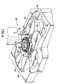
- an incubator assembly 50 capable of replacing the incubator 36 and defined by two vertically stacked incubators 52, 54. These incubators are preferably stacked vertically, substantially one above the other as hereinafter described.
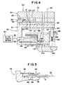
- Each incubator 52, 54, FIG. 4 comprises a rotor assembly 60 and 80, which is independently driven as described below about two offset and substantially vertical axes of rotation 62, 82, FIG. 4.
- the first and second rotor assemblies 60, 80 are disposed in an orientation in which they are substantially parallel to one another and eccentrically mounted relative to the other, thereby defining the offset rotational vertical axes 62 and 82, FIG. 4.
- Each of the rotor assemblies 60, 80 is defined by a rotor 66, 86, having a circular cross section which is mounted for rotation on lower and upper support plates 64, 84, respectively.
- a series of adjacently and evenly spaced stations 68, 88 are disposed about the circumference of each rotor 66, 86.
- the upper rotor 84 according to this embodiment is slightly smaller than the lower rotor 64. As a result, when viewed from above, FIG. 3, the footprint of the upper incubator falls substantially within the footprint of the lower incubator.
- a input or "home” station 76 is provided for the loading of test elements into either rotor assembly.
- An exit chute 72 is also adjacently positioned relative to the home station 76 for disposing of elements which have completed testing, the details of which are commonly known in the field.
- Incubator 52 is conventional and is preferably dedicated to rate type assays. It comprises, as shown in U.S. Patent No. 5,106,586, among others, a rotor 66 that receives at stations 68, a slide test element E from any slide element insert means 90 that moves the slide element in the direction of arrow 92.
- An evaporation cap 94 used to keep sample contained on test element E from prematurely evaporating, is spring-biased by a spring 96, down onto the slide element.
- Spring 96 can be flat, as shown, or a J-spring as in the '586 patent.
- the element E can be read by a reader (not shown) located below the rotor 66 that illuminates element E through an aperture 98.
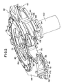
- the lower rotor 66 can have up to 27 stations disposed about its periphery, though FIG. 2 shows a fewer number number of stations for clarity.
- Each station 68, FIG. 2 is actually a slotted region having a pair of guiding shoulders 75, FIG. 2, to retain the element therein as it is biased by the spring 96.
- the lower rotor 66 is mounted for rotation about vertical axis 62 to the lower support plate 64.
- a motor 100 having an output shaft 104 extending through an aperture 103 in the lower support plate 64 is connected in a manner conventionally known to a drive pinion gear 106.
- the output shaft 104 rotates along with the pinion gear 106 which engages a toothed inner periphery (not shown) of the lower rotor 66.
- a ring bearing 102, FIG. 2, situated in a circumferential slot 78, FIG. 2, located between the lower support plate 64 and the rotor 64 allows relatively free rotation of the rotor.
- the upper incubator 54 is preferably dedicated to potentiometric-type slide test elements, such as those available from Eastman Kodak Company under the tradename of "EKTACHEM".
- EKTACHEM potentiometric-type slide test elements
- a preferred construction of such an incubator 54 is that disclosed in US-A-5 340 540. More specifically, the upper incubator 54 comprises a rotor assembly 80 having a number of stations 88 which are evenly spaced about the circumference of rotor 86, each of which is capable of receiving a potentiometric slide element E', covered by an evaporator cap 110 having legs 112, 114, 116 that project through the rotor 86 (omitted in the FIG. 6) to a stationary cam track 120 which is positioned beneath.
- Track 120 has a plurality of rails 122, 124, 126 each designed to act on one of the three legs 112, 114, 116 so that the cap 110 raises and lowers in a uniform fashion, without any significant sideways thrust (arrow 136 is a force less than 1G) caused by one side of the cap 109 coming down before the other side 107. That is, the raised portion of the rail 126 is offset from the raised portions of the rails 122, 124 exactly the distance between leg 112 and leg 114.
- cap 110 thus goes up to allow a slide element E' to be inserted, into a station 86, and then down to cover the liquid-bearing part 200, without a sideways jarring of the element.
- Rotation of the upper rotor 86 about the vertical axis 82, per arrow 137, is achieved in a similar fashion as that of the lower rotor 64; that is by a motor 130 having an output shaft 132 for driving an attached pinion gear 134 which engages the inner toothed periphery 85 of the rotor.
- Rotor 84 is mounted for rotation to the upper support plate 84 by means of a continuous ring bearing (not shown), which is introduced into a slot (not shown) provided in the upper support plate.
- a plurality of bearing shoes can be placed in the slot in lieu of a continuous ring bearing to allow rotation of the upper rotor 86 about the axis 82.
- Elements E' can be loaded onto the rotor 82, and specifically at stations 88, as shown in phantom per arrow 138 by the same slide insert means 90 as is used by the lower incubator 52, see FIG. 4, or by a slide distributor 34, FIG. 1.
- a potentiometric read station (not shown), features a pair of electrodes (not shown) that are raised and lowered into contact with the liquid bearing portions 200 of the element E'. This station is not activated until an ISE test element E' is positioned thereunder, ready for reading, as determined and controlled by a suitable microprocessor, as is conventionally known.
- Upper rotor 86 is smaller in diameter than the lower rotor 66 and is sized to fit up to 15 slide elements E'. Because of the disparity in size between the two rotors, the respective vertical axes of rotation 62, 82 are horizontally offset from each other, as shown schematically in FIG. 2, in order to provide a minimal offset at the "home" position 78. At position 78, as shown in the sectional view of FIG. 2, it can be seen that outside diameters of the two rotor assemblies 60, 80 are literally coincident. In the present embodiment, an offsetting of axis 82 by about 0.866 inches horizontally from axis 62 provides this coincidence, allowing slide elements to be loaded and unloaded more efficiently and conveniently. Hence, the preferred loading and unloading stations are at 92 and 92', FIG. 4. It can be seen that other differently sized rotors can be similarly offset to provide an efficient loading and unloading station.
- the upper support plate 84 has three equally spaced legs 160, 162, and 164, (shown only in FIG. 3), located on exterior portions which downwardly depend for engaging the lower support plate 64.
- Each of the legs 160, 162, 164 have a beveled guiding end portion 166, appropriately sized to fit within a corresponding defined slot 168 in the lower support plate 64.
- the engagement of the legs 160, 162, 164 into the three slots 168 acts to locate the upper and the lower support plates 84, 64 relative to each other.
- two contact surfaces are provided on the lower support plate 64, (of which only one is shown in the FIG.), having upwardly extending engagement pins 170 for mating with a corresponding hole (not shown) and slot 172 which are provided along adjacent legs 164 and 162, respectively, to allow repeatable alignment of the rotor assemblies 60, 80.
- This engagement also provides the spacing between the upper and lower incubators 52, 54, FIG. 4. In this embodiment, the spacing between the upper and lower support plates is approximately 1 inch, through this value can be easily varied.
- Each of the support surfaces are provided with heating elements, such as heating tapes (not shown) which are positioned on the undersurface of the plates.
- the plates 64, 84 being made from a material having a high thermal conductivity, such as aluminum are placed in sufficient contact with the rotors 66, 86 for convective heating to occur, as is conventionally known.
- Covers are provided to cover each of the stacked rotor assemblies 60, 80 so as to provide independent thermally controlled chambers.
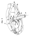
- a lower cover 74, FIGS. 7, 8, is provided to cover the lower incubator 52, while a top cover 70, FIGS. 8, 9, is introduced to cover the upper incubator 54.
- the mounting means compries a connector comprising a vertical shaft 180 fixed to a lift and turn plate 182, the shaft being slideable through a fixed hollow tube 184 extending from the shaft 180.
- a pivot aperture 188 in which a pivot pin (not shown) is inserted.
- the lower cover 74 is then secured to the lift and turn plate 182, using C-shaped guides 192 and 194 fixed to the undersurface of the plate 182.
- the notches cut into guides 192 and 194 mate with the curved exterior edge of the lift and turn plate 182.
- guide 194 has a camming portion 196 which can swing into contact with a cam follower (not shown) to pivot the lower cover 74 horizontally through an angle in order to access lower incubator 52, FIG. 4, wherein rotation is achieved about the pivot pin.
- the shaft 180 is limited to a vertical motion within the tube 184 by a guide pin 186, FIG. 2, which is secured a stationary portion 198 of the incubator which also secures the hollow tube in place.
- the guide pin 186 penetrates a through hole in the tube 184 and rides within a slot (not shown) cut into the side of the shaft 180, FIG. 2.
- a compression spring 190 FIG. 2 is mounted between the shaft 180 and a stationary portion 192, FIG. 2, of the incubator assembly.
- the spring constant of the compression spring 190 is selected so that when the lower cover 74 is completely lowered, FIGS. 4 and 8, it exerts a force about equal to the weight of the lower cover, as well as the upper incubator, FIG. 4. Additional details of the raising cover assembly are provided in the raising mechanism Application cross-referenced previously.
- a lockdown assembly 250 is screwed through that cover into the lower incubator Plate 64, FIG. 4.
- the lockdown assembly 250 is engaged through the center of the upper incubator assembly and, Plate 84, FIG. 4, and comprises a rotatable knob 252 which is seated to a knob tower 254 having an engagement aperture 255 sized to fit a collar 256.
- the fitted collar 256 engages with one end of an inserted member 260 which is positioned upwardly through a central through opening 261 in the knob tower 254.
- the inserted member 260 has a flange 262, which is sized larger than the opening 261 in the knob tower 254 to restrict further upward movement when inserted into the opening, as well as an adjacent threaded bottom portion 264 at the other end of the inserted member.
- the threaded bottom portion 264 is fitted into engagement holes provided in the lift and turn plate 182 and the lower support plate 64, as shown.
- the opening 261 in the knob tower 254 is adequately sized to fit the inserted member 260, having a recessed portion sized to additionally accommodate a compression spring 268 as well as the collar 256.
- the collar 256 When fully assembled according to FIG. 8, the collar 256 bears against the spring 268 to provide a biasing force to allow threading of the bottom portion 264 of inserted member 260 so as to engage the lift and turn plate 182 and the lower support plate 64. In so doing, a locked position is achieved which overcomes the spring force provided by the lower cover raising assembly.
- the rotatable knob 252 extends above the top cover 70.
- the top cover 70 can be separately removed without having to engage or otherwise disrupt the lower cover raising mechanism.
- the latch mechanism 220 consists of a single locking pin or fastener 222 which engages corresponding apertures 223, 224 located in the top cover 70 and the upper support plate 84, respectively.
- a receiving means is provided for locking the fastener 222 after its insertion into the aperture 224.
- a 1/4 turn fastener is used as are commonly known.
- the top cover 70 has a central aperture 270 sized to allow the cover to be raised separately about the hinged portion 210, as shown in phantom in FIG. 9, without interfering with the lockdown assembly 250. In use, a one quarter turn of the locking fastener 222 engages or disengages the fastener from the upper support plate 84 to allow the top cover 70 to be separately locked or raised as shown.
- the incubator assembly 50 is disposed within an analyzer 20, such as the one shown in FIG. 1, for example, those manufactured by Eastman Kodak Company under the tradename of EKTACHEM.
- Each of the slide elements E and E' can be conveniently loaded and unloaded at the stations 92 and 92' into and out of either of any convenient slide moving means.
- an elevator (not shown) can be positioned adjacent the lower or upper rotor assemblies 60, 80.
- the elevator which mounts to attachment detail (not shown) provided on the incubator assembly 50 at home station 78 is described in greater details in a copending European patent application filed on the same date as the present application (Representative's ref: P13710EP, claiming priority from USSN 08/236 908).
- the incubator assembly of the present invention can have multiple incubators arranged other than that described.
- a plurality of incubators could be vertically arranged from one another in either a stacked, a staggered or other configuration.
Landscapes
- General Health & Medical Sciences (AREA)
- Physics & Mathematics (AREA)
- Life Sciences & Earth Sciences (AREA)
- Chemical & Material Sciences (AREA)
- Analytical Chemistry (AREA)
- Biochemistry (AREA)
- Immunology (AREA)
- General Physics & Mathematics (AREA)
- Health & Medical Sciences (AREA)
- Pathology (AREA)
- Automatic Analysis And Handling Materials Therefor (AREA)
- Apparatus Associated With Microorganisms And Enzymes (AREA)
- Accommodation For Nursing Or Treatment Tables (AREA)
- Investigating Or Analysing Biological Materials (AREA)
Applications Claiming Priority (2)
| Application Number | Priority Date | Filing Date | Title |
|---|---|---|---|
| US235041 | 1994-04-29 | ||
| US08/235,041 US5523056A (en) | 1994-04-29 | 1994-04-29 | Twin rotor incubator assembly |
Publications (2)
| Publication Number | Publication Date |
|---|---|
| EP0679894A1 true EP0679894A1 (fr) | 1995-11-02 |
| EP0679894B1 EP0679894B1 (fr) | 2000-03-15 |
Family
ID=22883841
Family Applications (1)
| Application Number | Title | Priority Date | Filing Date |
|---|---|---|---|
| EP95302918A Expired - Lifetime EP0679894B1 (fr) | 1994-04-29 | 1995-04-28 | Dispositif d'incubation à double rotor |
Country Status (5)
| Country | Link |
|---|---|
| US (1) | US5523056A (fr) |
| EP (1) | EP0679894B1 (fr) |
| JP (1) | JPH0882628A (fr) |
| AT (1) | ATE190729T1 (fr) |
| DE (1) | DE69515547T2 (fr) |
Families Citing this family (22)
| Publication number | Priority date | Publication date | Assignee | Title |
|---|---|---|---|---|
| US20040191128A1 (en) * | 1992-05-11 | 2004-09-30 | Cytologix Corporation | Slide stainer with heating |
| US6180061B1 (en) | 1992-05-11 | 2001-01-30 | Cytologix Corporation | Moving platform slide stainer with heating elements |
| ATE317112T1 (de) * | 1996-09-18 | 2006-02-15 | Tiyoda Seisakusho Kk | Flüssigkeitsbehandlungsvorrichtung fur biologische proben |
| US6183693B1 (en) * | 1998-02-27 | 2001-02-06 | Cytologix Corporation | Random access slide stainer with independent slide heating regulation |
| US6582962B1 (en) * | 1998-02-27 | 2003-06-24 | Ventana Medical Systems, Inc. | Automated molecular pathology apparatus having independent slide heaters |
| ES2354598T3 (es) | 1998-02-27 | 2011-03-16 | Ventana Medical Systems, Inc. | Aparato de patología molecular automatizado que tiene calefactores de portaobjetos independientes. |
| US7312084B2 (en) * | 2001-07-13 | 2007-12-25 | Ortho-Clinical Diagnostics, Inc. | Tandem incubator for clinical analyzer |
| US7425306B1 (en) | 2001-09-11 | 2008-09-16 | Ventana Medical Systems, Inc. | Slide heater |
| US7270785B1 (en) * | 2001-11-02 | 2007-09-18 | Ventana Medical Systems, Inc. | Automated molecular pathology apparatus having fixed slide platforms |
| US11249095B2 (en) | 2002-04-15 | 2022-02-15 | Ventana Medical Systems, Inc. | Automated high volume slide processing system |
| US7468161B2 (en) | 2002-04-15 | 2008-12-23 | Ventana Medical Systems, Inc. | Automated high volume slide processing system |
| DK1890127T3 (da) | 2002-04-15 | 2013-09-23 | Ventana Med Syst Inc | Automatiseret objektglasfarvningssystem med høj kapacitet |
| ES2556242T3 (es) * | 2002-04-26 | 2016-01-14 | Ventana Medical Systems, Inc. | Aparato de patología molecular automatizado que tiene plataformas de portaobjetos fijas |
| JP3638931B2 (ja) * | 2002-10-31 | 2005-04-13 | 照明 伊藤 | 検体遠心分離システム |
| JP3675799B2 (ja) * | 2003-01-31 | 2005-07-27 | 照明 伊藤 | 検体遠心分離システム |
| US20040191923A1 (en) * | 2003-03-31 | 2004-09-30 | Tomasso David Angelo | Test element holder with a probe guide for an analyzer |
| US7597847B2 (en) * | 2003-03-31 | 2009-10-06 | Ortho-Clinical Diagnostics, Inc. | Analyzer having a stationary multifunction probe |
| US8043562B2 (en) * | 2003-12-08 | 2011-10-25 | Ortho-Clinical Diagnostics, Inc. | Analyzer having removable holders or a centrifuge |
| EP1697719B1 (fr) | 2003-12-23 | 2018-09-19 | Ventana Medical Systems, Inc. | Procede et appareil de traitement efficace faisant intervenir un liquide dans une couche mince de surfaces plates |
| CN102209889B (zh) | 2008-11-12 | 2015-05-13 | 文塔纳医疗系统公司 | 用于加热载持标本的载玻片的方法及设备 |
| CN105793690B (zh) | 2013-12-13 | 2020-01-03 | 文塔纳医疗系统公司 | 生物样本的自动化组织学处理及相关的技术 |
| US10031085B2 (en) | 2014-07-24 | 2018-07-24 | Ortho-Clinical Diagnostics, Inc. | Point of care analytical processing system |
Citations (2)
| Publication number | Priority date | Publication date | Assignee | Title |
|---|---|---|---|---|
| US3489521A (en) * | 1965-04-14 | 1970-01-13 | Vickers Ltd | Automatic laboratory |
| EP0576291A2 (fr) * | 1992-06-26 | 1993-12-29 | Bio-Rad Laboratories, Inc. | Analyseur clinique automatisé avec régulation de température |
Family Cites Families (14)
| Publication number | Priority date | Publication date | Assignee | Title |
|---|---|---|---|---|
| US3912452A (en) * | 1973-12-13 | 1975-10-14 | Damon Corp | Method and apparatus for photometric analysis of liquid samples |
| US4298571A (en) * | 1976-12-17 | 1981-11-03 | Eastman Kodak Company | Incubator including cover means for an analysis slide |
| US4296069A (en) * | 1980-06-16 | 1981-10-20 | Eastman Kodak Company | Apparatus for processing an analysis slide |
| US4512952A (en) * | 1982-07-01 | 1985-04-23 | Eastman Kodak Company | Apparatus for storing and dispensing analysis slides |
| US4568519A (en) * | 1983-06-29 | 1986-02-04 | Eastman Kodak Company | Apparatus for processing analysis slides |
| DE3683573D1 (de) * | 1985-06-26 | 1992-03-05 | Japan Tectron Instr Corp | Automatischer analysenapparat. |
| US5051238A (en) * | 1987-11-20 | 1991-09-24 | Hitachi, Ltd. | Automatic analyzing system |
| US5229074A (en) * | 1988-07-25 | 1993-07-20 | Precision Systems, Inc. | Automatic multiple-sample multiple-reagent chemical analyzer |
| US5073342A (en) * | 1989-01-05 | 1991-12-17 | Eastman Kodak Company | Reciprocating transfer mechanism |
| US5034191A (en) * | 1989-01-05 | 1991-07-23 | Eastman Kodak Company | Incubator and analyzer with improved cap raising means |
| US4963333A (en) * | 1989-05-02 | 1990-10-16 | Eastman Kodak Company | Universal evaporation cover |
| US5075079A (en) * | 1990-05-21 | 1991-12-24 | Technicon Instruments Corporation | Slide analysis system |
| US5106586A (en) * | 1990-05-23 | 1992-04-21 | Eastman Kodak Company | J-shaped spring used in incubator |
| US5196168A (en) * | 1991-12-19 | 1993-03-23 | Eastman Kodak Company | Incubator with positioning device for slide elements |
-
1994
- 1994-04-29 US US08/235,041 patent/US5523056A/en not_active Expired - Fee Related
-
1995
- 1995-04-28 DE DE69515547T patent/DE69515547T2/de not_active Expired - Fee Related
- 1995-04-28 EP EP95302918A patent/EP0679894B1/fr not_active Expired - Lifetime
- 1995-04-28 AT AT95302918T patent/ATE190729T1/de not_active IP Right Cessation
- 1995-05-01 JP JP7107630A patent/JPH0882628A/ja active Pending
Patent Citations (2)
| Publication number | Priority date | Publication date | Assignee | Title |
|---|---|---|---|---|
| US3489521A (en) * | 1965-04-14 | 1970-01-13 | Vickers Ltd | Automatic laboratory |
| EP0576291A2 (fr) * | 1992-06-26 | 1993-12-29 | Bio-Rad Laboratories, Inc. | Analyseur clinique automatisé avec régulation de température |
Non-Patent Citations (1)
| Title |
|---|
| ANONYMOUS: "Analyzer for washing rate slides using movable wash enclosure operated between two incubators", RESEARCH DISCLOSURE, no. 338, EMSWORTH GB, pages 472 - 481 * |
Also Published As
| Publication number | Publication date |
|---|---|
| US5523056A (en) | 1996-06-04 |
| DE69515547D1 (de) | 2000-04-20 |
| EP0679894B1 (fr) | 2000-03-15 |
| DE69515547T2 (de) | 2000-07-20 |
| JPH0882628A (ja) | 1996-03-26 |
| ATE190729T1 (de) | 2000-04-15 |
Similar Documents
| Publication | Publication Date | Title |
|---|---|---|
| EP0679894B1 (fr) | Dispositif d'incubation à double rotor | |
| AU726007B2 (en) | Incubation station for test sample cards | |
| US5419871A (en) | Analyzer elevator assembly | |
| EP0712000B1 (fr) | Disposif d'incubation | |
| US4676952A (en) | Photometric analysis apparatus for a liquid | |
| EP0703457B1 (fr) | Appareil d'analyse | |
| EP1681569B1 (fr) | Analyseur de diagnostic de test d'analyse | |
| KR0168659B1 (ko) | 인큐베이터에 중심이 잡힌 카트리지의 원형 트랙을 특징으로하는 분석기 및 그 사용방법 | |
| US9108832B2 (en) | Cover opener and automatic analyzing device using same | |
| EP1402272B1 (fr) | Incubateur en tandem pour analyseur clinique | |
| US6106781A (en) | Conveying system for analytical samples | |
| US5089418A (en) | Analyzer featuring a circular track of cartridges centered on an incubator and method of use | |
| CA2036161A1 (fr) | Systeme d'analyse a lames | |
| US20050123444A1 (en) | Analyzer having removable holders or a centrifuge | |
| US5738827A (en) | Apparatus for holding reagent and sample vessels | |
| AU2002346018A1 (en) | Multiple track incubator for clinical analyzer | |
| CA2462484A1 (fr) | Analyseur a sonde multifonctions fixe | |
| US5518693A (en) | Transfer mechanism for automatic loading and unloading of reagent modules | |
| EP0632271B1 (fr) | Dispositif de transfert pour le chargement et déchargement automatique de modules de réactifs | |
| EP0571033B1 (fr) | Dispositif d'incubation | |
| EP0679896B1 (fr) | Mécanisme de levage d'un couvercle d'incubateur | |
| JP3853741B2 (ja) | インキュベータ |
Legal Events
| Date | Code | Title | Description |
|---|---|---|---|
| PUAI | Public reference made under article 153(3) epc to a published international application that has entered the european phase |
Free format text: ORIGINAL CODE: 0009012 |
|
| AK | Designated contracting states |
Kind code of ref document: A1 Designated state(s): AT BE CH DE DK FR GB IT LI NL SE |
|
| 17P | Request for examination filed |
Effective date: 19960410 |
|
| 17Q | First examination report despatched |
Effective date: 19981207 |
|
| GRAG | Despatch of communication of intention to grant |
Free format text: ORIGINAL CODE: EPIDOS AGRA |
|
| GRAG | Despatch of communication of intention to grant |
Free format text: ORIGINAL CODE: EPIDOS AGRA |
|
| GRAH | Despatch of communication of intention to grant a patent |
Free format text: ORIGINAL CODE: EPIDOS IGRA |
|
| GRAH | Despatch of communication of intention to grant a patent |
Free format text: ORIGINAL CODE: EPIDOS IGRA |
|
| GRAA | (expected) grant |
Free format text: ORIGINAL CODE: 0009210 |
|
| AK | Designated contracting states |
Kind code of ref document: B1 Designated state(s): AT BE CH DE DK FR GB IT LI NL SE |
|
| PG25 | Lapsed in a contracting state [announced via postgrant information from national office to epo] |
Ref country code: SE Free format text: THE PATENT HAS BEEN ANNULLED BY A DECISION OF A NATIONAL AUTHORITY Effective date: 20000315 Ref country code: NL Free format text: LAPSE BECAUSE OF FAILURE TO SUBMIT A TRANSLATION OF THE DESCRIPTION OR TO PAY THE FEE WITHIN THE PRESCRIBED TIME-LIMIT Effective date: 20000315 Ref country code: IT Free format text: LAPSE BECAUSE OF FAILURE TO SUBMIT A TRANSLATION OF THE DESCRIPTION OR TO PAY THE FEE WITHIN THE PRESCRIBED TIME-LIMIT;WARNING: LAPSES OF ITALIAN PATENTS WITH EFFECTIVE DATE BEFORE 2007 MAY HAVE OCCURRED AT ANY TIME BEFORE 2007. THE CORRECT EFFECTIVE DATE MAY BE DIFFERENT FROM THE ONE RECORDED. Effective date: 20000315 Ref country code: BE Free format text: LAPSE BECAUSE OF FAILURE TO SUBMIT A TRANSLATION OF THE DESCRIPTION OR TO PAY THE FEE WITHIN THE PRESCRIBED TIME-LIMIT Effective date: 20000315 Ref country code: AT Free format text: LAPSE BECAUSE OF FAILURE TO SUBMIT A TRANSLATION OF THE DESCRIPTION OR TO PAY THE FEE WITHIN THE PRESCRIBED TIME-LIMIT Effective date: 20000315 |
|
| REF | Corresponds to: |
Ref document number: 190729 Country of ref document: AT Date of ref document: 20000415 Kind code of ref document: T |
|
| REG | Reference to a national code |
Ref country code: CH Ref legal event code: NV Representative=s name: E. BLUM & CO. PATENTANWAELTE Ref country code: CH Ref legal event code: EP |
|
| REF | Corresponds to: |
Ref document number: 69515547 Country of ref document: DE Date of ref document: 20000420 |
|
| ET | Fr: translation filed | ||
| PG25 | Lapsed in a contracting state [announced via postgrant information from national office to epo] |
Ref country code: DK Free format text: LAPSE BECAUSE OF FAILURE TO SUBMIT A TRANSLATION OF THE DESCRIPTION OR TO PAY THE FEE WITHIN THE PRESCRIBED TIME-LIMIT Effective date: 20000615 |
|
| NLV1 | Nl: lapsed or annulled due to failure to fulfill the requirements of art. 29p and 29m of the patents act | ||
| PLBE | No opposition filed within time limit |
Free format text: ORIGINAL CODE: 0009261 |
|
| STAA | Information on the status of an ep patent application or granted ep patent |
Free format text: STATUS: NO OPPOSITION FILED WITHIN TIME LIMIT |
|
| 26N | No opposition filed | ||
| PGFP | Annual fee paid to national office [announced via postgrant information from national office to epo] |
Ref country code: FR Payment date: 20010409 Year of fee payment: 7 |
|
| PGFP | Annual fee paid to national office [announced via postgrant information from national office to epo] |
Ref country code: DE Payment date: 20010423 Year of fee payment: 7 |
|
| PGFP | Annual fee paid to national office [announced via postgrant information from national office to epo] |
Ref country code: GB Payment date: 20010425 Year of fee payment: 7 |
|
| PGFP | Annual fee paid to national office [announced via postgrant information from national office to epo] |
Ref country code: CH Payment date: 20010502 Year of fee payment: 7 |
|
| REG | Reference to a national code |
Ref country code: GB Ref legal event code: IF02 |
|
| PG25 | Lapsed in a contracting state [announced via postgrant information from national office to epo] |
Ref country code: GB Free format text: LAPSE BECAUSE OF NON-PAYMENT OF DUE FEES Effective date: 20020428 |
|
| PG25 | Lapsed in a contracting state [announced via postgrant information from national office to epo] |
Ref country code: LI Free format text: LAPSE BECAUSE OF NON-PAYMENT OF DUE FEES Effective date: 20020430 Ref country code: CH Free format text: LAPSE BECAUSE OF NON-PAYMENT OF DUE FEES Effective date: 20020430 |
|
| PG25 | Lapsed in a contracting state [announced via postgrant information from national office to epo] |
Ref country code: DE Free format text: LAPSE BECAUSE OF NON-PAYMENT OF DUE FEES Effective date: 20021101 |
|
| REG | Reference to a national code |
Ref country code: CH Ref legal event code: PL |
|
| GBPC | Gb: european patent ceased through non-payment of renewal fee |
Effective date: 20020428 |
|
| PG25 | Lapsed in a contracting state [announced via postgrant information from national office to epo] |
Ref country code: FR Free format text: LAPSE BECAUSE OF NON-PAYMENT OF DUE FEES Effective date: 20021231 |
|
| REG | Reference to a national code |
Ref country code: FR Ref legal event code: ST |