EP0680805A2 - Machine de coupage au laser avec réglage de la position focale - Google Patents
Machine de coupage au laser avec réglage de la position focale Download PDFInfo
- Publication number
- EP0680805A2 EP0680805A2 EP95105090A EP95105090A EP0680805A2 EP 0680805 A2 EP0680805 A2 EP 0680805A2 EP 95105090 A EP95105090 A EP 95105090A EP 95105090 A EP95105090 A EP 95105090A EP 0680805 A2 EP0680805 A2 EP 0680805A2
- Authority
- EP
- European Patent Office
- Prior art keywords
- laser cutting
- laser
- workpiece
- cutting machine
- cutting head
- Prior art date
- Legal status (The legal status is an assumption and is not a legal conclusion. Google has not performed a legal analysis and makes no representation as to the accuracy of the status listed.)
- Granted
Links
Images


Classifications
-
- B—PERFORMING OPERATIONS; TRANSPORTING
- B23—MACHINE TOOLS; METAL-WORKING NOT OTHERWISE PROVIDED FOR
- B23K—SOLDERING OR UNSOLDERING; WELDING; CLADDING OR PLATING BY SOLDERING OR WELDING; CUTTING BY APPLYING HEAT LOCALLY, e.g. FLAME CUTTING; WORKING BY LASER BEAM
- B23K26/00—Working by laser beam, e.g. welding, cutting or boring
- B23K26/02—Positioning or observing the workpiece, e.g. with respect to the point of impact; Aligning, aiming or focusing the laser beam
- B23K26/04—Automatically aligning, aiming or focusing the laser beam, e.g. using the back-scattered light
- B23K26/046—Automatically focusing the laser beam
-
- B—PERFORMING OPERATIONS; TRANSPORTING
- B23—MACHINE TOOLS; METAL-WORKING NOT OTHERWISE PROVIDED FOR
- B23K—SOLDERING OR UNSOLDERING; WELDING; CLADDING OR PLATING BY SOLDERING OR WELDING; CUTTING BY APPLYING HEAT LOCALLY, e.g. FLAME CUTTING; WORKING BY LASER BEAM
- B23K26/00—Working by laser beam, e.g. welding, cutting or boring
- B23K26/02—Positioning or observing the workpiece, e.g. with respect to the point of impact; Aligning, aiming or focusing the laser beam
- B23K26/06—Shaping the laser beam, e.g. by masks or multi-focusing
- B23K26/064—Shaping the laser beam, e.g. by masks or multi-focusing by means of optical elements, e.g. lenses, mirrors or prisms
- B23K26/0643—Shaping the laser beam, e.g. by masks or multi-focusing by means of optical elements, e.g. lenses, mirrors or prisms comprising mirrors
-
- B—PERFORMING OPERATIONS; TRANSPORTING
- B23—MACHINE TOOLS; METAL-WORKING NOT OTHERWISE PROVIDED FOR
- B23K—SOLDERING OR UNSOLDERING; WELDING; CLADDING OR PLATING BY SOLDERING OR WELDING; CUTTING BY APPLYING HEAT LOCALLY, e.g. FLAME CUTTING; WORKING BY LASER BEAM
- B23K26/00—Working by laser beam, e.g. welding, cutting or boring
- B23K26/02—Positioning or observing the workpiece, e.g. with respect to the point of impact; Aligning, aiming or focusing the laser beam
- B23K26/06—Shaping the laser beam, e.g. by masks or multi-focusing
- B23K26/064—Shaping the laser beam, e.g. by masks or multi-focusing by means of optical elements, e.g. lenses, mirrors or prisms
- B23K26/0648—Shaping the laser beam, e.g. by masks or multi-focusing by means of optical elements, e.g. lenses, mirrors or prisms comprising lenses
-
- B—PERFORMING OPERATIONS; TRANSPORTING
- B23—MACHINE TOOLS; METAL-WORKING NOT OTHERWISE PROVIDED FOR
- B23K—SOLDERING OR UNSOLDERING; WELDING; CLADDING OR PLATING BY SOLDERING OR WELDING; CUTTING BY APPLYING HEAT LOCALLY, e.g. FLAME CUTTING; WORKING BY LASER BEAM
- B23K26/00—Working by laser beam, e.g. welding, cutting or boring
- B23K26/02—Positioning or observing the workpiece, e.g. with respect to the point of impact; Aligning, aiming or focusing the laser beam
- B23K26/06—Shaping the laser beam, e.g. by masks or multi-focusing
- B23K26/0665—Shaping the laser beam, e.g. by masks or multi-focusing by beam condensation on the workpiece, e.g. for focusing
-
- B—PERFORMING OPERATIONS; TRANSPORTING
- B23—MACHINE TOOLS; METAL-WORKING NOT OTHERWISE PROVIDED FOR
- B23K—SOLDERING OR UNSOLDERING; WELDING; CLADDING OR PLATING BY SOLDERING OR WELDING; CUTTING BY APPLYING HEAT LOCALLY, e.g. FLAME CUTTING; WORKING BY LASER BEAM
- B23K26/00—Working by laser beam, e.g. welding, cutting or boring
- B23K26/12—Working by laser beam, e.g. welding, cutting or boring in a special environment or atmosphere, e.g. in an enclosure
- B23K26/123—Working by laser beam, e.g. welding, cutting or boring in a special environment or atmosphere, e.g. in an enclosure in an atmosphere of particular gases
-
- B—PERFORMING OPERATIONS; TRANSPORTING
- B23—MACHINE TOOLS; METAL-WORKING NOT OTHERWISE PROVIDED FOR
- B23K—SOLDERING OR UNSOLDERING; WELDING; CLADDING OR PLATING BY SOLDERING OR WELDING; CUTTING BY APPLYING HEAT LOCALLY, e.g. FLAME CUTTING; WORKING BY LASER BEAM
- B23K26/00—Working by laser beam, e.g. welding, cutting or boring
- B23K26/14—Working by laser beam, e.g. welding, cutting or boring using a fluid stream, e.g. a jet of gas, in conjunction with the laser beam; Nozzles therefor
- B23K26/1435—Working by laser beam, e.g. welding, cutting or boring using a fluid stream, e.g. a jet of gas, in conjunction with the laser beam; Nozzles therefor involving specially adapted flow-control means
Definitions
- the invention relates to a laser cutting machine with a laser generator and with a laser cutting head which can be displaced in a plane essentially parallel to the workpiece by means of a drive controlled by a numerical control relative to the laser generator and / or relative to a workpiece to be machined, and a focusing optics for the laser beam and an adjusting device for adjusting the focus position of the laser beam by shifting the focus relative to the laser cutting head has substantially perpendicular to the workpiece.
- the laser beam On laser cutting machines with so-called “flying optics", in which the laser cutting head with the focusing optics for the laser beam is moved relative to the workpiece that is stationary during processing, the laser beam has constantly changing path lengths from the laser generator to that due to the constant change in position of the laser cutting head Put the focusing optics back on the laser cutting head.
- the laser beam length is, among other things, decisive for the position of the laser beam focus generated by the focusing optics perpendicular to the workpiece to be machined.
- the entire laser cutting head is known to be raised or lowered depending on the laser beam length in laser cutting machines. The position of the focus remains unchanged relative to the laser cutting head.
- the laser cutting head uses a known experimental setup, developed into a generic laser cutting machine, of an adjusting device for optically adjusting the focus position in the form of adaptive spherical deflection mirrors for the laser beam, which are connected upstream of the focusing optics of the laser cutting head in the direction of the laser beam.
- an adjusting device for optically adjusting the focus position in the form of adaptive spherical deflection mirrors for the laser beam, which are connected upstream of the focusing optics of the laser cutting head in the direction of the laser beam.
- the laser beam geometry changes as a result of a change in the position of the laser cutting head and a change in the beam length associated with this, this change in geometry can be compensated for by varying the mirror curvature.
- the position of the focus generated by the focusing optics perpendicular to the workpiece consequently remains unchanged regardless of the length of the laser beam.
- the invention is based on the object of providing a laser cutting machine which is functional under workshop conditions and is suitable for automated operation and which permits a functionally reliable optical adjustment of the focus position.
- the numerical control for maintaining a constant focus position perpendicular to the workpiece additionally controls the adjusting device for adjusting the focus position depending on the position of the laser cutting head in its plane of movement parallel to the workpiece.
- the position of the laser cutting head representative of the length of the laser beam is first detected by means of the numerical control.
- Each position of the laser cutting head and thus each laser beam length is assigned a specific setting of the adjusting device for varying the focus position. Controlled by the numerical control, the actuating device is brought into the respective target setting.
- the laser cutting head can be displaced within a movement area divided into at least two partial areas and that each partial area is assigned an adjustment value for setting a constant focus position.
- the number of sub-areas is expediently chosen as a function of the size of the area that is coated with the laser cutting head during the machining process.
- the numerical control controls the adjustment of the adjusting device for the focus position. An adjustment of the actuating device is always initiated when the laser cutting head changes from a partial area of its range of motion to a partial area adjacent to it.
- a further embodiment of the invention in which the adjusting device for adjusting the focus position has at least one deflection mirror for the laser beam upstream of the focusing optics in the direction of the laser beam, which is acted upon by a fluid under variable pressure on the surface facing away from its mirror surface and is thereby adaptively curved, is characterized in that the deflecting mirror is acted upon by an adjustable throttle arrangement with which the pressure of the fluid can be changed and that the numerical control of the detected position of the laser cutting head as an adjustment value for adjusting the focus position assigns a setpoint value for the pressure of the fluid and controls the adjustable throttle arrangement to set this setpoint.
- the pressure of the fluid present at its outlet side is regulated.
- the mirror surface of the deflection mirror located downstream of the throttle arrangement can be subjected to variable pressures and its curvature can be changed.
- the convergence or divergence of the laser beam reflected by the deflecting mirror onto the focusing optics and from this focused onto the workpiece depends on the curvature of the mirror surface.
- the adjusting device for the optical adjustment of the focus position is controlled via the adjustment value in such a way that a uniform focus position is set in relation to the workpiece over the entire movement range in its plane of movement parallel to the workpiece to be machined.
- a corresponding target value for the pressure of the fluid is assigned to the partial areas with approximately the same length of the laser beam from the laser generator to the laser cutting head, and that a parallel connection of throttle valves is provided as the throttle arrangement, the number of which corresponds to the number of different setpoints for the pressure of the fluid.
- the numerical controller controls the individual throttle valves of the throttle arrangement on the basis of the adjustment value assigned to the relevant partial area.
- the number of throttle valves switched to the open position is changed via the numerical control.
- the flow cross-section of the throttle arrangement and thereby the pressure of the fluid which is present on its output side and determines the curvature of the mirror surface of the deflecting mirror is set to the desired value.
- the pressure of the fluid which is established on the output side of the throttle arrangement when the other throttle valves of the throttle arrangement are switched to the closed position and only the permanently open throttle valve is flowed through by fluid corresponds to a pressure setpoint value assigned to a partial area of the laser cutting head movement.
- a laser cutting machine of the type mentioned at the outset the focusing optics on the laser cutting head are guided so as to be displaceable essentially perpendicular to the workpiece by means of a feed motor.
- a laser cutting machine is characterized by a functionally reliable optical adjustment of the focus position. A change in the focus position due to a change in position of the laser cutting head and a change in the laser beam length associated therewith can be avoided by shifting the focusing optics.
- the housing of the laser cutting head with the components provided, such as the nozzle for feeding cutting gas into the cutting track of the laser beam can maintain its set distance from the workpiece throughout the machining process.
- the mass to be moved when setting the focus position is accordingly minimal;
- the constant distance of the nozzle from the workpiece, together with the focus position that remains constant over the entire range of motion of the laser cutting head, ensures a uniform cutting quality.
- an electric stepping motor is provided as the feed motor.
- a piston-cylinder arrangement is recommended as the feed motor.
- the adjusting device for adjusting the focal position has at least one lens system with adjustable focal length upstream of the focusing optics in the direction of the laser beam.
- the lens system advantageously has at least one converging lens and at least one diverging lens, which are arranged one behind the other in the direction of the laser beam and can be displaced relative to one another in order to adjust the focal length.
- the focal length of the lens system and thus the convergence or divergence of the laser beam impinging on the focusing optics can be varied by an easily controllable movement, namely by a linear relative displacement of the converging lens and the diverging lens in the axial direction of the laser beam. Automated, time-optimized operation of such a laser cutting machine is ensured if the focal length of the lens system is controlled by the numerical control.
- the focus position is adjusted by means of the numerical control of the laser cutting machine according to the principle as explained above for laser cutting machines according to the invention with adaptive deflecting mirrors.
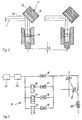
- a laser beam 1 is directed from a laser generator 2 via deflecting mirrors 3, 4, 5, 6, 7 to a focusing optics designed as a converging lens 8.
- the converging lens 8 bundles the laser beam 1 through a nozzle 9 onto a workpiece, not shown.
- the nozzle 9 serves to feed cutting gas into the cutting track of the laser beam 1.
- the deflecting mirror 7 is an adaptive mirror with a variable curvature.
- the laser generator 2 and the deflecting mirrors 3 and 4 are installed in a fixed position on the machine frame of the laser cutting machine.
- a laser cutting head 10 is slidably guided on the machine frame, on the outside of which the deflecting mirror 6 is attached and which receives the deflecting mirror 7 as well as the converging lens 8 and the nozzle 9.
- the laser cutting head 10 has a three-axis range of motion. In a horizontal plane it can be moved in the direction of an x-axis and a y-axis. In addition, the laser cutting head 10 can be raised and lowered in the direction of a z-axis. Below the laser cutting head (10), the range of motion divided into four sub-areas is indicated.
- a change in position of the laser cutting head 10 is associated with a change in the path length that the laser beam 1 has to travel from the laser generator 2 to the converging lens 8.
- a change in the length of the laser beam 1 a change in the position of the focus, to which the converging lens 8 focuses the laser beam 1, is perpendicular in one direction connected to the workpiece, not shown.
- Such a change in the focus position during the cutting process causes changes in the cutting quality or the cutting data.
- the focus whose distance from the converging lens 8 remains unchanged, can be raised or lowered as required by the movement of the laser cutting head 10 in the z direction, and can thus be kept at a uniform level with respect to the workpiece. If the laser cutting head 10 is raised or lowered, the nozzle 9 moves with it, so that the distance between the lower edge of the nozzle and the upper edge of the workpiece frequently changes during the machining process. This distance must be kept as constant as the focus position in order to obtain similar cutting conditions over the entire machining area.
- a constant distance between the nozzle and the workpiece is ensured in the devices for focus position adjustment shown in FIGS. 2, 5a, 5b and 6. These devices make it possible to guide the laser cutting head 10 over the workpiece to be machined at a constant distance in the direction of the z-axis.
- the device according to FIG. 1 uses the adaptive mirror 7 for this purpose.
- the adaptive mirror 7 has a polished mirror surface 12 which is formed by the surface of a thin metal disk. This thin metal disk is clamped with its edges in the mounting ring of a mirror housing 13.
- the incident laser beam 1 is reflected by the mirror surface 12 to a converging lens 8, which bundles the laser beam 1 onto the workpiece surface.
- pressurized water is applied to the metal disk of the mirror via a fluid line 14. Since the metal disc of the mirror 7 shown has been made flat at a pressure of 1.25 bar, the mirror surface 12 has a flat profile when pressurized water is present in the fluid line 14 at a pressure of 1.25 bar. If the pressure in the fluid line 14 drops below this value, the mirror surface 12 assumes a concave shape, as is shown in the right part of FIG. 2. Accordingly, an increase in the pressure in the fluid line 14 above 1.25 bar leads to a convex deformation of the mirror surface 12. The degree of convexity or concavity of the mirror surface 12 can be adjusted by controlling the pressure in the fluid line 14.
- a change in the curvature of the mirror surface 12 leads to a change in the convergence or divergence of the laser beam 1 reflected by the mirror surface 12, depending on the geometry of the laser beam that arises 1.
- the position of the focus of the laser beam 1 generated by the converging lens 8 varies perpendicular to the workpiece.
- the pressure in the fluid line 14 is set using the numerical control of the laser cutting machine. This is connected to a throttle arrangement 15, as shown in FIG 3 is shown.
- the throttle arrangement 15 is upstream of the adaptive mirror 7 in the direction of flow of the pressurized water and comprises four throttle valves 16, 17, 18, 19 connected in parallel.
- the throttle valve 16 is permanently flowed through by pressurized water.
- the flow of pressurized water through the throttle valves 17, 18, 19 can be blocked or released by controllable solenoid valves 20, 21, 22.
- a fixed throttle 23 is provided in the return of the pressurized water; a pressure regulator 24 and a fine filter 25 are connected upstream of the throttle arrangement 15.
- the pressurized water provided by a pressure source is fed to the throttle arrangement 15 via the fine filter 25 and the pressure regulator 24.
- a maximum system pressure is specified by means of the pressure regulator 24. Since the fixed throttle 23 has a constant flow cross section and consequently builds up a constant dynamic pressure, the pressure prevailing in the fluid line 14 of the adaptive mirror 7 can be adjusted by controlling the throttle arrangement 15. Since the throttle valve 16 is permanently flowed through by pressurized water, the adaptive mirror 7 and the deflecting mirror 6 connected downstream of it are always supplied with a certain amount of pressurized water acting as a coolant. In the embodiment shown, when the solenoid valves 20, 21, 22 are closed, a pressure of 0.5 bar is present on the output side of the throttle arrangement 15 and thus also on the rear of the mirror surface 12 of the adaptive mirror 11.
- a range of motion swept by the relevant laser cutting head is in the horizontal xy plane divided into a total of fifteen fields.
- the hatched fields form subregions I, II, III, IV of the movement range of the laser cutting head, within which the length of the laser beam changes only slightly from the laser generator to the laser cutting head when the laser cutting head moves parallel to the workpiece. Accordingly, a change in position of the laser cutting head within the partial areas I, II, III, IV does not lead to a significant change in the focus position of the laser beam perpendicular to the workpiece. An adjustment of the focus position is necessary, however, when the laser cutting head changes from a partial area to a partial area adjacent to it.
- the change in the length of the laser beam takes on a value that would lead to a change in the position of the focus relative to the laser cutting head which is decisive for the cutting result.
- the optical devices for setting the focus position must accordingly be controlled in such a way that a constant focus position results with respect to the workpiece to be machined.
- the pressure of the fluid in the fluid line 14 is regulated for this purpose.
- the pressure which arises when the solenoid valves 20, 21, 22 and the throttle valve 16 are closed on the output side of the throttle arrangement 15 produces a curvature of the mirror surface 12 of the adaptive mirror 7, as is assigned to the partial region I in FIG. 4.
- the solenoid valve 20 is switched into the opening division via the numerical control of the laser cutting machine.
- the solenoid valve 21 is switched into the open position via the numerical control as soon as the laser cutting head changes to the partial area III according to FIG. 4.
- the solenoid valve 22 is finally switched on.
- the device shown in FIGS. 5a and 5b uses a converging lens 8b which can be displaced perpendicularly to the workpiece to adjust the focus position instead of an adaptive mirror.
- the converging lens 8b is fixedly mounted on a support 27 and can be displaced together with the latter in the axial direction of a laser beam 1b perpendicular to the workpiece surface.
- the carrier 27 is slidably guided on the laser cutting head in the specified direction of movement.
- a nozzle 9b is fixedly connected to the housing of the laser cutting head.
- a piston-cylinder arrangement 28 is used in the device according to FIG. 5a; 5b, an electric servomotor is used which engages with a drive pinion 29 in a rack 30 on the carrier 27.
- the resultant and Changes in the focus position indicated in FIG. 5b can be compensated for by a displacement of the converging lens 8b perpendicular to the workpiece.
- the numerical control of the laser cutting machine controls the piston-cylinder arrangement 28 or the electric servomotor.
- the support 27 with the converging lens 8b is raised or lowered relative to the workpiece by means of the piston-cylinder arrangement 28 or by means of the electric servomotor. As a result, the position of the focus generated by the converging lens 8b with respect to the workpiece can be maintained.
- the nozzle 9b fixedly attached to the laser cutting head does not change its height relative to the workpiece during the compensating movement of the converging lens 8b. In this way, a uniform cutting track spraying over the entire horizontal movement range of the laser cutting head can be ensured.
- the control of the piston-cylinder arrangement 28 or the electrical Actuator by the numerical control of the laser cutting machine can be done as in the device of Figures 2 and 3 based on a partial area shown in Figure 4, the range of motion of the laser cutting head.
- each of the partial areas I, II, III, IV shown in FIG. 4 is assigned a specific switching position of the piston-cylinder arrangement 28 or the electric servomotor and thus a specific vertical distance of the converging lens 8b from the workpiece.
- the focus position perpendicular to the workpiece to be machined can also be set by means of a lens system 31.
- the lens system 31 comprises a diverging lens 32 and a converging lens 33 and is connected upstream of the converging lens 8c serving as focusing optics.
- the diverging lens 32 and the converging lens 33 can be displaced relative to one another in the axial direction of a laser beam 1c.
- a relative displacement of the diverging lens 32 and the converging lens 33 changes the focal length of the lens system 31 and thus the geometry of the laser beam 1c impinging on the converging lens 8c.
- the displacement of the diverging lens 32 relative to the converging lens 33 can standardize the refraction conditions on the converging lens 8c and thus the focus position relative to the workpiece, regardless of the position of the laser cutting head in its horizontal plane of movement become.
- the diverging lens 32 is adjusted by motor.
- the range of motion of the laser cutting head is according to Figure 4 divided into sub-areas, each of which is assigned a specific target value for the distance between the diverging lens 32 and the converging lens 33.
Landscapes
- Physics & Mathematics (AREA)
- Optics & Photonics (AREA)
- Engineering & Computer Science (AREA)
- Plasma & Fusion (AREA)
- Mechanical Engineering (AREA)
- Laser Beam Processing (AREA)
- Treatment Of Fiber Materials (AREA)
Applications Claiming Priority (2)
| Application Number | Priority Date | Filing Date | Title |
|---|---|---|---|
| DE9407288U | 1994-05-02 | ||
| DE9407288U DE9407288U1 (de) | 1994-05-02 | 1994-05-02 | Laserschneidmaschine mit Fokuslageneinstellung |
Publications (3)
| Publication Number | Publication Date |
|---|---|
| EP0680805A2 true EP0680805A2 (fr) | 1995-11-08 |
| EP0680805A3 EP0680805A3 (fr) | 1997-01-29 |
| EP0680805B1 EP0680805B1 (fr) | 2001-01-31 |
Family
ID=6908132
Family Applications (1)
| Application Number | Title | Priority Date | Filing Date |
|---|---|---|---|
| EP95105090A Expired - Lifetime EP0680805B1 (fr) | 1994-05-02 | 1995-04-05 | Machine de coupage au laser avec réglage de la position focale |
Country Status (4)
| Country | Link |
|---|---|
| US (1) | US5667707A (fr) |
| EP (1) | EP0680805B1 (fr) |
| JP (1) | JPH0839281A (fr) |
| DE (2) | DE9407288U1 (fr) |
Cited By (8)
| Publication number | Priority date | Publication date | Assignee | Title |
|---|---|---|---|---|
| WO2001053873A1 (fr) * | 2000-01-17 | 2001-07-26 | Commissariat A L'energie Atomique | Dispositif de balayage d'un foyer de faisceau de laser |
| WO2005106564A1 (fr) | 2004-04-28 | 2005-11-10 | Olympus Corporation | Appareil de traitement laser |
| JP2005316070A (ja) * | 2004-04-28 | 2005-11-10 | Olympus Corp | レーザ集光光学系 |
| EP1717623A4 (fr) * | 2004-04-28 | 2007-06-13 | Olympus Corp | Systeme optique de focalisation laser |
| DE10296581B4 (de) * | 2001-05-14 | 2008-01-24 | Mitsubishi Denki K.K. | Laserbearbeitungsmaschine und Laserbearbeitungsverfahren |
| EP2409808A1 (fr) | 2010-07-22 | 2012-01-25 | Bystronic Laser AG | Machine de traitement au laser |
| CN105177976A (zh) * | 2015-10-26 | 2015-12-23 | 湖州织里韩衣童社服饰有限公司 | 一种吹线机 |
| US11612954B2 (en) | 2017-08-03 | 2023-03-28 | TRUMPF Werkzeugmaschinen SE + Co. KG | Laser-beam material machining |
Families Citing this family (48)
| Publication number | Priority date | Publication date | Assignee | Title |
|---|---|---|---|---|
| BE1009138A3 (nl) * | 1995-02-20 | 1996-12-03 | Lvd Co | Laserapparaat met automatische focusseerinrichting. |
| US5561544A (en) | 1995-03-06 | 1996-10-01 | Macken; John A. | Laser scanning system with reflecting optics |
| JP3138613B2 (ja) * | 1995-05-24 | 2001-02-26 | 三菱電機株式会社 | レーザ加工装置 |
| JP3844848B2 (ja) * | 1997-06-24 | 2006-11-15 | 三菱電機株式会社 | レーザ加工機 |
| DE19853498A1 (de) * | 1997-11-19 | 1999-07-01 | Bernd Kempkens | Verfahren und Vorrichtung zum Ausschneiden von Grund- und Musterelementen für einen Bodenbelag |
| US6078420A (en) * | 1998-06-24 | 2000-06-20 | Optical Engineering, Inc. | Hole-coupled laser scanning system |
| US6392192B1 (en) * | 1999-09-15 | 2002-05-21 | W. A. Whitney Co. | Real time control of laser beam characteristics in a laser-equipped machine tool |
| US6128138A (en) * | 1999-07-15 | 2000-10-03 | W. A. Whitney Co. | Reflective laser collimator |
| US6284999B1 (en) * | 1999-07-23 | 2001-09-04 | Lillbacka Jetair Oy | Laser cutting system |
| US6300592B1 (en) | 1999-07-23 | 2001-10-09 | Lillbacka Jetair Oy | Laser cutting system |
| US6326586B1 (en) | 1999-07-23 | 2001-12-04 | Lillbacka Jetair Oy | Laser cutting system |
| US6376798B1 (en) * | 1999-07-23 | 2002-04-23 | Lillbacka Jetair Oy | Laser cutting system |
| US6588738B1 (en) | 1999-07-23 | 2003-07-08 | Lillbacka Jetair Oy | Laser cutting system |
| US6407363B2 (en) | 2000-03-30 | 2002-06-18 | Electro Scientific Industries, Inc. | Laser system and method for single press micromachining of multilayer workpieces |
| US6483071B1 (en) * | 2000-05-16 | 2002-11-19 | General Scanning Inc. | Method and system for precisely positioning a waist of a material-processing laser beam to process microstructures within a laser-processing site |
| JP4499248B2 (ja) * | 2000-05-24 | 2010-07-07 | 株式会社アマダ | レーザ加工方法及びその装置 |
| US6455807B1 (en) | 2000-06-26 | 2002-09-24 | W.A. Whitney Co. | Method and apparatus for controlling a laser-equipped machine tool to prevent self-burning |
| US6639177B2 (en) * | 2001-03-29 | 2003-10-28 | Gsi Lumonics Corporation | Method and system for processing one or more microstructures of a multi-material device |
| FR2847187B1 (fr) * | 2002-11-18 | 2005-09-23 | Le Controle Ind | Systeme et procede pour deplacer un point de focalisation d'un rayonnement laser de puissance |
| US7299999B2 (en) * | 2003-04-02 | 2007-11-27 | Rain Bird Corporation | Rotating stream sprinkler with torque balanced reaction drive |
| US6958106B2 (en) * | 2003-04-09 | 2005-10-25 | Endicott International Technologies, Inc. | Material separation to form segmented product |
| JP4544904B2 (ja) * | 2004-04-28 | 2010-09-15 | オリンパス株式会社 | 光学系 |
| JP4686135B2 (ja) * | 2004-04-28 | 2011-05-18 | オリンパス株式会社 | レーザ加工装置 |
| JP4681821B2 (ja) * | 2004-04-28 | 2011-05-11 | オリンパス株式会社 | レーザ集光光学系及びレーザ加工装置 |
| JP5035653B2 (ja) * | 2005-03-18 | 2012-09-26 | 澁谷工業株式会社 | ハイブリッドレーザ加工装置 |
| DE102005043676A1 (de) * | 2005-09-03 | 2007-03-22 | Man Roland Druckmaschinen Ag | Trenneinrichtung für Bogenmaterial |
| JP4691166B2 (ja) * | 2005-12-23 | 2011-06-01 | トルンプフ ヴェルクツォイクマシーネン ゲゼルシャフト ミット ベシュレンクテル ハフツング ウント コンパニー コマンディートゲゼルシャフト | スキャナヘッド及び当該スキャナヘッドを用いた加工機器 |
| DE102007063627B4 (de) * | 2007-10-02 | 2010-08-12 | Trumpf Werkzeugmaschinen Gmbh + Co. Kg | Verfahren zur Bestimmung der Lage eines Laserstrahls relativ zu einer Öffnung, sowie Laserbearbeitungsmaschine |
| US8124911B2 (en) * | 2008-03-31 | 2012-02-28 | Electro Scientific Industries, Inc. | On-the-fly manipulation of spot size and cutting speed for real-time control of trench depth and width in laser operations |
| EP2133171B1 (fr) | 2008-06-12 | 2012-08-08 | Trumpf Sachsen GmbH | Dispositif mécanique de traitement de pièces à usiner à l'aide d'un rayon laser |
| DE102008030457A1 (de) * | 2008-06-26 | 2009-12-31 | Manroland Ag | Offsetdruckmaschine mit einer Schneideinrichtung und Schneidverfahren |
| DE102008033709A1 (de) * | 2008-07-18 | 2010-01-21 | Trumpf Werkzeugmaschinen Gmbh + Co. Kg | Verfahren zur Verlagerung der Bearbeitungsstelle eines Werkstücks und Werkzeugmaschine |
| JP4611411B2 (ja) | 2008-10-20 | 2011-01-12 | ヤマザキマザック株式会社 | プログラマブルの焦点位置決め機能を備えたレーザ加工機 |
| PL3693122T3 (pl) | 2010-12-16 | 2022-10-31 | Bystronic Laser Ag | Urządzenie do obróbki wiązką laserową zawierające pojedynczą soczewkę do skupiania światła |
| US9289852B2 (en) | 2011-01-27 | 2016-03-22 | Bystronic Laser Ag | Laser processing machine, laser cutting machine, and method for adjusting a focused laser beam |
| EP2667998B1 (fr) | 2011-01-27 | 2020-11-18 | Bystronic Laser AG | Machine de traitement au laser ainsi que procédé permettant de centrer un faisceau focalisé |
| CZ2011408A3 (cs) * | 2011-07-04 | 2013-05-09 | Ústav prístrojové techniky Akademie ved CR, v.v.i. | Zarízení pro svarování laserem a zpusob rízení kvality svaru |
| US9403238B2 (en) * | 2011-09-21 | 2016-08-02 | Align Technology, Inc. | Laser cutting |
| DE102013008647B4 (de) * | 2013-05-21 | 2019-02-21 | Lt-Ultra Precision Technology Gmbh | Laserbearbeitungsvorrichtung mit zwei adaptiven Spiegeln |
| EP2883647B1 (fr) | 2013-12-12 | 2019-05-29 | Bystronic Laser AG | Procédé de configuration d'un dispositif d'usinage au laser |
| JP6253449B2 (ja) * | 2014-02-27 | 2017-12-27 | 日本車輌製造株式会社 | レーザ加工機 |
| DE102014224182A1 (de) * | 2014-11-26 | 2016-06-02 | Robert Bosch Gmbh | Vorrichtung und Verfahren zur Lasermaterialbearbeitung |
| US20220347792A9 (en) * | 2015-06-19 | 2022-11-03 | Ipg Photonics Corporation | Laser cutting head with controllable collimator having movable lenses for controlling beam diameter and/or focal point location |
| US10573506B2 (en) | 2016-03-11 | 2020-02-25 | Michael Vidra | Method and device for etching patterns inside objects |
| JP6917003B2 (ja) * | 2017-03-08 | 2021-08-11 | 株式会社リコー | 光加工装置、及び光加工物の生産方法 |
| CN107186338A (zh) * | 2017-07-04 | 2017-09-22 | 华工法利莱切焊系统工程有限公司 | 激光切割头及三维激光切割装置 |
| JP6616368B2 (ja) * | 2017-09-14 | 2019-12-04 | ファナック株式会社 | レーザ加工前に光学系の汚染レベルに応じて加工条件を補正するレーザ加工装置 |
| CN111702325B (zh) * | 2020-06-28 | 2024-11-22 | 北京欧普蓝激光科技有限公司 | 一种激光旋摆切割头调光装置及调整方法 |
Family Cites Families (16)
| Publication number | Priority date | Publication date | Assignee | Title |
|---|---|---|---|---|
| JPS576804A (en) * | 1980-06-17 | 1982-01-13 | Toshiba Corp | Light reflection method |
| JPS63242484A (ja) * | 1987-03-31 | 1988-10-07 | Fuji Electric Co Ltd | レ−ザ−加工装置 |
| JPH01166894A (ja) * | 1987-12-21 | 1989-06-30 | Mitsubishi Electric Corp | レーザ加工機 |
| JPH02280987A (ja) * | 1989-04-20 | 1990-11-16 | Koike Sanso Kogyo Co Ltd | レーザ光の走査長の変動に対する焦点制御方法 |
| DE3930495C2 (de) * | 1989-09-12 | 1996-11-07 | Rofin Sinar Laser Gmbh | Einrichtung zum Einstellen von Fokusdurchmesser und Fokuslage eines Laserstrahls |
| JPH03128187A (ja) * | 1989-10-12 | 1991-05-31 | Yoshizawa Kogyo Kk | レーザ切断装置 |
| JPH03174995A (ja) * | 1989-12-01 | 1991-07-30 | Amada Co Ltd | レーザ加工装置の加工ヘッド |
| JPH03258479A (ja) * | 1990-03-06 | 1991-11-18 | Mitsubishi Electric Corp | レーザ加工装置 |
| JPH04327394A (ja) * | 1991-04-30 | 1992-11-16 | Amada Co Ltd | 光移動型レーザ加工機 |
| DE4143414C2 (de) * | 1991-09-03 | 1996-06-20 | Precitec Gmbh | Werkzeugkopf mit automatisch verstellbarer Fokussierungsoptik |
| JPH0584587A (ja) * | 1991-09-27 | 1993-04-06 | Fanuc Ltd | レーザ加工方法及び装置 |
| DE4137832A1 (de) * | 1991-11-16 | 1993-05-19 | Kugler Gmbh Feinmechanik & Opt | Vorrichtung zum lagern einer gesteuert deformierbaren platte geringer dicke, insbesondere eines spiegels als reflektionseinrichtung fuer laserstrahlen o. dgl. |
| JPH0647575A (ja) * | 1992-08-03 | 1994-02-22 | Fanuc Ltd | 光走査型レーザ加工機 |
| JP2804206B2 (ja) * | 1992-09-22 | 1998-09-24 | 三菱電機株式会社 | レーザ加工ヘッド |
| US5329965A (en) * | 1993-07-30 | 1994-07-19 | The Perkin-Elmer Corporation | Hybrid valving system for varying fluid flow rate |
| US5493095A (en) * | 1994-02-14 | 1996-02-20 | Data Technology, Inc. | Laser beam divergence compensation apparatus |
-
1994
- 1994-05-02 DE DE9407288U patent/DE9407288U1/de not_active Expired - Lifetime
-
1995
- 1995-04-05 DE DE59508997T patent/DE59508997D1/de not_active Expired - Lifetime
- 1995-04-05 EP EP95105090A patent/EP0680805B1/fr not_active Expired - Lifetime
- 1995-04-26 JP JP7102563A patent/JPH0839281A/ja active Pending
- 1995-05-02 US US08/433,898 patent/US5667707A/en not_active Expired - Lifetime
Cited By (15)
| Publication number | Priority date | Publication date | Assignee | Title |
|---|---|---|---|---|
| WO2001053873A1 (fr) * | 2000-01-17 | 2001-07-26 | Commissariat A L'energie Atomique | Dispositif de balayage d'un foyer de faisceau de laser |
| US6631020B2 (en) | 2000-01-17 | 2003-10-07 | Commissariat A L'energie Atomique | Scanning device for a laser beam focus |
| DE10296581B4 (de) * | 2001-05-14 | 2008-01-24 | Mitsubishi Denki K.K. | Laserbearbeitungsmaschine und Laserbearbeitungsverfahren |
| JP2005316070A (ja) * | 2004-04-28 | 2005-11-10 | Olympus Corp | レーザ集光光学系 |
| EP1717623A4 (fr) * | 2004-04-28 | 2007-06-13 | Olympus Corp | Systeme optique de focalisation laser |
| EP1684109A4 (fr) * | 2004-04-28 | 2007-06-13 | Olympus Corp | Appareil de traitement laser |
| WO2005106564A1 (fr) | 2004-04-28 | 2005-11-10 | Olympus Corporation | Appareil de traitement laser |
| US7333255B2 (en) | 2004-04-28 | 2008-02-19 | Olympus Corporation | Laser processing device |
| US7439477B2 (en) | 2004-04-28 | 2008-10-21 | Olympus Corporation | Laser condensing optical system |
| US8022332B2 (en) | 2004-04-28 | 2011-09-20 | Olympus Corporation | Laser processing device |
| EP2409808A1 (fr) | 2010-07-22 | 2012-01-25 | Bystronic Laser AG | Machine de traitement au laser |
| CN103003021A (zh) * | 2010-07-22 | 2013-03-27 | 百超激光股份公司 | 激光加工机 |
| CN105177976A (zh) * | 2015-10-26 | 2015-12-23 | 湖州织里韩衣童社服饰有限公司 | 一种吹线机 |
| CN105177976B (zh) * | 2015-10-26 | 2017-11-17 | 陈爱华 | 一种吹线机 |
| US11612954B2 (en) | 2017-08-03 | 2023-03-28 | TRUMPF Werkzeugmaschinen SE + Co. KG | Laser-beam material machining |
Also Published As
| Publication number | Publication date |
|---|---|
| US5667707A (en) | 1997-09-16 |
| EP0680805A3 (fr) | 1997-01-29 |
| DE59508997D1 (de) | 2001-03-08 |
| JPH0839281A (ja) | 1996-02-13 |
| EP0680805B1 (fr) | 2001-01-31 |
| DE9407288U1 (de) | 1994-08-04 |
Similar Documents
| Publication | Publication Date | Title |
|---|---|---|
| EP0680805B1 (fr) | Machine de coupage au laser avec réglage de la position focale | |
| DE3212589C2 (fr) | ||
| DE3110235C2 (fr) | ||
| EP2928635B1 (fr) | Dispositif d'usinage au laser et procédé d'usinage d'une pièce au moyen d'un dispositif d'usinage au laser | |
| EP3452246B1 (fr) | Optique de reproduction pour l'usinage de matériaux par faisceau laser et tête d'usinage laser équipée de celle-ci | |
| DE102008027524B3 (de) | Vorrichtung und Verfahren zum schneidenden Bearbeiten von Werkstücken mit einem Laserstrahl | |
| DE102015202347A1 (de) | Bestrahlungseinrichtung, Bearbeitungsmaschine und Verfahren zum Herstellen einer Schicht eines dreidimensionalen Bauteils | |
| DE10045191A1 (de) | Verfahren und Vorrichtung zur Echtzeitsteuerung der Strahlcharakteristiken bei einer mit einem Laser ausgerüsteten Werkzeugmaschine | |
| DE102008057415B3 (de) | Maschine zur Bearbeitung eines Werkstücks mittels eines Laserstrahls | |
| EP3429773A1 (fr) | Dispositif et procédé de décalaminage d'une pièce déplacée | |
| DE10053742A1 (de) | Vorrichtung zum Sintern, Abtragen und/oder Beschriften mittels elektromagnetischer gebündelter Strahlung sowie Verfahren zum Betrieb der Vorrichtung | |
| DE102009044316A1 (de) | Laserbearbeitungsvorrichtung und Verfahren zur Herstellung einer Fläche an einem Rohling | |
| DE4217705C2 (de) | Einrichtung zur Materialbearbeitung | |
| DE102019115554A1 (de) | Bearbeitungsvorrichtung zur Laserbearbeitung eines Werkstücks und Verfahren zur Laserbearbeitung eines Werkstücks | |
| DE102017213511A1 (de) | Verfahren zur Lasermaterialbearbeitung und Lasermaschine | |
| EP3414044A1 (fr) | Procédé de production d'une couche ou d'une partie d'une couche d'un composant tridimensionnel ; logiciel correspondant | |
| EP3747588A1 (fr) | Dispositif d'usinage destiné à l'usinage laser d'une pièce et procédé d'usinage laser d'une pièce | |
| DE102018125436A1 (de) | Verfahren zur materialabtragenden Laserbearbeitung eines Werkstücks | |
| DE4412093A1 (de) | Verfahren und Vorrichtung zur Steuerung einer Laserschweißmaschine | |
| EP3746288B1 (fr) | Dispositif d'assemblage, en particulier de soudage au laser, de deux pièces, et procédé permettant de faire fonctionner ledit dispositif | |
| EP3606696B1 (fr) | Procédé et dispositif de régulation d'un faisceau laser et d'une tête de traitement laser au moyen d'un tel dispositif | |
| DE202010009009U1 (de) | Vorrichtung zur Lasermaterialbearbeitung mit einem Polygonspiegel | |
| DE10324439B4 (de) | Verfahren und Vorrichtung zur Herstellung eines Gesenks | |
| DE19811316A1 (de) | Lageregelung für eine Kombinationsfräsmaschine mit innen angeordneter Schleifscheibe | |
| DE202007018545U1 (de) | Maschine zum Bearbeiten von Werkstücken zum maschinellen Bearbeiten von Werkstücken |
Legal Events
| Date | Code | Title | Description |
|---|---|---|---|
| PUAI | Public reference made under article 153(3) epc to a published international application that has entered the european phase |
Free format text: ORIGINAL CODE: 0009012 |
|
| AK | Designated contracting states |
Kind code of ref document: A2 Designated state(s): CH DE FR GB IT LI |
|
| PUAL | Search report despatched |
Free format text: ORIGINAL CODE: 0009013 |
|
| AK | Designated contracting states |
Kind code of ref document: A3 Designated state(s): CH DE FR GB IT LI |
|
| 17P | Request for examination filed |
Effective date: 19970609 |
|
| 17Q | First examination report despatched |
Effective date: 19970715 |
|
| GRAG | Despatch of communication of intention to grant |
Free format text: ORIGINAL CODE: EPIDOS AGRA |
|
| 17Q | First examination report despatched |
Effective date: 19970715 |
|
| GRAG | Despatch of communication of intention to grant |
Free format text: ORIGINAL CODE: EPIDOS AGRA |
|
| GRAH | Despatch of communication of intention to grant a patent |
Free format text: ORIGINAL CODE: EPIDOS IGRA |
|
| GRAH | Despatch of communication of intention to grant a patent |
Free format text: ORIGINAL CODE: EPIDOS IGRA |
|
| GRAA | (expected) grant |
Free format text: ORIGINAL CODE: 0009210 |
|
| AK | Designated contracting states |
Kind code of ref document: B1 Designated state(s): CH DE FR GB IT LI |
|
| REG | Reference to a national code |
Ref country code: CH Ref legal event code: EP |
|
| REF | Corresponds to: |
Ref document number: 59508997 Country of ref document: DE Date of ref document: 20010308 |
|
| ITF | It: translation for a ep patent filed | ||
| GBT | Gb: translation of ep patent filed (gb section 77(6)(a)/1977) |
Effective date: 20010427 |
|
| ET | Fr: translation filed | ||
| PLBE | No opposition filed within time limit |
Free format text: ORIGINAL CODE: 0009261 |
|
| STAA | Information on the status of an ep patent application or granted ep patent |
Free format text: STATUS: NO OPPOSITION FILED WITHIN TIME LIMIT |
|
| REG | Reference to a national code |
Ref country code: GB Ref legal event code: IF02 |
|
| 26N | No opposition filed | ||
| PGFP | Annual fee paid to national office [announced via postgrant information from national office to epo] |
Ref country code: GB Payment date: 20140423 Year of fee payment: 20 |
|
| PGFP | Annual fee paid to national office [announced via postgrant information from national office to epo] |
Ref country code: DE Payment date: 20140419 Year of fee payment: 20 Ref country code: CH Payment date: 20140422 Year of fee payment: 20 Ref country code: IT Payment date: 20140428 Year of fee payment: 20 Ref country code: FR Payment date: 20140416 Year of fee payment: 20 |
|
| REG | Reference to a national code |
Ref country code: DE Ref legal event code: R071 Ref document number: 59508997 Country of ref document: DE |
|
| REG | Reference to a national code |
Ref country code: CH Ref legal event code: PL |
|
| REG | Reference to a national code |
Ref country code: GB Ref legal event code: PE20 Expiry date: 20150404 |
|
| PG25 | Lapsed in a contracting state [announced via postgrant information from national office to epo] |
Ref country code: GB Free format text: LAPSE BECAUSE OF EXPIRATION OF PROTECTION Effective date: 20150404 |