EP0681224A1 - Révélateur magnétique - Google Patents
Révélateur magnétique Download PDFInfo
- Publication number
- EP0681224A1 EP0681224A1 EP95105822A EP95105822A EP0681224A1 EP 0681224 A1 EP0681224 A1 EP 0681224A1 EP 95105822 A EP95105822 A EP 95105822A EP 95105822 A EP95105822 A EP 95105822A EP 0681224 A1 EP0681224 A1 EP 0681224A1
- Authority
- EP
- European Patent Office
- Prior art keywords
- toner
- photoconductor
- magnetic toner
- magnetic
- fine particles
- Prior art date
- Legal status (The legal status is an assumption and is not a legal conclusion. Google has not performed a legal analysis and makes no representation as to the accuracy of the status listed.)
- Ceased
Links
Images


Classifications
-
- G—PHYSICS
- G03—PHOTOGRAPHY; CINEMATOGRAPHY; ANALOGOUS TECHNIQUES USING WAVES OTHER THAN OPTICAL WAVES; ELECTROGRAPHY; HOLOGRAPHY
- G03G—ELECTROGRAPHY; ELECTROPHOTOGRAPHY; MAGNETOGRAPHY
- G03G15/00—Apparatus for electrographic processes using a charge pattern
- G03G15/14—Apparatus for electrographic processes using a charge pattern for transferring a pattern to a second base
- G03G15/16—Apparatus for electrographic processes using a charge pattern for transferring a pattern to a second base of a toner pattern, e.g. a powder pattern, e.g. magnetic transfer
- G03G15/1605—Apparatus for electrographic processes using a charge pattern for transferring a pattern to a second base of a toner pattern, e.g. a powder pattern, e.g. magnetic transfer using at least one intermediate support
-
- G—PHYSICS
- G03—PHOTOGRAPHY; CINEMATOGRAPHY; ANALOGOUS TECHNIQUES USING WAVES OTHER THAN OPTICAL WAVES; ELECTROGRAPHY; HOLOGRAPHY
- G03G—ELECTROGRAPHY; ELECTROPHOTOGRAPHY; MAGNETOGRAPHY
- G03G15/00—Apparatus for electrographic processes using a charge pattern
- G03G15/06—Apparatus for electrographic processes using a charge pattern for developing
- G03G15/08—Apparatus for electrographic processes using a charge pattern for developing using a solid developer, e.g. powder developer
- G03G15/095—Removing excess solid developer, e.g. fog preventing
-
- G—PHYSICS
- G03—PHOTOGRAPHY; CINEMATOGRAPHY; ANALOGOUS TECHNIQUES USING WAVES OTHER THAN OPTICAL WAVES; ELECTROGRAPHY; HOLOGRAPHY
- G03G—ELECTROGRAPHY; ELECTROPHOTOGRAPHY; MAGNETOGRAPHY
- G03G9/00—Developers
- G03G9/08—Developers with toner particles
- G03G9/097—Plasticisers; Charge controlling agents
- G03G9/09708—Inorganic compounds
-
- G—PHYSICS
- G03—PHOTOGRAPHY; CINEMATOGRAPHY; ANALOGOUS TECHNIQUES USING WAVES OTHER THAN OPTICAL WAVES; ELECTROGRAPHY; HOLOGRAPHY
- G03G—ELECTROGRAPHY; ELECTROPHOTOGRAPHY; MAGNETOGRAPHY
- G03G9/00—Developers
- G03G9/08—Developers with toner particles
- G03G9/097—Plasticisers; Charge controlling agents
- G03G9/09708—Inorganic compounds
- G03G9/09716—Inorganic compounds treated with organic compounds
-
- G—PHYSICS
- G03—PHOTOGRAPHY; CINEMATOGRAPHY; ANALOGOUS TECHNIQUES USING WAVES OTHER THAN OPTICAL WAVES; ELECTROGRAPHY; HOLOGRAPHY
- G03G—ELECTROGRAPHY; ELECTROPHOTOGRAPHY; MAGNETOGRAPHY
- G03G9/00—Developers
- G03G9/08—Developers with toner particles
- G03G9/083—Magnetic toner particles
-
- G—PHYSICS
- G03—PHOTOGRAPHY; CINEMATOGRAPHY; ANALOGOUS TECHNIQUES USING WAVES OTHER THAN OPTICAL WAVES; ELECTROGRAPHY; HOLOGRAPHY
- G03G—ELECTROGRAPHY; ELECTROPHOTOGRAPHY; MAGNETOGRAPHY
- G03G9/00—Developers
- G03G9/08—Developers with toner particles
- G03G9/083—Magnetic toner particles
- G03G9/0838—Size of magnetic components
Definitions
- the invention relates to magnetic toner which is used for copying machines, printers and facsimiles.
- U.S. Pat. No. 3105770 involves sprinkling developing powder directly on a photoconductor.
- the cascade developing method was the first electrophotographic method applied to copying machines for practical use.
- U.S. Pat. No. 3866574 discloses the developing method of stirring up one component toner by applying a.c. bias to a developing roller. In this method, the a.c. bias is applied so as to activate the movement of the toner, so that the toner is stirred up at image areas and returned at non-image areas on the photoconductor.
- the method which improved the technique of applying the a.c. bias is the jumping developing method disclosed in Published Examined (Kokoku) Japanese Patent Application No. Sho 63-42256.
- the toner is supported by a toner support member, and on the toner support member there is provided a doctor blade for regulation of a rigid body or elastic body at a minute spacing to the support member.
- the toner is regulated into a thin layer by the doctor blade and transferred to a developing section, where the toner is deposited on the image areas of the photoconductor with the a.c. bias application.
- This method is different from the one disclosed in the above-mentioned U.S. Pat. No. 3866574 since the toner in the former method moves reciprocatingly between the image section and the non-image section.
- toner used for electrostatic developing methods generally consists of resin, a coloring component such as pigment and dye, and an additive such as plasticizer and a charge control agent.
- resin natural or synthetic resin, or the combination of both is used.
- the cascade developing method is poor in reproducing solid images.
- the method also requires an extremely large and complicated device.
- the developing device disclosed in U.S. Pat. No. 3866574 requires high precision, and is complicated and costly.
- the jumping developing method a thin layer of the toner on a toner support member at a uniform thickness must always be formed.
- a previous image remains on the toner thin film, thus a residual image appears on an image in this method (sleeve ghost).
- the device used in this method is complicated and costly.
- toner is required to be high in quality.
- the doctor blade since the doctor blade is not used, the toner is carried to a developing field between the photoconductor and the electrode roller without being controlled to a thin layer. Therefore, there is little space for the toner to be tribo-charged and to obtain tribo-charge amount, and the toner is required to have high chargeable properties and fluidity.
- hydrophobic silica fine powder is prepared by reacting silica fine powder and an organic silicon compound such as dimethyl dichlorosilane, and replacing silanol groups on the surface of silica fine powder with organic groups.
- the toner is first sprinkled over the entire surface of a photoconductor, and then developed. Therefore, compared with other conventional methods, toner is in contact with the photoconductor for a long time. As a result, toner film is likely to generate.
- a friction reducing material such as polyvinylidene fluoride powder is disclosed in Published Examined (Kokoku) Japanese Patent Applications No. Sho 48-8136, No. Sho 48-8141 and No. Sho 51-1130.
- a transferring roller is in contact with a photoconductor. Therefore, the abrasive material, friction-reducing material, etc. are transferred to the roller and are not supplied to a cleaning blade if the abrasive material, friction-reducing material, etc. are simply added to the toner. As a result, film cannot be prevented.
- toner is developed on a photoconductor in the developing step, and the toner is then transferred to paper in a transferring step. Some of the toner remains on the photoconductor, and that toner is removed in a cleaning step. The cleaned toner, however, is residual toner. In conventional methods, particularly in the one-component developing method, the residual toner is not recycled.
- a problem with recycling the residual toner is that the fluidity of the toner declines due to the stress received in a developing field, thus fluctuating charge amount.
- the residual toner with reduced fluidity aggregates and clogs up a doctor blade.
- the residual toner of a conventional magnetic toner is recycled and mixed with new toner in a developing device, the charging amount distribution of the toner becomes uneven, and wrong sign toner.
- the toner in order to recycle the residual toner for development, the toner has to be useful for a long period.
- the ability of the toner to resist against filming needs to be increased from the conventional level.
- improved dispersion of additives in the toner, reduced aggregation of the toner, and even adherence of the toner should be satisfied.
- a conductive elastic roller is used in the electrophotographic method to which the magnetic toner of the invention is applied.
- a roller and conventional toner are used, letters and lines are transferred without the transfer of their internal image sections. Also, the toner is scattered around the letters and lines.
- the magnetic toner of the invention comprises magnetic toner base particles comprising at least binder resin and magnetic particles, and additives including inorganic fine particles having 0.05-4 ⁇ m average particle diameter and 0.1-40m2/g specific surface area, and negatively charged hydrophobic silica fine particles having 50-350m2/g specific surface area that have been treated with silicone oil by a surface treatment.
- the additives are added to the surface of the magentic toner base particles.
- the magnetic toner is used for an electrophotographic method comprising the steps of: forming electrostatic latent images on a movable photoconductor containing a stationary magnet, magnetically attracting the magnetic toner to the surface of the photoconductor positioned in a toner sump, the magnetic toner comprising at least binder resin and magnetic particles, and an additive comprising inorganic fine particles of 0.05-4 ⁇ m average particle diameter and 0.1-40m2/g specific surface area, and negatively charged hydrophobic silica fine particles having 50-350m2/g specific surface area and that are treated with silicone oil by a surface treatment, holding the magnetic toner on the surface of the photoconductor, shifting the photoconductor so as to face a toner collecting electrode roller which has a magnet inside and is positioned at a predetermined position from the surface of the photoconductor, and leaving the toner at an image section of the photoconductor and collecting the toner at a non-image section by the toner collecting electrode roller to thereby develop an image; transferring the steps of:
- the magnetic toner is used for an electrophotographic method that comprises the steps of: forming electrostatic latent images on a movable photoconductor containing a stationary magnet, magnetically attracting the magnetic toner to the surface of the photoconductor positioned in a toner sump, the magnetic toner comprising at least binder resin and magnetic particles, and an additive comprising inorganic fine particles of 0.05-4 ⁇ m average particle diameter and 0.1-40m2/g specific surface area, and negatively charged hydrophobic silica fine particles having 50-350m2/g specific surface area and that are treated with silicone oil by a surface treatment, holding the magnetic toner on the surface of the photoconductor, shifting the photoconductor so as to face a toner collecting electrode roller which has a magnet inside and is positioned at a predetermined position from the surface of the photoconductor, and leaving the toner at an image section of the photoconductor and collecting the toner at a non-image section by the toner collecting electrode roller; passing transfer paper between the photoconduct
- the magnetic toner is used for an electrophotographic method comprising the steps of: forming electrostatic latent images on a movable photoconductor containing a stationary magnet, magnetically attracting the magnetic toner to the surface of the photoconductor positioned in a toner sump, the magnetic toner comprising at least binder resin and magnetic particles, and an additive comprising inorganic fine particles of 0.05-4 ⁇ m average particle diameter and 0.1-40m2/g specific surface area, and negatively charged hydrophobic silica fine particles having 50-350m2/g specific surface area and that are treated with silicone oil by a surface treatment, holding the magnetic toner on the surface of the photoconductor, shifting the photoconductor so as to face a toner collecting electrode roller which has a magnet inside and is positioned at a predetermined position from the surface of the photoconductor, and leaving the toner at an image section of the photoconductor and collecting the toner at a non-image section by the toner collecting electrode roller to develop an image; passing transfer paper between
- the amount of magnetic particles is 15-70% by weight of the magnetic toner base particles, that the inorganic fine particles are titanate fine particles or zirconate fine particles prepared by a hydrothermal method or an oxalate thermal decomposition method and are contained in the magnetic toner base particles at 0.1-5.0% by weight, that the amount of the negative charge hydrophobic silica fine particles is 0.1-5.0% by weight of the base particles, and that the inorganic fine particles have opposite sign chargeable properties with respect to the base particles and have from +3 ⁇ C/g to +30 ⁇ C/g charge amount with respect to the base particles.
- the electrophotographic method applied in the invention includes the steps of sprinkling and adhering the toner by magnetic force to the photoconductor which has a fixed internal magnet and forms electrostatic latent images, transporting the toner to an electrode roller section, applying a.c. bias to the roller, and removing the toner at the non-image section of the photoconductor by electrostatic and magnetic force.
- the device used in this method is miniaturized and improved in its performance, compared with ones used in the cascade developing method, by depositing a magnet inside the photoconductor and appying alternating voltage to the electrode.
- the electrode roller circulates the toner in a toner sump and collects the toner at the non-image section at the same time.
- the photoconductor holds and carries the toner from the toner sump to the developing field.
- the electrode roller and the photoconductor rotate in opposite directions at a section where the roller and the photoconductor face each other.
- the developing step in the invention is simple, charging opportunities for the toner are scarce, and it is hard to provide toner with high chargeable properties.
- the magnetic toner is required to be more fluid and have better chargeable properties than conventional toners in order to prevent hollow characters and scattering transfer.
- the residual toner is recycled in the invention. Since the electrode roller and the photoconductor rotate in opposite directions at a section where the roller and the photoconductor face each other, the toner can be immediately removed from a collecting section even if toner with reduced fluidity aggregates and is transported to the collecting section.
- the negative charge hydrophobic silica fine particles whose surfaces are treated with silicone oil are used as the additive, magnetic toner with high negative chargeable properties is provided, thus improving the quality of images.
- silanol groups which are hydrophilic groups on the surfaces of the silica fine particles are coated completely, the silica fine particles obtain high negative chargeable properties due to the siloxane groups present on the surfaces.
- silica particles themselves have high chargeable properties and are prone to secondary aggregation, fluidity declines and white point noise and filming generate due to the aggregation of silica particles.
- the negatively charged hydrophobic silica having 50-350m2/g specific surface area and that is treated with a silicone oil such as shown in the following Formula 1 is used and is mixed with the inorganic fine particles, so that aggregation of silica particles is significantly controlled.
- the reason for this is not entirely understood, but it is thought that shearing force is added to silica particles when they are mixed with the inorganic particles, thus eliminating aggregation. Due to the elimination, the fluidity of the toner increases and the chargeable properties of the toner improve. It is also found that the fluidity and chargeable properties of the toner are stable and images of high quality are provided, even if residual toner is recycled.
- R1 and R2 each represents hydrogen, an alkyl group, an aryl group or an alkoxy group
- n represents the degree of polymerization.
- the polymerization degree (n) is preferably 10-100. When n is less than 10, it becomes more difficult to obtain high negative chargeable properties. On the other hand, if n is more than 100, the surface treatment tends to become uneven.
- the specific surface area When the specific surface area is less than 50m2/g, the fluidity of toner decreases. If the specific surface area is more than 350m2/g, aggregation becomes intense and cannot be prevented even if silica is mixed with the inorganic fine particles.
- the generation of film on the photoconductor is difficult to prevent only by eliminating the aggregation of silica and providing uniform dispersion. Suspended silica particles cannot be controlled completely, so they adhere to the photoconductor. The particles are driven to the photoconductor by stress, thus generating toner film. The stress is due to a cleaning blade and a transferring roller. More specifically, since the particles adhere to the photoconductor, an irradiated laser beam is blocked or scattered, so that printed images will have hollow characters and lines or become blurry. Especially in the electrophotographic method to which the magnetic toner of the invention is applied, film is easily generated since toner adheres to the entire surface of the photoconductor in the developing step. Also, if the residual toner is recycled, latitude with respect to the filming becomes narrower.
- the photoconductor is not scratched, and foreign matter adhered to the photoconductor can be removed.
- the inorganic fine particles separate from toner, adhere to the photoconductor by themselves, are supplied to a cleaning section without being transferred to a transfer material in the transferring step, and adhere to the cleaning blade. Since the inorganic fine particles adhere to the cleaning blade, the foreign matter adhered to the photoconductor can be removed.
- the dispersion of the particles improves.
- the particles are also adhered evenly to the magnetic toner base particles and are effective against filming. If the average particle diameter is less than 0.05 ⁇ m, the dispersion of the particles tends to decline, and the aggregated objects tend to increase, so that images become poor. Also, when the specific surface area is more than 40m2/g, the dispersion of the inorganic fine particles tends to decrease, thus increasing aggregated objects and providing poorer images. If the average particle diameter of the particles is more than 4 ⁇ m, the particles tend to separate from the toner base particles, thus harming the photoconductor. There are too many large particles when the specific surface area is less than 0.1m2/g, so that the inorganic fine particles separate from the toner base particles, and the photoconductor is then harmed.
- toner is adhered to the entire surface of the photoconductor in the developing step, so that only inorganic fine particles are consumed when the particles separate from the toner and adhere to the photoconductor. If copies with a low black-area ratio are continuously taken, only inorganic fine particles are consumed, thus gradually reducing the effect against filming. In addition, there will be an excessive amount of inorganic fine particles in the residual toner, thus providing a negative effect on the chargeable properties and fluidity of recycled toner.
- the particles are kept on the toner base particles at a desirable level, so that the consumption of inorganic fine particles can be controlled even if copies with a low black-area ratio are continuously taken.
- the inorganic fine particles are present. Even if the residual toner is recycled, the effect in resisting against filming is maintained.
- Magnetic powder (magnetic particles) is contained in the magnetic toner of the invention.
- the magnetic powder includes, for example, metallic powder such as iron, manganese, nickel and cobalt powder and ferrite such as iron, manganese, nickel, cobalt and zinc.
- the average particle diameter of the powder is 0.05-1 ⁇ m, more preferably 0.1-0.6 ⁇ m. When the particle diameter is smaller than 0.05 ⁇ m, the particles aggregate and cannot be dispersed. The particles are exposed and harm the photoconductor when their diameter is larger than 1 ⁇ m.
- the added amount of the powder is preferably 15-70% by weight. If the amount is less than 15%, the toner tends to scatter increasingly. When the amount is more than 70%, the charging volume of toner tends to decline, thus deteriorating the quality of images.
- Inorganic fine particles are also contained in the magnetic toner of the invention.
- the particles include CaSiO3, LaCrO3, AlPO4, NbP3O4, LaFeO3, LiNbO3, SrTiO3, BaTiO3, MgTiO3, AlTiO3, CaTiO3, PbTiO3, FeTiO3, SrZrO3, BaZrO3, MgZrO3, AlZrO3, CaZrO3, PbZrO3, MnSiO3, MgSiO3, CaSiO3, MoO2, SnO2, ZnO2, MgO2, NiO, V2O5, Nb2O5, WO2, Nb2O3-TiO2, Ta2O5-TiO2, V2O5-ZnO2 and the like.
- zirconate fine particles or titanate fine particles prepared by a hydrothermal method or an oxalate thermal decomposition method are used as the inorganic fine particles.
- the titanate fine particles include SrTiO3, BaTiO3, MgTiO3, AlTiO3, CaTiO3, PbTiO3, FeTiO3
- the zirconate fine particles include SrZrO3, BaZrO3, MgZrO3, AlZrO3, CaZrO3, PbZrO3.
- the method of preparing fine particles in a hydrothermal condition includes a hydrothermal oxidation method, a hydrothermal precipitation method, a hydrothermal composition method, a hydrothermal dispersion method, a hydrothermal crystalization method, a hydrothermal hydrolysis method, a hydrothermal agitate-mixing method, a hydrothermal mechano-chemical method and the like.
- a hydrothermal oxidation method, the hydrothermal precipitation method, the hydrothermal composition method, the hydrothermal dispersion method and the hydrothermal hydrolysis are preferred.
- a mixed solution A (at lower than 30°C) of TiCl4 (aq) and BaCl2 ⁇ 2H2O is prepared when the particles are, for example, BaTiO3 fine particles.
- Mixed solution A is added to an oxalic acid (COOH)2 ⁇ 2H2O solution which is kept at 80°C, thus providing BaTiO(C2O4) ⁇ 4H2O.
- BaTiO3 fine particles are obtained after heating BaTiO(C2O4) ⁇ 4H2O to higher than 600°C.
- the fine particles prepared in the above-noted method rarely aggregate and have a narrow particle size distribution, good fluidity and spherical shapes. Thus, when the particles are added and mixed in the toner, they disperse well and adhere to the toner base particles uniformly. Also, since the shapes of the particles are spherical, the particles do not harm the photoconductor.
- the amount of inorganic fine particles relative to the amount of the magnetic toner base particles (100 weight parts) is 0.1-5.0 weight parts. If the amount is less than 0.1 weight parts, the particles have little effect in resisting against filming. When the amount is more than 5.0 weight parts, the particles are likely to aggregate, thus harming the photoconductor.
- the negative charge hydrophobic silica fine particles treated with silicone oil by a surface treatment are contained in the magnetic toner of the invention.
- Silica fine particles prepared by the oxidation of a steam phase of silicate halide compound are preferable as the silica fine particles.
- the thermal decomposition oxidation reaction in the oxyhydrogen flame of silicon tetrachloride gas is utilized.
- the following Formula 2 shows the reaction.
- the silicone oil used for the surface treatment is preferably polydimethyl silicone oil. Silicone oil including alkyl groups, silicone oil including fluorine groups, or the like can also be used.
- a conventional method is applied as a surface treatment method, and conventional methods include a mixing method using a mixer such as a Henschel mixer and a method of injecting silicone oil.
- the amount of silica relative to the amount of the magnetic toner base particles (100 weight parts) is preferably 0.1-5.0 weight parts.
- the silica should preferably be added at 0.1 weight parts or above. When the amount is more than 5.0 weight parts, suspending silica increases.
- the inorganic fine particles have wrong sign chargeable properties with respect to the toner base particles and have from +3 ⁇ C/g to + 30 ⁇ C/g tribo-charge amount in a blow-off measurement method.
- the dispersion of inorganic fine particles improves, and the particles adhere to the toner base particles evenly and are used effectively against filming.
- the inorganic fine particles have opposite chargeable properties, they rarely adhere to the transferring roller.
- the particles are also excellent for preventing filming because they are supplied to the cleaning blade section.
- the tribo-charge amount of the particles is less than +3 ⁇ C/g, the particles separate more from the toner base particles and are selectively consumed more. Also, as the amount of particles adhered to the transferring roller increases, the effect against filming declines. When the tribo-charge amount is more than +30 ⁇ C/g, the chargeable properties of the toner are negatively influenced and fog then generates.
- an insulating one-component toner as the magnetic toner of the invention.
- a mixing and agitating function and the control of toner density needed for a two-component development are unnecessary, so that the device becomes simple.
- the magnetic toner of the invention can be manufactured by a conventional method, and can be manufactured, for example, by a mixing process, a kneading process, a pulverizing process and an addition process and, if necessary, a classification process.
- a conventional method can be applied in which binder resin, magnetic particles and internal additives such as an tribo-charge amount controlling agent, a detachant and pigment are evenly dispersed by a mixer or the like having an agitating blade.
- the mixed material is heated, and the internal additives are dispersed in the binder resin by shearing force.
- Any conventional heating and kneading device can be used for the process.
- the heating and kneading device which heats and kneads by adding shearing force includes, for example, a three-roll type, a one-shaft screw type, a two-shaft screw type and an intensive mixer type.
- a chunk obtained from the process is pulverized by a cutter mill or the like, and is then processed to fine particles by a jet mill or the like. If necessary, the fine particles are further cut by a dispersion separator. As a result, a predetermined particle size distribution is obtained.
- the particles can also be pulverized and separated by a mechanical type pulverizer or classifier.
- a mechanical type pulverizer or classifier for example, there is a method of pulverizing particles by introducing toner to a minute gap between a fixed stator and a roller. Conventional methods can be used for applied to the process.
- Additives are added to the magnetic toner base particles which are prepared in the above-noted processs. Any conventional method of addition can be applied to the process.
- the binder resin used for the magnetic toner of the invention is a vinyl-based polymer which is polymerized or copolymerized vinyl-based monomer.
- Monomer styrene constituting the binder resin includes styrene such as styrene, ⁇ -methylstyrene and P-chlorostyrene, and its substitution product;
- alkylester acrylic constituting the binder resin includes acrylic acid, methyl acrylic, ethyl acrylic, butyl acrylic, dodecyl acrylic, octyl acrylic, isobutyl acrylic and hexyl acrylic;
- alkyl ester methacrylate includes monocarboxylic acid having a double bond such as methyl methacrylate, ethyl methacrylate, butyl methacrylate, octyl methacrylate, isobutyl methacrylate, dodecyl methacrylate and hexyl methacrylate, and its substitution product.
- Copolymers used for the magnetic toner of the invention are a styrene type, and the styrene type copolymer is preferably included ill the toner at 50-95% by weight.
- the amount of styrene in the toner is less than 50% by weight, the melt characteristics of the toner decrease. Also, the fixing properties of the toner become incomplete, and the crushability of the toner deteriorates.
- polyester resin is generally prepared by the polycondensation reaction of acid and alcohol.
- Polyester resins used for the magnetic toner of the invention include, for example, fumaric acid as acid and bisphenol A as alcohol.
- pigment or dye is added to the magnetic toner of the invention for the purpose of coloring, and controlling tribo-charge amount.
- the pigment or dye includes carbon black, black iron oxide, graphite, nigrosine, metallic complex of azo dye, copper phthalocyanine blue, Dupont oil red, aniline blue, benzine yellow, rose bengal or the mixture of these.
- a detachant is also added to the magnetic toner of the invention, if necessary.
- the detachant can be, for example, a polyolefin such as polypropylene and polyethylene.
- images with high picture density and low fog are obtained by using magnetic toner which can maintain high fluidity and chargeable properties.
- toner In the transferring step using the conductive elastic roller, toner itself rarely aggregates even if the concentration of toner such as for letters and lines is transferred with a predetermined stress, thus providing clear complete images.
- a magnetic toner is provided which does not require the disposal of residual toner and prevents environmental contamination through recycling.
- Fig. 1 is a cross-sectional view of a main section of an electrophotographic device in which magnetic toner of an embodiment of the invention is used.
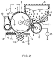
- Fig. 2 is a cross-sectional view of a main section of an electrophotographic device in which magnetic toner of an embodiment of the invention is used.
- Fig. 3 is a cross-sectional view of a main section of an electrophotographic device in which magnetic toner of an embodiment of the invention is used.
- the composition of the toner base particles of a magnetic toner of an embodiment of the invention is shown in Table 1.
- Table 1 Binder resin styrene butyl acrylic copolymer resin (monomer ratio 82/18) 62.5 wt.% melt viscosity at 135°C : 1x10⁵ (poise) melt viscosity at 145°C : 2x10⁴ (poise) Magnetic particles magnetite (BL220 manufactured by Titan Kogyo Kabushiki Gaisha) 35 wt.% * Cr-metal complex azoic dye (S-34 manufactured by Orient Chemical Industries Co.) 1 wt.% ** polypropylene (TP-32 manufactured by Sanyo Chemical Industries, Ltd.) 1.5 wt.% * Charge controlling agent ** Parting agent
- the magnetic toner of the embodiment was manufactured as described below. Materials indicated in Table 1 were mixed by a Henschel mixer (FM-20B manufactured by Mitsui Miike Engineering Co.), then heated and kneaded by a two-shaft type extruder (PCM-30 (manufactured by Ikekai Co.), pulverized roughly to less than 2mm by Rotoplex (manufactured by Alpine AKG.), and pulverized to fine particles by an IDS-2 type jet mill (manufactured by Nippon Neumatic MFG. Co.). The particles were then cut by a DS2-type dispersion separator (manufactured by Nippon Neumatic MFG. Co.). As a result, particles of 8 ⁇ m average particle diameter were provided, and are called toner base particles.
- the magnetic toner of this embodiment is manufactured by mixing in additives with the base particles.
- Table 2 shows additives used in the invention and comparative examples and their characteristics.
- TA-1 is barium titanate fine particles prepared by a hydrothermal composition method
- TA-2 is barium zirconate fine particles manufactured by an oxalate hydrothermal composition method
- TB-1 is lead titanate
- TB-2 is alumina fine particles.
- the barium titanate fine particles were prepared by mixing hydrous titanate and barium hydroxide and reacting them at 200°C in a hydrothermal condition. Then, they were washed, filtered, dried and pulverized. The mol ratio of Ba/Ti is 0.998.
- the blow-off method was applied to measure the chargeable properties of the agents.
- 0.2g of a sample was blown for 180 seconds with 0.2kgf/cm2 air stress, and was then measured.
- roughly crushed magnetic toner base particles were put through a mesh having pores of 100 ⁇ m diameter, and the additives were mixed with the base particles at 10% mixing density.
- the agents mixed with the base particles were put into a 100ml polyethylene bottle, and were agitated for ten minutes at 60rpm.
- the specific surface area is measured by a regular BET measurement method of nitrogen absorption, and a specific surface area measuring apparatus (Flow Sorb2 2300) manufactured by Shimadzu Corporation was used.
- the composition of the magnetic toner of this embodiment is shown in Table 3.
- the diameter of additive is measured by a regular laser diffraction particle sizer, and a measuring apparatus (Coulter LS) manufactured by Coulter electronics, inc. was used. And the toner diameter is measured by an electric resistance method, and a measuring apparatus (Coulter Multisizer) manufactured by Coulter electronics, inc. was also used.
- Table 3 Toner Toner base Inorganic fine particles Hydrophobic silica (*) Toner A1 (Table 1) TA-1 R202(**) 100 wt. parts 1.0 part (***) 1.0 part Toner A2 (Table 1) TA-2 TS-720 (****) 100 wt.
- Table 4 Toner Apparent density Charge amount Toner A1 0.61g/cc -30.0 ⁇ C/g Toner A2 0.50g/cc -32.0 ⁇ C/g Toner B1 0.49g/cc -23.5 ⁇ C/g Toner B2 0.48g/cc -22.2 ⁇ C/g
- the fluidity is indicated as the apparent density.
- a powder tester (PT-E type) manufactured by Hosokawa Micron Co., Ltd. was used for the measurement.
- the charge amount was measured by the blow-off method, and 0.2g of a sample was blown for 180 seconds with 0.2kgf/cm2 air stress and was measured.
- the measurement of charge amount was the same as the measurement applied to the additives, except that a non-coat ferrite carrier was used instead of the magnetic toner base particles.
- toners A1 and A2 have high charge amount and fluidity.
- FIG. 1 is a photoconductor (organic photoconductive drum) which disperses phthalocyanine in a polyester type binder resin; 2 is a magnet which is fixed along the same shaft of photoconductor 1; 3 is a corona charging device which charges the photoconductor negative; 4 is a grid electrode which controls the charge potential of the photoconductor; 5 is signaling light (laser beam); 7 is a magnetic one-component toner; 6 is a toner sump for supplying magnetic toner 7 to the surface of photoconductor 1; 8 is a non-magnetic electrode roller deposited with a gap between itself and photoconductor 1; 9 is a magnet which is deposited inside electrode roller 8 and does not rotate; 10 is an alternating high voltage power source applied to electrode roller 8; and 11 is a scraper made of polyester film for scraping toner on the electrode roller. Residual toner
- a damper 12 makes the flow of toner in the toner sump smooth and prevents toner from being pulverized by its own weight and being stuck between the photoconductor and the electrode roller.
- a corona transfer charging device 13 transfers toner images on the photoconductor to paper.
- Magnetic flux density on the surface of photoconductor 1 is 600Gs. Magnetic force inside the electrode roller is increased so as to improve conveying properties.
- the magnetic pole angle ( ⁇ ) of magnet 2 shown in the figure is 15° .
- the diameter of photoconductor 1 is 30mm, and it rotates at 60mm/s peripheral speed in an arrow direction shown in the figure.
- the diameter of electrode roller 8 is 16mm, and it rotates at 40mm/s peripheral speed in the opposite direction to the rotating direction of the photoconductor (indicated as an arrow in the figure) at a section where the roller and the drum face each other.
- the gap between photoconductor 1 and electrode roller 8 is 300 ⁇ m.
- Photosensitive drum 1 was charged to -500V by corona charging device 3 (applied voltage -4.5kV, and -500V at grid 4). Laser beam 5 was irradiated on photoconductor 1, thus forming electrostatic latent images. The exposure potential of the photoconductor was -90V. In toner sump 6, magnetic toner 7 was adhered to the surface of photoconductor 1 by the magnet. Then, photoconductor 1 was passed in front of electrode roller 8. When photoconductor 1 was passed through an uncharged region, 750VO-p (1.5kV peak to peak) alternating voltage (1kHz in frequency) was applied to electrode roller 8 from alternating current high voltage power source 10.
- Copying tests were directed by applying the electrophotographic method shown in Fig. 1 and using magnetic toner A1 shown in Example 1.
- Image density was measured by a reflection density measuring device (manufactured by Macbeth Co.), and the results were evaluated. According to the results, it was found that images were solid black and even with complete letters and without disordering horizontal lines and scattered toner. The images were high in quality, reproducing 16/mm image lines of 1.4 density. At the same time, images with 1.4 or higher image density were obtained, and there was also no fog in the non-image section.
- FIG. 2 An electrophotographic method of one embodiment is shown in Fig. 2.
- the corona transfer used in the method shown in Fig. 1 is replaced with roller transfer for the transferring step in the method shown in Fig. 2.
- 113 is a transfer roller for transferring toner images on the photoconductor to paper, and is in contact with photoconductor 1.
- the transfer roller is an elastic roller which is composed of a metallic shaft and a conductive elastic member around the shaft.
- the stress of a single transfer roller 113 (about 216mm) against photoconductor 1 is 0-2,000g, preferably 500-1,000g.
- the stress was calculated from the product of displacement and spring factor of a spring used for pressing transfer roller 113 against photoconductor 1.
- the contacting width between the photoconductor and the roller is about 0.5-5mm.
- the rubber hardness of transfer roller 113 is measured by the Asker C measurement method (using not a roller but a block) and is generally less than 80 degrees, more preferably 30-40 degrees.
- Conductive urethane elastomer having 107 ⁇ value of resistance 500V was applied to electrodes provided to the shaft and the surface) including foaming lithium salt was applied around the shaft of 6mm diameter.
- the outside diameter of transfer roller 113 was 16.4mm, and the hardness was 40 degrees, measured by Askar C.
- Transfer roller 113 was in contact with photoconductor 1 by providing stress to the shaft of the roller with a metallic spring. The stress was about 1,000g.
- a chute 14 made of a conductive material introduces transfer paper to transfer roller 113; 15 is a carrier guide which is a conductive member coated with an insulator. Chute 14 and carrier guide 15 are grounded directly or through resistance.
- 16 is transfer paper; 17 is a voltage-generating power source for applying voltage to transfer roller 113; 18 is a cleaning blade for removing residual toner left from the transferring step, and 19 is a cleaning box for holding the residual toner.
- FIG. 3 An electrophotographic method of an embodiment is shown in Fig. 3.
- residual toner recycling is added to the electrophotographic method shown in Fig. 2.
- Residual toner collected in cleaning box 19 is sucked through a transportation pipe inlet 20a, passes through a transportation pipe 20b, and is transported to toner sump 6, so that residual toner left from the transferring step is recycled.
- the method of transporting the residual toner includes a method of using air, a method of transporting the toner in a spiral condition, a method of using magnetic force, a vibrating method, and other known methods. However, the method is not limited. Other characteristics of this example were the same as the characteristics shown in Fig. 2.
- Copying tests were conducted by applying the electrophotographic device shown in Fig. 3 and using magnetic toner A1 of the invention.
- Image density was measured by a reflection density measuring device (manufactured by Macbeth Co.), and the results were evaluated. According to the results, it was found that images were even and solid black with complete letters and without disordering horizontal lines and scattered toner. The images were high in quality, reproducing 16/mm image lines of 1.4 density. At the same time, images with 1.4 or higher image density were obtained, and there was also no fog in the non-image section.
- Example 1 The same composition and process as in Example 1 were conducted so as to prepare magnetic toner B1, except that different additives from the ones in Example 1 were used.
- lead titanate fine particles and hydrophobic silica treated with dimethyl dichlorosilane were used as the additives.
- Image density was measured by a reflection densitometer (manufactured by Macbeth Co.). As a result, it was found that images had low image density and a lot of fog.
- Example 2 The same composition and process as in Example 2 were directed so as to prepare magnetic toner B1, except that different additives from the ones in Example 1 were used.
- hydrophobic silica treated with hexamethylene disilazane and alumina fine powder were used as the addition agents.
- Image density was measured by a reflection densitometer (manufactured by Macbeth Co.). As a result, it was found that images had low image density and a lot of fog.
- the same toner as the one shown in Example 2 was prepared, except that the amount of added magnetic powder was 10% by weight in this example. The toner was heavily scattered and was not good for practical use.
- the same toner as the one shown in Example 2 was prepared, except that the amount of added magnetic powder was 80% by weight in this example.
- the toner had a low charge amount, and images had a lot of fog, so that the toner was not good for practical use.
- the same toner as the one shown in Example 2 was prepared, except that the amount of added silica was 0.05% by weight in this example.
- the toner had poor fluidity, and was not good for practical purpose.
- Example 2 The same toner as the one shown in Example 2 was prepared, except that the amount of added silica was 6 weight parts in this example.
- the silica aggregated intensively, and a lot of white points adhered to a solid black image section, so that the toner was not good for practical use.
- the same toner as the one shown in Example 2 was prepared, except that the amount of added barium titanate fine particles was 0.05 weight parts in this example.
- the same toner as the one shown in Example 2 was prepared, except that the amount of added barium titanate fine particles was 6 weight parts in this example.
Landscapes
- Physics & Mathematics (AREA)
- General Physics & Mathematics (AREA)
- Chemical & Material Sciences (AREA)
- Inorganic Chemistry (AREA)
- Developing Agents For Electrophotography (AREA)
Applications Claiming Priority (12)
| Application Number | Priority Date | Filing Date | Title |
|---|---|---|---|
| JP84529/94 | 1994-04-22 | ||
| JP6084529A JPH07295282A (ja) | 1994-04-22 | 1994-04-22 | 磁性トナー及び電子写真方法 |
| JP6099623A JPH07306543A (ja) | 1994-05-13 | 1994-05-13 | 電子写真方法 |
| JP99623/94 | 1994-05-13 | ||
| JP09962294A JP3734844B2 (ja) | 1994-05-13 | 1994-05-13 | 電子写真方法 |
| JP99622/94 | 1994-05-13 | ||
| JP6103727A JPH07311475A (ja) | 1994-05-18 | 1994-05-18 | 磁性トナー及び電子写真方法 |
| JP103727/94 | 1994-05-18 | ||
| JP6103726A JPH07311474A (ja) | 1994-05-18 | 1994-05-18 | 磁性トナー及び電子写真方法 |
| JP103726/94 | 1994-05-18 | ||
| JP284856/94 | 1994-11-18 | ||
| JP6284856A JPH08146646A (ja) | 1994-11-18 | 1994-11-18 | 磁性トナー及び電子写真方法 |
Publications (1)
| Publication Number | Publication Date |
|---|---|
| EP0681224A1 true EP0681224A1 (fr) | 1995-11-08 |
Family
ID=27551615
Family Applications (1)
| Application Number | Title | Priority Date | Filing Date |
|---|---|---|---|
| EP95105822A Ceased EP0681224A1 (fr) | 1994-04-22 | 1995-04-19 | Révélateur magnétique |
Country Status (2)
| Country | Link |
|---|---|
| US (1) | US5561019A (fr) |
| EP (1) | EP0681224A1 (fr) |
Cited By (4)
| Publication number | Priority date | Publication date | Assignee | Title |
|---|---|---|---|---|
| EP0774696A3 (fr) * | 1995-11-20 | 1997-05-28 | Canon Kabushiki Kaisha | Révélateur pour le développement d'images électrostatiques, procédé de formation d'image et cartouche de traitement |
| EP0784237A3 (fr) * | 1996-01-10 | 1998-01-21 | Canon Kabushiki Kaisha | Révélateur pour le développement d'images électrostatiques, bloc d'assemblage et procédé de formation d'image |
| EP1355198A3 (fr) * | 2002-04-19 | 2005-01-12 | Canon Kabushiki Kaisha | Révélateur, méthode pour former des images l'utilisant, et cartouche de traitement |
| CN107057117A (zh) * | 2016-02-10 | 2017-08-18 | 富士施乐株式会社 | 树脂颗粒组合物 |
Families Citing this family (5)
| Publication number | Priority date | Publication date | Assignee | Title |
|---|---|---|---|---|
| US5702858A (en) * | 1994-04-22 | 1997-12-30 | Matsushita Electric Industrial Co., Ltd. | Toner |
| AU2003268115A1 (en) | 2002-09-09 | 2004-03-29 | Mitsubishi Chemical America, Inc. | Electrostatic toner composition to enhance copy quality by improved fusing and method of manufacturing same |
| US8846288B2 (en) * | 2006-01-30 | 2014-09-30 | Nippon Chemical Industrial Co., Ltd. | External additive for toner and method for producing the same |
| JP4067108B2 (ja) * | 2006-01-30 | 2008-03-26 | 株式会社アイメックス | 静電荷像現像用トナーの製造方法 |
| JP5091685B2 (ja) | 2006-01-30 | 2012-12-05 | 日本化学工業株式会社 | トナー用外添剤およびその製造方法 |
Citations (7)
| Publication number | Priority date | Publication date | Assignee | Title |
|---|---|---|---|---|
| DE3428433A1 (de) * | 1983-08-03 | 1985-02-21 | Canon K.K., Tokio/Tokyo | Entwickler und bilderzeugungsverfahren |
| EP0223594A2 (fr) * | 1985-11-19 | 1987-05-27 | Canon Kabushiki Kaisha | Développateur magnétique sec |
| EP0395026A2 (fr) * | 1989-04-26 | 1990-10-31 | Canon Kabushiki Kaisha | Développateur magnétique, méthode de formation d'image, et appareil de formation d'image |
| EP0427275A2 (fr) * | 1989-11-09 | 1991-05-15 | Canon Kabushiki Kaisha | Toner pour le développement d'images électrostatiques, procédé de formation d'images et appareil de formation d'images |
| EP0488789A1 (fr) * | 1990-11-30 | 1992-06-03 | Mita Industrial Co. Ltd. | Développateur magnétique pour l'électrophotographie |
| EP0541113A1 (fr) * | 1991-11-08 | 1993-05-12 | Canon Kabushiki Kaisha | Révélateur à un composant pour développer des images électrostatiques et méthode de formation d'images |
| EP0581257A1 (fr) * | 1992-07-29 | 1994-02-02 | Matsushita Electric Industrial Co., Ltd. | Toner magnétique pour le développement d'images et procédé pour sa fabrication |
Family Cites Families (9)
| Publication number | Priority date | Publication date | Assignee | Title |
|---|---|---|---|---|
| JPS6032060A (ja) * | 1983-08-03 | 1985-02-19 | Canon Inc | 磁性トナー |
| JPH0727275B2 (ja) * | 1985-04-27 | 1995-03-29 | 京セラ株式会社 | 磁性現像剤およびそれを用いた現像方法 |
| JPH02287459A (ja) * | 1989-04-28 | 1990-11-27 | Canon Inc | 負帯電性現像剤 |
| US5307122A (en) * | 1989-07-28 | 1994-04-26 | Canon Kabushiki Kaisha | Image forming apparatus apparatus unit facsimile apparatus and developer comprising hydrophobic silica fine powder for developing electrostatic images |
| JP2715337B2 (ja) * | 1990-10-26 | 1998-02-18 | キヤノン株式会社 | 画像形成方法 |
| JP2769917B2 (ja) * | 1990-10-26 | 1998-06-25 | キヤノン株式会社 | 磁性現像剤、画像形成方法及び装置ユニット |
| JP3057108B2 (ja) * | 1991-04-25 | 2000-06-26 | コニカ株式会社 | 静電像現像用トナーおよびその製造方法 |
| DE69316513T2 (de) * | 1992-10-15 | 1998-06-04 | Canon Kk | Magnetischer Entwickler für die Entwicklung elektrostatischer Bilder |
| US5370961A (en) * | 1992-12-02 | 1994-12-06 | Eastman Kodak Company | Method of electrostatic transferring very small dry toner particles using an intermediate |
-
1995
- 1995-04-11 US US08/419,988 patent/US5561019A/en not_active Expired - Lifetime
- 1995-04-19 EP EP95105822A patent/EP0681224A1/fr not_active Ceased
Patent Citations (7)
| Publication number | Priority date | Publication date | Assignee | Title |
|---|---|---|---|---|
| DE3428433A1 (de) * | 1983-08-03 | 1985-02-21 | Canon K.K., Tokio/Tokyo | Entwickler und bilderzeugungsverfahren |
| EP0223594A2 (fr) * | 1985-11-19 | 1987-05-27 | Canon Kabushiki Kaisha | Développateur magnétique sec |
| EP0395026A2 (fr) * | 1989-04-26 | 1990-10-31 | Canon Kabushiki Kaisha | Développateur magnétique, méthode de formation d'image, et appareil de formation d'image |
| EP0427275A2 (fr) * | 1989-11-09 | 1991-05-15 | Canon Kabushiki Kaisha | Toner pour le développement d'images électrostatiques, procédé de formation d'images et appareil de formation d'images |
| EP0488789A1 (fr) * | 1990-11-30 | 1992-06-03 | Mita Industrial Co. Ltd. | Développateur magnétique pour l'électrophotographie |
| EP0541113A1 (fr) * | 1991-11-08 | 1993-05-12 | Canon Kabushiki Kaisha | Révélateur à un composant pour développer des images électrostatiques et méthode de formation d'images |
| EP0581257A1 (fr) * | 1992-07-29 | 1994-02-02 | Matsushita Electric Industrial Co., Ltd. | Toner magnétique pour le développement d'images et procédé pour sa fabrication |
Cited By (8)
| Publication number | Priority date | Publication date | Assignee | Title |
|---|---|---|---|---|
| EP0774696A3 (fr) * | 1995-11-20 | 1997-05-28 | Canon Kabushiki Kaisha | Révélateur pour le développement d'images électrostatiques, procédé de formation d'image et cartouche de traitement |
| US5695902A (en) * | 1995-11-20 | 1997-12-09 | Canon Kabushiki Kaisha | Toner for developing electrostatic image, image forming method and process-cartridge |
| EP0784237A3 (fr) * | 1996-01-10 | 1998-01-21 | Canon Kabushiki Kaisha | Révélateur pour le développement d'images électrostatiques, bloc d'assemblage et procédé de formation d'image |
| EP1355198A3 (fr) * | 2002-04-19 | 2005-01-12 | Canon Kabushiki Kaisha | Révélateur, méthode pour former des images l'utilisant, et cartouche de traitement |
| US7141343B2 (en) | 2002-04-19 | 2006-11-28 | Canon Kabushiki Kaisha | Toner, method for forming image using the toner, and process cartridge |
| US7241547B2 (en) | 2002-04-19 | 2007-07-10 | Canon Kabushiki Kaisha | Toner, method for forming image using the toner, and process cartridge |
| CN107057117A (zh) * | 2016-02-10 | 2017-08-18 | 富士施乐株式会社 | 树脂颗粒组合物 |
| CN107057117B (zh) * | 2016-02-10 | 2019-09-17 | 富士施乐株式会社 | 树脂颗粒组合物 |
Also Published As
| Publication number | Publication date |
|---|---|
| US5561019A (en) | 1996-10-01 |
Similar Documents
| Publication | Publication Date | Title |
|---|---|---|
| EP0573933B1 (fr) | Procédé de formation d'image | |
| US5534982A (en) | Developing apparatus | |
| US5702858A (en) | Toner | |
| US5561019A (en) | Magnetic toner | |
| JP3132711B2 (ja) | 静電荷現像用トナー組成物および画像形成方法 | |
| US6057073A (en) | Toner for developing electrostatic image, image forming method, developing apparatus unit, and process cartridge | |
| JPH07271090A (ja) | 磁性トナーとその製造方法及び電子写真方法 | |
| JP3412319B2 (ja) | トナー | |
| JPH06317933A (ja) | 磁性トナー及び電子写真方法 | |
| JP3734844B2 (ja) | 電子写真方法 | |
| JPH07295282A (ja) | 磁性トナー及び電子写真方法 | |
| EP0581257B1 (fr) | Toner magnétique électrophotographique pour le développement d'images et procédé pour sa fabrication | |
| JP3697028B2 (ja) | 画像形成装置 | |
| JPH0862887A (ja) | 静電荷像現像用トナー及び画像形成方法 | |
| JP2563737B2 (ja) | 磁性トナー及び電子写真方法 | |
| JPH07306543A (ja) | 電子写真方法 | |
| JP2002214887A (ja) | 画像形成装置及び当該装置用の磁性現像剤 | |
| JPH05142857A (ja) | 静電潜像現像用トナーおよびそれを用いた静電潜像現像方法 | |
| JPH07311474A (ja) | 磁性トナー及び電子写真方法 | |
| JPH07181724A (ja) | 磁性トナー及び電子写真方法 | |
| JPH08240937A (ja) | 正帯電トナー及び電子写真方法 | |
| JPH07120970A (ja) | 磁性トナーおよび電子写真方法 | |
| JPH08146646A (ja) | 磁性トナー及び電子写真方法 | |
| JPH06123998A (ja) | 磁性トナー及び電子写真方法 | |
| JPH07311475A (ja) | 磁性トナー及び電子写真方法 |
Legal Events
| Date | Code | Title | Description |
|---|---|---|---|
| PUAI | Public reference made under article 153(3) epc to a published international application that has entered the european phase |
Free format text: ORIGINAL CODE: 0009012 |
|
| AK | Designated contracting states |
Kind code of ref document: A1 Designated state(s): DE GB |
|
| 17P | Request for examination filed |
Effective date: 19951013 |
|
| 17Q | First examination report despatched |
Effective date: 19960222 |
|
| GRAG | Despatch of communication of intention to grant |
Free format text: ORIGINAL CODE: EPIDOS AGRA |
|
| STAA | Information on the status of an ep patent application or granted ep patent |
Free format text: STATUS: THE APPLICATION HAS BEEN REFUSED |
|
| 18R | Application refused |
Effective date: 20020315 |