EP0681228A1 - Kopplungsvorrichtung zwischen einer mechanischen Energiequelle and einem elektrischen Generator in einer Zeitmessvorrichtung - Google Patents
Kopplungsvorrichtung zwischen einer mechanischen Energiequelle and einem elektrischen Generator in einer Zeitmessvorrichtung Download PDFInfo
- Publication number
- EP0681228A1 EP0681228A1 EP95106408A EP95106408A EP0681228A1 EP 0681228 A1 EP0681228 A1 EP 0681228A1 EP 95106408 A EP95106408 A EP 95106408A EP 95106408 A EP95106408 A EP 95106408A EP 0681228 A1 EP0681228 A1 EP 0681228A1
- Authority
- EP
- European Patent Office
- Prior art keywords
- turns
- spring
- tube
- cylindrical element
- shaft
- Prior art date
- Legal status (The legal status is an assumption and is not a legal conclusion. Google has not performed a legal analysis and makes no representation as to the accuracy of the status listed.)
- Granted
Links
Images

Classifications
-
- G—PHYSICS
- G04—HOROLOGY
- G04C—ELECTROMECHANICAL CLOCKS OR WATCHES
- G04C10/00—Arrangements of electric power supplies in time-pieces
Definitions
- the present invention relates to a coupling device between a mechanical energy source and an electrical energy generator in a timepiece comprising a shaft driven by said mechanical energy source and a cylindrical element fixedly and coaxially mounted on this tree.
- Such a coupling device is known from US Pat. No. 4,644,246 for supplying current, in particular a timepiece.
- the latter comprises an AC generator, a rechargeable battery and a charging system interposed between the generator and the battery, the generator comprising a multipolar rotor carrying permanent magnets and a stator provided with windings delivering the AC current.
- An eccentric mass drives the rotor.
- the rotor, stator and ground are mounted coaxially.
- the coupling between the mass, source of mechanical energy, and the rotor of the electric power generator is carried out, at least in one described embodiment, by a spiral spring one end of which is attached to a cylindrical element making part of the pivot shaft of the eccentric mass, the other end of which is attached to a cage carrying the generator rotor.
- the rotor In the idle state, the rotor is magnetically retained by the stator, which constitutes a certain positioning torque.
- the mass tends or winds the spiral spring around the cylindrical element until the energy accumulated by the spring exceeds the positioning energy of the rotor relative to the stator. From this moment, the rotor is released and rotated at high speed until the kinetic energy stored by the spring, the generator then producing a high electromotive force to charge the battery.
- the present invention is characterized in that said cylindrical element is surmounted by a tube mounted to rotate freely around said shaft and arranged to drive said generator, a helical spring being adjusted with fatty friction on the cylindrical element and on the tube by its first and last turns respectively, a space being provided between said tube and cylindrical element and the central turns of said spring.
- the coupling device 1 fits between a source of mechanical energy 2 and a generator of electrical energy 3 as seen in FIG. 1.
- the source of mechanical energy 2 is an eccentric oscillating weight of the type found on mechanical self-winding watches.
- the electric power generator 3 is made up of a magnetic rotor 33 carried by a shaft 27. By turning, the rotor produces variations in magnetic flux on a winding 34 disposed in a casing 40 for flux return.
- the casing is fixed in a plate 32 of the watch.
- the AC alternating current collected at the terminals of the coil 34 is intended to charge an accumulator of the gold cap type for example, and this via a conventional rectifier. In turn the accumulator will power a quartz oscillator, a frequency divider and a stepping motor as is well known in electronic watches.
- the oscillating weight is driven by a bidirectional movement which must be made unidirectional to wind a barrel spring.
- this oscillating mass pivots in the center of the movement and coaxially with the switch and is supported by a ball bearing, a part 41 of which is represented in FIG. 1.
- To this mass is linked a wheel 30 whose teeth are engaged with a first pawl wheel 13.
- the wheel 30 also meshes on a second pawl wheel 14 as shown in dotted lines in FIG. 2.
- the first pawl wheel 13 (see FIGS. 1 and 2) cooperates with a first driving disc 50 driven out a shaft 4 driving the coupling device 1 according to the invention.
- the second pawl wheel 14 (see dotted representation of FIG.
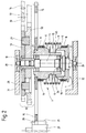
- FIG. 2 shows that on the shaft 4 driven as we saw above, is mounted fixedly and coaxially, by driving for example , a cylindrical element 5.
- the cylindrical element 5 is surmounted by a tube 6 arranged to rotate freely around the shaft 4.
- the freedom of the tube 6 is ensured by two stones 23 and 24 driven into the tube and whose hole center is freely adjusted on the shaft 4 which is arranged to drive the generator 3 ( Figure 1).
- a helical spring 7 is adjusted with fatty friction on the cylindrical element 5 and on the tube 6 by its first 8 and last 9 turns respectively.
- FIG. 2 also shows that a space 10 is provided between the tube and cylindrical element and the central turns 11 that the spring 7 presents.
- the generator 3 is driven by a wheel 15 of large diameter.
- This wheel is integral with the tube 6.
- the teeth 26 of this wheel 15 are engaged with a pinion 25 carried by the shaft 27 of the generator 3.
- the shaft 4 of the coupling device pivots between stage 32 of the movement and a bridge 31 carried by this movement.
- the operation of the coupling device is as follows:
- the shaft 4 When the shaft 4 rotates (unidirectionally as mentioned above), it drives the first turns 8 of the spring 7, tightened with fatty friction around the cylindrical element 5 and wound in a direction which tends to tighten this friction even more , to shoot with him.
- the last turns 9 of the spring 7 wound with fatty friction on this tube are further tightened around it, which has the consequence of tensioning the spring 7 in its central turns 11 which contract and decrease in diameter to thus accumulate the energy developed by the source of mechanical energy from the oscillating mass.
- the torque stored by the spring 7 exceeds the positioning torque of the generator 3, the latter starts to rotate at high speed, driven as it is by the wheel 15 secured to the tube 6.
- the generator will rotate until exhaust the potential energy stored in the spring 7, then will continue its race for a few more laps because, as of this exhaustion, the spring 7 tends to slip at the place of the first and last turns 8 and 9, which allows the generator 3 further releasing the kinetic energy acquired by its rotor 33.
- This device shows that not only is it free of shocks (the spring 7 is not fixed anywhere) thereby giving it a long service life, but also that it is capable of restoring the energy which has was conferred almost entirely, since yields of the order of 98% could be measured. It is in fact a very advantageous device allowing on the one hand the clutch and the disengagement between a source of mechanical energy and a generator of electrical energy and on the other hand the almost total restitution of energy stored by the mechanical energy source.
- the proposed device also makes it possible to transform the relatively slow speed of the mechanical energy source (approximately 240 revolutions / minute) into a very rapid speed (approximately 15,000 revolutions / minute) which is favorable to the overall efficiency of the generator.
- the strong multiplication of speed generated by the ratio between the number of teeth of the pinion 25 of the generator shaft and the number of teeth 26 of the big wheel uniting with the device of the invention contributes significantly important at this high speed.
- the generator is always driven at the same speed, since it is released only when its positioning torque is less than the mechanical torque stored by the spring. This has the advantage of ensuring a constant output, the generator always restoring the same amount of energy.
- the helical spring has central turns 11 whose diameter is larger than the diameter of the first and last turns 8 and 9, these first and last turns having a substantially equal diameter. Therefore the outer diameter 16 of the tube 6 and the outer diameter 18 of the cylindrical member 5 are also substantially the same. This way we simplify the way of making the spring 7.
- the tube 6 is stepped according to at least two different diameters, the first 16 receiving the last turns 9 of the spring 7 and the second 17, smaller penetrating at least partially inside the cylindrical element 5 shaped into a cup, the outside diameter 18 of said cup receiving the first turns 8 of the spring 7.
- a spring 7 of constant diameter from top to bottom since a space 10 would be always formed between the lower part 45 of the tube 6 and the central turns 11 of the spring 7.
Landscapes
- Engineering & Computer Science (AREA)
- Power Engineering (AREA)
- Physics & Mathematics (AREA)
- General Physics & Mathematics (AREA)
- Electromechanical Clocks (AREA)
- Connection Of Motors, Electrical Generators, Mechanical Devices, And The Like (AREA)
Applications Claiming Priority (2)
| Application Number | Priority Date | Filing Date | Title |
|---|---|---|---|
| CH1398/94 | 1994-05-04 | ||
| CH01398/94A CH686474B5 (fr) | 1994-05-04 | 1994-05-04 | Dispositif de couplage entre une source d'énergie mécanique et une génératrice électrique dans une pièce d'horlogerie. |
Publications (2)
| Publication Number | Publication Date |
|---|---|
| EP0681228A1 true EP0681228A1 (de) | 1995-11-08 |
| EP0681228B1 EP0681228B1 (de) | 1998-07-08 |
Family
ID=4209498
Family Applications (1)
| Application Number | Title | Priority Date | Filing Date |
|---|---|---|---|
| EP95106408A Expired - Lifetime EP0681228B1 (de) | 1994-05-04 | 1995-04-28 | Kopplungsvorrichtung zwischen einer mechanischen Energiequelle and einem elektrischen Generator in einer Zeitmessvorrichtung |
Country Status (8)
| Country | Link |
|---|---|
| US (1) | US5532982A (de) |
| EP (1) | EP0681228B1 (de) |
| JP (1) | JP3607359B2 (de) |
| KR (1) | KR100321491B1 (de) |
| CN (1) | CN1088859C (de) |
| CH (1) | CH686474B5 (de) |
| DE (1) | DE69503313T2 (de) |
| TW (1) | TW285724B (de) |
Cited By (5)
| Publication number | Priority date | Publication date | Assignee | Title |
|---|---|---|---|---|
| EP0791867A4 (de) * | 1995-09-13 | 1997-12-10 | Citizen Watch Co Ltd | Kleiner elektronischer apparat mit generator |
| EP1213626A1 (de) * | 2000-12-07 | 2002-06-12 | Eta SA Fabriques d'Ebauches | Stossfeste Übertragungsmittel zum Antrieb eines Generators durch eine Schwungmasse, insbesondere in einer Uhr |
| NL1017551C2 (nl) * | 2001-03-09 | 2002-09-10 | Kinetron Bv | Elektrisch voedingsspanningssysteem voor het omzetten van kinetische energie in elektrische energie ten behoeve van miniatuurinrichtingen. |
| DE102011106785A1 (de) | 2011-07-06 | 2013-01-10 | JuB-Creative Product GmbH | Kinetischer Wandler |
| WO2023105270A1 (fr) * | 2021-12-09 | 2023-06-15 | Mb & F Sa | Mouvements horlogers à chronographe et leur application dans des pièces d'horlogerie |
Families Citing this family (3)
| Publication number | Priority date | Publication date | Assignee | Title |
|---|---|---|---|---|
| EP0905587B1 (de) * | 1997-09-26 | 2002-11-13 | Seiko Epson Corporation | Elektrisch geregelte mechanische Uhr |
| US6288519B1 (en) | 1998-12-22 | 2001-09-11 | Ericsson Inc. | Charging and vibrating method using movable magnets for a product using rechargeable batteries |
| EP1085383B1 (de) * | 1999-09-17 | 2009-01-21 | ETA SA Manufacture Horlogère Suisse | Stossfeste Vorrichtung für einen durch eine Schwungmasse angetriebenen Generator |
Citations (3)
| Publication number | Priority date | Publication date | Assignee | Title |
|---|---|---|---|---|
| EP0170303A1 (de) * | 1984-07-03 | 1986-02-05 | Kinetron B.V. | Elektrisches Energieversorgungssystem für tragbare miniaturisierte Energieverbrauchsvorrichtungen |
| JPS63128286A (ja) * | 1986-11-19 | 1988-05-31 | Seiko Epson Corp | 発電装置付電子腕時計 |
| WO1992004662A1 (en) * | 1990-09-07 | 1992-03-19 | Kinetron B.V. | Generator |
Family Cites Families (4)
| Publication number | Priority date | Publication date | Assignee | Title |
|---|---|---|---|---|
| KR950001429Y1 (ko) * | 1988-01-25 | 1995-03-06 | 세이꼬 엡슨 가부시끼가이샤 | 발전장치 부착 전자 팔목시계 |
| CH671669B5 (de) * | 1988-03-21 | 1990-03-30 | Phare Jean D Eve Sa Le | |
| CH680252B5 (de) * | 1990-08-21 | 1993-01-29 | Ebauchesfabrik Eta Ag | |
| DE59107118D1 (de) * | 1990-10-22 | 1996-02-01 | Gigandet Charles Sa | Armbanduhr |
-
1994
- 1994-05-04 CH CH01398/94A patent/CH686474B5/fr not_active IP Right Cessation
-
1995
- 1995-04-20 TW TW084103917A patent/TW285724B/zh active
- 1995-04-25 KR KR1019950009688A patent/KR100321491B1/ko not_active Expired - Fee Related
- 1995-04-27 US US08/429,574 patent/US5532982A/en not_active Expired - Lifetime
- 1995-04-28 DE DE69503313T patent/DE69503313T2/de not_active Expired - Lifetime
- 1995-04-28 EP EP95106408A patent/EP0681228B1/de not_active Expired - Lifetime
- 1995-05-01 JP JP12884095A patent/JP3607359B2/ja not_active Expired - Fee Related
- 1995-05-03 CN CN95105759A patent/CN1088859C/zh not_active Expired - Lifetime
Patent Citations (3)
| Publication number | Priority date | Publication date | Assignee | Title |
|---|---|---|---|---|
| EP0170303A1 (de) * | 1984-07-03 | 1986-02-05 | Kinetron B.V. | Elektrisches Energieversorgungssystem für tragbare miniaturisierte Energieverbrauchsvorrichtungen |
| JPS63128286A (ja) * | 1986-11-19 | 1988-05-31 | Seiko Epson Corp | 発電装置付電子腕時計 |
| WO1992004662A1 (en) * | 1990-09-07 | 1992-03-19 | Kinetron B.V. | Generator |
Non-Patent Citations (2)
| Title |
|---|
| A.G. RANDALL: "Technical Report - The Jean d'Eve Samara", HOROLOGICAL JOURNAL, vol. 132, no. 4, UPTON GB, pages 124 - 125, XP000054948 * |
| PATENT ABSTRACTS OF JAPAN vol. 12, no. 383 (P - 770) 13 October 1988 (1988-10-13) * |
Cited By (9)
| Publication number | Priority date | Publication date | Assignee | Title |
|---|---|---|---|---|
| EP0791867A4 (de) * | 1995-09-13 | 1997-12-10 | Citizen Watch Co Ltd | Kleiner elektronischer apparat mit generator |
| US5903071A (en) * | 1995-09-13 | 1999-05-11 | Citizen Watch Co., Ltd. | Small electric apparatus equipped with generator |
| EP1213626A1 (de) * | 2000-12-07 | 2002-06-12 | Eta SA Fabriques d'Ebauches | Stossfeste Übertragungsmittel zum Antrieb eines Generators durch eine Schwungmasse, insbesondere in einer Uhr |
| US6587401B2 (en) | 2000-12-07 | 2003-07-01 | Eta Sa Fabriques D'ebauches | Anti-shock transmission device for driving a generator by an oscillating weight in particular in a watch |
| NL1017551C2 (nl) * | 2001-03-09 | 2002-09-10 | Kinetron Bv | Elektrisch voedingsspanningssysteem voor het omzetten van kinetische energie in elektrische energie ten behoeve van miniatuurinrichtingen. |
| EP1239349A1 (de) * | 2001-03-09 | 2002-09-11 | Kinetron B.V. | In Miniatur-Geräten verwendbare Stromversorgungsvorrichtung zur Umformung von kinetischer Energie in elektrische Energie |
| DE102011106785A1 (de) | 2011-07-06 | 2013-01-10 | JuB-Creative Product GmbH | Kinetischer Wandler |
| DE102011106785B4 (de) * | 2011-07-06 | 2015-07-23 | JuB-Creative Product GmbH | Kinetischer Wandler |
| WO2023105270A1 (fr) * | 2021-12-09 | 2023-06-15 | Mb & F Sa | Mouvements horlogers à chronographe et leur application dans des pièces d'horlogerie |
Also Published As
| Publication number | Publication date |
|---|---|
| JP3607359B2 (ja) | 2005-01-05 |
| KR950033740A (ko) | 1995-12-26 |
| KR100321491B1 (ko) | 2002-07-02 |
| CN1113018A (zh) | 1995-12-06 |
| JPH08152487A (ja) | 1996-06-11 |
| TW285724B (de) | 1996-09-11 |
| CN1088859C (zh) | 2002-08-07 |
| HK1012445A1 (en) | 1999-07-30 |
| EP0681228B1 (de) | 1998-07-08 |
| CH686474GA3 (fr) | 1996-04-15 |
| DE69503313T2 (de) | 1999-03-11 |
| CH686474B5 (fr) | 1996-10-15 |
| US5532982A (en) | 1996-07-02 |
| DE69503313D1 (de) | 1998-08-13 |
Similar Documents
| Publication | Publication Date | Title |
|---|---|---|
| EP1085383B1 (de) | Stossfeste Vorrichtung für einen durch eine Schwungmasse angetriebenen Generator | |
| EP2044490B1 (de) | Elektromechanische hemmungseinrichtung und diese einrichtung benutzender uhrenteil | |
| EP1266268B1 (de) | Aufzugvorrichtung für uhren | |
| EP1521142B1 (de) | Uhr mit einem mechanischen Uhrwerk, das mit einem elektronischen Regulator gekoppelt ist | |
| WO1989006833A1 (fr) | Montre electronique pourvue d'un generateur de courant | |
| EP3299908B1 (de) | Armbanduhr mit automatischem aufzug | |
| EP0681228B1 (de) | Kopplungsvorrichtung zwischen einer mechanischen Energiequelle and einem elektrischen Generator in einer Zeitmessvorrichtung | |
| EP1099990A1 (de) | Generator für Zeitmessgerät | |
| WO1999049556A1 (fr) | Convertisseur d'energie mecanique en energie electrique et appareil electronique muni d'un tel convertisseur | |
| EP3944027B1 (de) | Tragbares gerät, insbesondere armbanduhr, das mit einer stromquellevorrichtung mit einem elektromechanischen wandler ausgestattet ist | |
| EP1544692B1 (de) | Elektromechanische Uhr, die mit einer Gangreserveanzeige ausgerüstet ist | |
| EP2391926B1 (de) | Uhrwerk | |
| EP4092492B1 (de) | Uhrwerk, das einen generator umfasst | |
| CH692875A5 (fr) | Dispositif d'entraînement d'un générateur et instrument de petit volume muni d'un tel dispositif. | |
| CH637464A5 (en) | Solar power collector | |
| EP3065003B1 (de) | Uhrwerk | |
| CH692874A5 (fr) | Instrument de petit volume muni d'un dispositif de limitation de la puissance mécanique fournie par une masse oscillante. | |
| EP2053474B1 (de) | Chronographenuhr | |
| EP1109082A1 (de) | Generator insbesondere für Uhrwerk | |
| CH710521A2 (fr) | Dispositif de génération d'électricité sur demande pour pièces d'horlogerie. | |
| EP4443246B1 (de) | Geschwindigkeitsregelvorrichtung für einen drehteil einer uhr | |
| CH712957A2 (fr) | Montre à remontage automatique. | |
| EP0918265B1 (de) | Generatorantriebsvorrichtung für kleine Instrumente | |
| CH717674A2 (fr) | Objet portable, notamment montre bracelet, comprenant un dispositif d'alimentation muni d'un convertisseur électromécanique. | |
| HK1012445B (en) | Means for coupling a mechanical energy source with an electric generator in a time piece |
Legal Events
| Date | Code | Title | Description |
|---|---|---|---|
| PUAI | Public reference made under article 153(3) epc to a published international application that has entered the european phase |
Free format text: ORIGINAL CODE: 0009012 |
|
| AK | Designated contracting states |
Kind code of ref document: A1 Designated state(s): DE FR GB NL |
|
| 17P | Request for examination filed |
Effective date: 19960131 |
|
| GRAG | Despatch of communication of intention to grant |
Free format text: ORIGINAL CODE: EPIDOS AGRA |
|
| 17Q | First examination report despatched |
Effective date: 19970731 |
|
| GRAG | Despatch of communication of intention to grant |
Free format text: ORIGINAL CODE: EPIDOS AGRA |
|
| GRAH | Despatch of communication of intention to grant a patent |
Free format text: ORIGINAL CODE: EPIDOS IGRA |
|
| GRAH | Despatch of communication of intention to grant a patent |
Free format text: ORIGINAL CODE: EPIDOS IGRA |
|
| GRAA | (expected) grant |
Free format text: ORIGINAL CODE: 0009210 |
|
| AK | Designated contracting states |
Kind code of ref document: B1 Designated state(s): DE FR GB NL |
|
| REF | Corresponds to: |
Ref document number: 69503313 Country of ref document: DE Date of ref document: 19980813 |
|
| GBT | Gb: translation of ep patent filed (gb section 77(6)(a)/1977) |
Effective date: 19980928 |
|
| PLBE | No opposition filed within time limit |
Free format text: ORIGINAL CODE: 0009261 |
|
| STAA | Information on the status of an ep patent application or granted ep patent |
Free format text: STATUS: NO OPPOSITION FILED WITHIN TIME LIMIT |
|
| 26N | No opposition filed | ||
| REG | Reference to a national code |
Ref country code: GB Ref legal event code: IF02 |
|
| PGFP | Annual fee paid to national office [announced via postgrant information from national office to epo] |
Ref country code: NL Payment date: 20040325 Year of fee payment: 10 |
|
| PGFP | Annual fee paid to national office [announced via postgrant information from national office to epo] |
Ref country code: GB Payment date: 20040329 Year of fee payment: 10 |
|
| PG25 | Lapsed in a contracting state [announced via postgrant information from national office to epo] |
Ref country code: GB Free format text: LAPSE BECAUSE OF NON-PAYMENT OF DUE FEES Effective date: 20050428 |
|
| PG25 | Lapsed in a contracting state [announced via postgrant information from national office to epo] |
Ref country code: NL Free format text: LAPSE BECAUSE OF NON-PAYMENT OF DUE FEES Effective date: 20051101 |
|
| GBPC | Gb: european patent ceased through non-payment of renewal fee |
Effective date: 20050428 |
|
| NLV4 | Nl: lapsed or anulled due to non-payment of the annual fee |
Effective date: 20051101 |
|
| PGFP | Annual fee paid to national office [announced via postgrant information from national office to epo] |
Ref country code: FR Payment date: 20140422 Year of fee payment: 20 Ref country code: DE Payment date: 20140321 Year of fee payment: 20 |
|
| REG | Reference to a national code |
Ref country code: DE Ref legal event code: R071 Ref document number: 69503313 Country of ref document: DE |