EP0682174A2 - Dieselpartikelfilter und Steuereinrichtung dafür - Google Patents
Dieselpartikelfilter und Steuereinrichtung dafür Download PDFInfo
- Publication number
- EP0682174A2 EP0682174A2 EP95303219A EP95303219A EP0682174A2 EP 0682174 A2 EP0682174 A2 EP 0682174A2 EP 95303219 A EP95303219 A EP 95303219A EP 95303219 A EP95303219 A EP 95303219A EP 0682174 A2 EP0682174 A2 EP 0682174A2
- Authority
- EP
- European Patent Office
- Prior art keywords
- filter
- main filter
- wire net
- main
- sub
- Prior art date
- Legal status (The legal status is an assumption and is not a legal conclusion. Google has not performed a legal analysis and makes no representation as to the accuracy of the status listed.)
- Granted
Links
Images



Classifications
-
- F—MECHANICAL ENGINEERING; LIGHTING; HEATING; WEAPONS; BLASTING
- F01—MACHINES OR ENGINES IN GENERAL; ENGINE PLANTS IN GENERAL; STEAM ENGINES
- F01N—GAS-FLOW SILENCERS OR EXHAUST APPARATUS FOR MACHINES OR ENGINES IN GENERAL; GAS-FLOW SILENCERS OR EXHAUST APPARATUS FOR INTERNAL-COMBUSTION ENGINES
- F01N3/00—Exhaust or silencing apparatus having means for purifying, rendering innocuous, or otherwise treating exhaust
- F01N3/02—Exhaust or silencing apparatus having means for purifying, rendering innocuous, or otherwise treating exhaust for cooling, or for removing solid constituents of, exhaust
- F01N3/021—Exhaust or silencing apparatus having means for purifying, rendering innocuous, or otherwise treating exhaust for cooling, or for removing solid constituents of, exhaust by means of filters
- F01N3/022—Exhaust or silencing apparatus having means for purifying, rendering innocuous, or otherwise treating exhaust for cooling, or for removing solid constituents of, exhaust by means of filters characterised by specially adapted filtering structure, e.g. honeycomb, mesh or fibrous
- F01N3/0226—Exhaust or silencing apparatus having means for purifying, rendering innocuous, or otherwise treating exhaust for cooling, or for removing solid constituents of, exhaust by means of filters characterised by specially adapted filtering structure, e.g. honeycomb, mesh or fibrous the structure being fibrous
-
- F—MECHANICAL ENGINEERING; LIGHTING; HEATING; WEAPONS; BLASTING
- F01—MACHINES OR ENGINES IN GENERAL; ENGINE PLANTS IN GENERAL; STEAM ENGINES
- F01N—GAS-FLOW SILENCERS OR EXHAUST APPARATUS FOR MACHINES OR ENGINES IN GENERAL; GAS-FLOW SILENCERS OR EXHAUST APPARATUS FOR INTERNAL-COMBUSTION ENGINES
- F01N3/00—Exhaust or silencing apparatus having means for purifying, rendering innocuous, or otherwise treating exhaust
- F01N3/02—Exhaust or silencing apparatus having means for purifying, rendering innocuous, or otherwise treating exhaust for cooling, or for removing solid constituents of, exhaust
- F01N3/021—Exhaust or silencing apparatus having means for purifying, rendering innocuous, or otherwise treating exhaust for cooling, or for removing solid constituents of, exhaust by means of filters
- F01N3/022—Exhaust or silencing apparatus having means for purifying, rendering innocuous, or otherwise treating exhaust for cooling, or for removing solid constituents of, exhaust by means of filters characterised by specially adapted filtering structure, e.g. honeycomb, mesh or fibrous
-
- F—MECHANICAL ENGINEERING; LIGHTING; HEATING; WEAPONS; BLASTING
- F01—MACHINES OR ENGINES IN GENERAL; ENGINE PLANTS IN GENERAL; STEAM ENGINES
- F01N—GAS-FLOW SILENCERS OR EXHAUST APPARATUS FOR MACHINES OR ENGINES IN GENERAL; GAS-FLOW SILENCERS OR EXHAUST APPARATUS FOR INTERNAL-COMBUSTION ENGINES
- F01N3/00—Exhaust or silencing apparatus having means for purifying, rendering innocuous, or otherwise treating exhaust
- F01N3/02—Exhaust or silencing apparatus having means for purifying, rendering innocuous, or otherwise treating exhaust for cooling, or for removing solid constituents of, exhaust
- F01N3/021—Exhaust or silencing apparatus having means for purifying, rendering innocuous, or otherwise treating exhaust for cooling, or for removing solid constituents of, exhaust by means of filters
- F01N3/023—Exhaust or silencing apparatus having means for purifying, rendering innocuous, or otherwise treating exhaust for cooling, or for removing solid constituents of, exhaust by means of filters using means for regenerating the filters, e.g. by burning trapped particles
- F01N3/027—Exhaust or silencing apparatus having means for purifying, rendering innocuous, or otherwise treating exhaust for cooling, or for removing solid constituents of, exhaust by means of filters using means for regenerating the filters, e.g. by burning trapped particles using electric or magnetic heating means
-
- F—MECHANICAL ENGINEERING; LIGHTING; HEATING; WEAPONS; BLASTING
- F01—MACHINES OR ENGINES IN GENERAL; ENGINE PLANTS IN GENERAL; STEAM ENGINES
- F01N—GAS-FLOW SILENCERS OR EXHAUST APPARATUS FOR MACHINES OR ENGINES IN GENERAL; GAS-FLOW SILENCERS OR EXHAUST APPARATUS FOR INTERNAL-COMBUSTION ENGINES
- F01N3/00—Exhaust or silencing apparatus having means for purifying, rendering innocuous, or otherwise treating exhaust
- F01N3/02—Exhaust or silencing apparatus having means for purifying, rendering innocuous, or otherwise treating exhaust for cooling, or for removing solid constituents of, exhaust
- F01N3/021—Exhaust or silencing apparatus having means for purifying, rendering innocuous, or otherwise treating exhaust for cooling, or for removing solid constituents of, exhaust by means of filters
- F01N3/031—Exhaust or silencing apparatus having means for purifying, rendering innocuous, or otherwise treating exhaust for cooling, or for removing solid constituents of, exhaust by means of filters having means for by-passing filters, e.g. when clogged or during cold engine start
- F01N3/032—Exhaust or silencing apparatus having means for purifying, rendering innocuous, or otherwise treating exhaust for cooling, or for removing solid constituents of, exhaust by means of filters having means for by-passing filters, e.g. when clogged or during cold engine start during filter regeneration only
-
- F—MECHANICAL ENGINEERING; LIGHTING; HEATING; WEAPONS; BLASTING
- F01—MACHINES OR ENGINES IN GENERAL; ENGINE PLANTS IN GENERAL; STEAM ENGINES
- F01N—GAS-FLOW SILENCERS OR EXHAUST APPARATUS FOR MACHINES OR ENGINES IN GENERAL; GAS-FLOW SILENCERS OR EXHAUST APPARATUS FOR INTERNAL-COMBUSTION ENGINES
- F01N9/00—Electrical control of exhaust gas treating apparatus
- F01N9/002—Electrical control of exhaust gas treating apparatus of filter regeneration
-
- F—MECHANICAL ENGINEERING; LIGHTING; HEATING; WEAPONS; BLASTING
- F01—MACHINES OR ENGINES IN GENERAL; ENGINE PLANTS IN GENERAL; STEAM ENGINES
- F01N—GAS-FLOW SILENCERS OR EXHAUST APPARATUS FOR MACHINES OR ENGINES IN GENERAL; GAS-FLOW SILENCERS OR EXHAUST APPARATUS FOR INTERNAL-COMBUSTION ENGINES
- F01N13/00—Exhaust or silencing apparatus characterised by constructional features
-
- F—MECHANICAL ENGINEERING; LIGHTING; HEATING; WEAPONS; BLASTING
- F01—MACHINES OR ENGINES IN GENERAL; ENGINE PLANTS IN GENERAL; STEAM ENGINES
- F01N—GAS-FLOW SILENCERS OR EXHAUST APPARATUS FOR MACHINES OR ENGINES IN GENERAL; GAS-FLOW SILENCERS OR EXHAUST APPARATUS FOR INTERNAL-COMBUSTION ENGINES
- F01N2240/00—Combination or association of two or more different exhaust treating devices, or of at least one such device with an auxiliary device, not covered by indexing codes F01N2230/00 or F01N2250/00, one of the devices being
- F01N2240/36—Combination or association of two or more different exhaust treating devices, or of at least one such device with an auxiliary device, not covered by indexing codes F01N2230/00 or F01N2250/00, one of the devices being an exhaust flap
-
- F—MECHANICAL ENGINEERING; LIGHTING; HEATING; WEAPONS; BLASTING
- F02—COMBUSTION ENGINES; HOT-GAS OR COMBUSTION-PRODUCT ENGINE PLANTS
- F02B—INTERNAL-COMBUSTION PISTON ENGINES; COMBUSTION ENGINES IN GENERAL
- F02B3/00—Engines characterised by air compression and subsequent fuel addition
- F02B3/06—Engines characterised by air compression and subsequent fuel addition with compression ignition
-
- Y—GENERAL TAGGING OF NEW TECHNOLOGICAL DEVELOPMENTS; GENERAL TAGGING OF CROSS-SECTIONAL TECHNOLOGIES SPANNING OVER SEVERAL SECTIONS OF THE IPC; TECHNICAL SUBJECTS COVERED BY FORMER USPC CROSS-REFERENCE ART COLLECTIONS [XRACs] AND DIGESTS
- Y02—TECHNOLOGIES OR APPLICATIONS FOR MITIGATION OR ADAPTATION AGAINST CLIMATE CHANGE
- Y02T—CLIMATE CHANGE MITIGATION TECHNOLOGIES RELATED TO TRANSPORTATION
- Y02T10/00—Road transport of goods or passengers
- Y02T10/10—Internal combustion engine [ICE] based vehicles
- Y02T10/40—Engine management systems
-
- Y—GENERAL TAGGING OF NEW TECHNOLOGICAL DEVELOPMENTS; GENERAL TAGGING OF CROSS-SECTIONAL TECHNOLOGIES SPANNING OVER SEVERAL SECTIONS OF THE IPC; TECHNICAL SUBJECTS COVERED BY FORMER USPC CROSS-REFERENCE ART COLLECTIONS [XRACs] AND DIGESTS
- Y10—TECHNICAL SUBJECTS COVERED BY FORMER USPC
- Y10S—TECHNICAL SUBJECTS COVERED BY FORMER USPC CROSS-REFERENCE ART COLLECTIONS [XRACs] AND DIGESTS
- Y10S55/00—Gas separation
- Y10S55/30—Exhaust treatment
Definitions
- the present invention relates to a diesel particulate filter for collecting and burning particulates in exhaust gases of a diesel engine and a control device therefor.
- the diesel engine employs a heterogeneous combustion in which fuel is injected into air elevated in temperature by heat insulating compression to effect combustion, there existed a problem that less carbon monoxide is contained in exhaust but a large amount of nitrogen oxide (NOx) and particulates (mainly, carbon) are contained.
- NOx nitrogen oxide
- particulates mainly, carbon
- a particulate filter For preventing such particulates from being released into atmosphere, a particulate filter has been developed in which a filter is mounted in an exhaust gas flow passage to filtrate and burn exhaust gases for purification.
- the combustion of particulates collected by the filter can be preferably accomplished always during the running of a vehicle.
- a heater is energized, a considerable amount of power is consumed.
- electric quantities for generation of power are so small that carrying out the combustion of particulates is considerably difficult.
- the conventional particulate filter had a problem in that filters are arranged in the whole exhaust flow passage, and therefore, when the filter is heated with electric heat, the filter is cooled by exhaust failing to perform satisfactory combustion. Particularly, in the case where the combustion is carried out in the idling state, the temperature of exhaust gases is so low that the filter is difficult to be satisfactorily heated for the reason above. Thus, a problem of an incomplete combustion of particulates is more serious.
- a first aim of the present invention is not to cool a main filter by exhaust gases when particulates are burned by a main filter even if the engine is operated in any mode; a second aim of the present invention is to detect a clogging of a main filter to automatically perform burning of particulates; a third aim of the present invention is to prevent exhaust gases not filtrated even when particulates are burned from being released into atmosphere; a fourth aim of the present invention is, in the case where a clogging of a main filter extremely progresses, to perform burning of particulates irrespective of any state of the engine and the like; and a fifth aim of the present invention is to provide a means for informing a driver an occurrence of a clogging state when not under environment wherein a clogging of a main filter occurs so that burning is not suitable.
- This enables a complete combustion of particulates, an automatic combustion of particulates under the managed environment, and enables, when not under environment wherein a clogging of a filter occurs so that burning is not suitable, execution of combustion as soon as moving into a managed yard so as to always maintain a filter in a good state.
- the present invention provides a diesel particulate filter in which a wire net of electric resistance metal is fastened on a main filter to burn the particulates, collected by the main filter, in exhaust gases of a diesel engine, characterized in that a bypass pipe constituting a sub-filter is disposed within a filter case, said bypass pipe being provided with an open-close bypass valve in the vicinity of an inlet thereof, a cylindrical main filter made by laminating long fibers of ceramics is disposed between said bypass pipe and said filter case, a wire net of electric resistance metal for heating said main filter is fastened on one surface of said main filter for receiving the exhaust, and a reinforcing net-like plate of a heat resistant metal is fastened on the other surface of said main filter for releasing the exhaust.
- the present invention also provides a diesel particulate filter in which a wire net of electric resistance metal is fastened on a main filter to burn the particulates, collected by the main filter, in exhaust gases of a diesel engine, characterized in that a bypass pipe constituting a sub-filter is disposed within a filter case, said bypass pipe being provided with an open-close bypass valve in the vicinity of an inlet thereof, a cylindrical main filter made by laminating long fibers of ceramics is disposed between said bypass pipe and said filter case, a wire net of electric resistance metal for heating said main filter is fastened on one surface of said main filter for receiving the exhaust, and a reinforcing net-like plate of a heat resistant metal is fastened on the other surface of said main filter for releasing the exhaust, an exhaust pressure sensor disposed in said filter case, and in that when the exhaust pressure detected by the exhaust pressure sensor exceeds a predetermined value, said bypass valve is opened and said wire net of electric resistance metal is energized to burn the particulates.
- the present invention further provides a control device for a diesel particulate filter in which a wire net of electric resistance metal is fastened on a main filter to burn the particulates, collected by the main filter, in exhaust gases of a diesel engine, characterized in that a bypass pipe constituting a sub-filter is disposed within a filter case, said bypass pipe being provided with an open-close bypass valve in the vicinity of an inlet thereof, a cylindrical main filter made by laminating long fibers of ceramics is disposed between said bypass pipe and said filter case, a wire net of electric resistance metal for heating said main filter is fastened on one surface of said main filter for receiving the exhaust, and a reinforcing net-like plate of a heat resistant metal is fastened on the other surface of said main filter for releasing the exhaust, and means for measuring electric resistance between said wire net for heating and said reinforcing net-like plate and control means for driving said bypass valve and said wire net are so provided that when a resistance value between said wire net for heating said main filter and said reinforcing net-like plate
- a main filter is disposed within a channel of exhaust gases from the internal combustion engine, and a bypass pipe is disposed in the main filter and provided with a bypass valve and a sub-filter.
- the bypass pipe has substantially the same inside diameter as that of an exhaust pipe.
- the bypass valve provided on the bypass pipe is opened and the main filter is energized when the collected particulates in the main filter are burned. Since the main filter is energized to burn particulates cooling of the main filter by exhaust gases is suppressed under whatever mode the engine is.
- the particulate filter when the exhaust gas pressure exceeds a first predetermined value, judgement is made by a signal of the exhaust pressure sensor provided on an inlet of the main filter that a clogging caused by particulates occurred. Then a predetermined electric power is automatically applied to a heater to perform burning of particulates in the main filter. Accordingly, it is possible to avoid inconveniences such that excessive burning is carried out, and conversely, a clogging occurs in the main filter because the driver forgets burning.
- particulates mainly, carbon
- a resistance element to decrease a value of electric resistance.
- judgement is made such that the main filter becomes clogged with particulates.
- a predetermined amount of power is automatically supplied to burn particulates.
- Fig. 1 is a sectional view showing the construction of a diesel particulate filter according to first embodiment of the present invention.
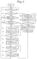
- Fig. 2 is a flow chart explaining an example of the operation of the diesel particulate filter, shown in Fig. 1.
- Fig. 3 is a sectional view showing the construction of a diesel particulate filter according to second embodiment of the present invention.
- Fig. 4 is a sectional view showing the construction of a main filter in the diesel particulate filter, shown in Fig. 3.
- Fig. 5 is a flow chart explaining an example of the operation of the diesel particulate filter, shown in Fig. 3.
- Fig. 1 is a sectional view of a particulate filter according to the first embodiment.
- a cylindrical bypass pipe 11 is disposed in a central portion within a heat resistant steel filter case 10, externally thereof is disposed a cylindrical laminated main filter 12 of a double co-axial tube construction, and further externally thereof is disposed a cylindrical exhaust pipe 13.
- the main filter 12 is made to be cylindrical in a section like a petal.
- the sub-filter 11a is constituted by a heat resistant metal pipe or a conductive ceramics pipe having a number of irregularly bent pores.
- Fe containing Ni and Cr is used on the surface of which is coated with ceramic.
- SiC can be used as a ceramic material.
- an inlet portion and a sub-filter portion can be constituted by materials different from each other.
- the whole bypass pipe 11 be also constituted by the same material.
- the main filter 12 comprises a heat resistant metal plate bored with a number of holes of air permeability are disposed, a ceramic fiber laminated body formed by superposing long fibers of ceramics which functions as a filter and wire net formed of heat resistant metal using Ni-Cr as main raw material are laminated.
- the ceramic fiber laminated body and the metal plate are laminated on the heat resistant metal plate and partly fastened.
- the heat resistant metal plate is positioned at a downstream layer in the exhaust flow.
- a ceramic net-like construction plate can be used in place of a heat resistant metal plate. Further, a fiber composite body formed of heat resistant metal fiber can be used in place of the ceramic fiber laminated body.
- Annular closed plates 14 for controlling a flow of exhaust gases are arranged between left end of the bypass pipe 11 and left end of the inner tube of the main filter 12, between left end of the outer tube of the main filter 12 and left end of the exhaust pipe 13, and between right ends of inner and outer tubes of the main filters 12.
- a bypass valve 15 for controlling passage/interception of exhaust gases is provided in the vicinity of an inlet of the bypass pipe 11.
- the bypass valve 15 is opened and closed by an actuator 18 through a valve operating arm 16 against of a force of the spring 17.
- the operation of the actuator 18 is controlled by a controller 19.
- An exhaust pressure sensor 20 for detecting pressure of exhaust gases on the inlet side is connected to the controller 19.
- bypass valve 15 Normally, the bypass valve 15 is closed while particulates are collected by the main filter 12 and exhaust gases do not pass through the bypass pipe 11. Exhaust gases come from the left side in the drawing, and the exhaust gases are fed between outer and inner tubes of the main filters 12, pass through the main filter 12, as shown by the arrows and thence are discharged outside of the main filter 12, as shown by arrows.
- the bypass valve 15 is opened by the actuator 18, and electric power is applied to the wire net laminated on main filter 12 for a fixed period of time to burn the particulates by the main filter 12. Thereafter, the bypass valve 15 is closed or slightly opened, under which state a small amount of air may flow into the bypass pipe 11, and electric power is applied to the sub-filter 11a to burn the particulates.
- an emergency valve is opened, irrespective of the state of the engine and a seat belt, to permit exhaust gases to flow out.
- Fig. 2 is a flow chart of assistance in explaining the operation of the particulate filter according to the embodiment.
- step S1 checking is made whether or not the clogging of the main filter 12 progresses up to a given level or more, that is, checking is made whether or not an exhaust gas pressure P exceeds a predetermined value P1. If exceeding the predetermined value P1, the step proceeds to step S2, otherwise the step returns to step S1.
- step S2 checking is made whether or not the clogging of the main filter 12 progresses up to an excessive level, that is, checking is made whether or not an exhaust gas pressure P exceeds a second predetermined value P2 (P1 ⁇ P2). If exceeding the predetermined value P2, the step proceeds to step S13, otherwise the step proceeds to step S3.
- step S3 checking is made whether or not the engine is in an idling state, that is, whether or not the number of revolutions of the engine is less than a predetermined number. In step S3, if judgement is made that the engine is in an idling state, the step proceeds to step S4, otherwise the step returns to step S1.
- step S4 checking is made whether or not seat belt is fastened. If in a "worn" state, judgement is made that the vehicle is running, and the step returns to step S1. If the seat belt is removed, open the bypass valve 15 (step S5) and start to energize the main filter 12 (step S6), after which the step proceeds to step S7.
- step S6 is executed, the combustion of particulates is carried out in the main filter 12. Since the bypass valve 15 is opened at this time, an amount of exhaust gases passing through the main filter 12 is reduced, the filter 12 is not cooled by the exhaust gases. Further, since the metal wire net or electric heating element is located at the upstream of the exhaust flow, the whole filter 12 is efficiently heated to enable the combustion without unevenness. Further, since the sub-filter 11a is disposed at the downstream portion of the bypass pipe 11, the exhaust gases not filtrated are not exhausted into atmosphere.
- step S7 checking is made whether or not a predetermined time (t1) after starting of combustion has passed. If not, the step returns to step S5. If the predetermined time (t1) has passed, the energization to the main filter 12 is turned off (step S8), and the bypass valve 15 is closed (step S9), after which the step proceeds to step S10 and the energization to the sub-filter 11a is started (step S10. Then the step proceeds to step S11.
- step S10 is executed, the combustion of particulates collected in the sub-filter 11a is carried out. At this time, the bypass valve 15 may be slightly opened to supply oxygen to the sub-filter 11a.
- step S11 checking is made whether or not the combustion in the sub-filter 11a was carried out for a predetermined time (t2). When a predetermined time has not been passed, the step returns to step S10. If a predetermined time (t2) has passed, the energization to the sub-filter 11a is turned off (step S12), after which the step returns to step S1.
- step S2 judgement was made that the clogging of the main filter 12 excessively progressed, the bypass valve 15 is immediately opened (step S13) without checking the state of the engine and the state of the seat belt, and the energization to the main filter 12 is started (step S14) is started, after which the step proceeds to step S15.
- step S15 checking is made whether or not a predetermined time (t3) after starting the combustion has passed. If not, the step returns to step S13. If a predetermined time (t3) has passed, the energization to the main filter 12 is turned off (step S16) and the bypass valve 15 is closed (step S17), after which the step returns to step S1.
- step S17 cleaning of the sub-filter 11a is carried out for a period of given time, and thereafter the step may return to step S1. Further, instead of carrying out the cleaning of the sub-filter 11a every time the main filter 12 is cleaned, it is so arranged that the sub-filter 11a may be cleaned when times of cleaning of the main filter reached a predetermined value.
- Fig. 3 is a sectional view of a particulate filter according to a second embodiment.
- a cylindrical bypass pipe 11 is disposed in a central portion within a steel filter case 10, and externally thereof is disposed a main cylindrical filter 31 including three tubes of different diameter which are coaxially arranged.
- Fig. 4 is a sectional view of a portion indicated at (A) in Fig. 3 of the main filter 31.
- the main filter 31 comprises a heat resistant metal plate 31a having a number of holes, a ceramics fiber composite 31b formed by placing long fibers of ceramics one upon another and sewing them together and a metal wire net 31c of elecric resistance as Ni-Cr.
- the ceramics fiber composite 31b performing a filter function is placed between the heat resistant metal plate 31a and the wire net 31c and the wire net 31c is placed in the upstream of the exhaust flow to receive the exhaust into the ceramics fiber compsite 31b.
- a ceramics net-like construction can be used in place of the heat resistant metal plate 31a, and a fiber composite formed of heat resistant metal fiber can be used in place of the ceramics fiber composite 31b.
- a bypass valve 15 for controlling passage/interception of exhaust gases is provided in the vicinity of an inlet of the bypass pipe 11.
- the bypass valve 15 is opened and closed by an actuator 18 through a valve operating arm 16a against a force of the spring 17.
- the operation of the actuator 18 is controlled by a controller 19.
- Input into the controller 19 are an output signal of a comparator 32 for comparing a electric resistance value between the wire net 31c (see Fig. 4) as an electric heating element and the net-like metal plate 31a with a reference value, and output signals of an idling sensor 22 which detects the number of revolutions of engine and a seat belt sensor 21 for detecting wearing and unwearing of a seat belt.
- the controller 19 further controls a supply of electric power to the wire net 31c by a control relay 33.
- bypass valve 15 Normally, the bypass valve 15 is closed and thus exhaust gases never pass through the bypass pipe 11. At this time, gases flown from the left side in the drawing are fed between the outer and inner cylidrical filters 31 or between the main filter 31 and the filter case 10, and pass through the main filter 12 as indicated at the arrows and thence are discharged outside of the main filters 31.
- the controller 19 receives output signals of the comparator 32 for detecting the resistance value between the wire net 31c as a heater provided on the main filter 31 and the metal plate 31a, output signals of the idling sensor 22 and output signals of the seat belt sensor 21 for detecting a neutral position of a gear in a transmission.
- the resistance value between the wire net 31c and the metal plate 31a gradually decreases as the particulates are accumlated in the ceramics fiber composite 31b.
- Fig. 5 is a flow chart of assistance in explaining the operation of the particulate filter according to the embodiment shown in Fig. 3.
- step S21 checking is made whether or not the clogging of the main filter 31 progresses up to a given level or more, that is, checking is made whether or not particulates collected by the wire net 31c reach a predetermined level or more, that is, an electric resistance value R of the wire net 31c is less than a predetermined value Ra. If the value R is less than the predetermined value Ra, the step proceeds to step S22, otherwise the step returns to step S21.
- step 22 checking is made whether or nor the engine is in an idling state or the gear position of the transmission is in a neutral state, that is, whether or not the number of revolutions of the engine is less than a predetermined number and the vehicle is in a stopped state.
- step S22 if judgement is made that the engine is in an idling state, the step proceeds to step S23, otherwise in step S29, the bypass valve 15 is opened. Then, in step S30, a filter clogging signal is generated, after which the step returns to step S21.
- step S29 is that when the combustion of particulates cannot be executed for the reason of the running of vehicle or the like despite the fact that the clogging of the main filter 31 proceeds to a predetermined level or more so that the exhaust gas pressure becomes higher than a the predetermined level, the bypass valve 15 is opened to spread a flow passage of exhaust gases so as not to impair the combustion. Further, step S30 is provided for the reason of informing a driver that since the clogging of the filter occurs, the combustion can be executed quickly as soon as the mode has moved to the combustible situation or environment. Informing means includes a buzzer, a display lamp, etc.
- step S23 checking is made whether or not a seat belt is fastened. If the seat belt is fastened, the program step open the bypass valve 15 (step S24), and start energization to the wire net 31c (step S25), and after this, proceeds to step S26.
- step S25 the combustion of particles is carried out.
- the bypass valve 15 is opened so that the amount of exhaust gases which pass through the main filter 31 is few, thus the main filter 31 is not cooled by the exhaust gases. Further, since the electric resistance element 31c is located at upstream of exhaust flow, the entire filter 31 is efficiently heated to enable even combustion.
- step S23 if judgement is made that the seat belt is unworn, the step proceeds to step S30. After a filter clogging signal has generated, the step returns to step S21.
- step S25 the electric resistance element 31c is started to be energized, and after this, in step S26, checking is made whether or not a predetermined time (t1) has passed after the start of combustion. When not passed, the step returns to step S24. When passed a predetermined time (t1), the bypass valve 15 is closed (step S27) and the energization to the electric resistance element 31c is turned off (step S28), after which the step returns to step S21.
- the present invention is not limited to the above-described embodiment but various changes can be made within the scope not changing the gist of the present invention.
- the fiber composite 31b can be constituted by woven textile of metal fiber and/or ceramics fibers.
- a bypass pipe for bypassing exhaust gases when particulate burn is provided within a filter case, and the bypass pipe is also made to have a filter function. Therefore, even if the particulate are burnt in the idling state of engine, the filter is not cooled by the exhaust gases to enable the performance of sufficient combustion.
Landscapes
- Engineering & Computer Science (AREA)
- Chemical & Material Sciences (AREA)
- Combustion & Propulsion (AREA)
- Mechanical Engineering (AREA)
- General Engineering & Computer Science (AREA)
- Processes For Solid Components From Exhaust (AREA)
Applications Claiming Priority (4)
| Application Number | Priority Date | Filing Date | Title |
|---|---|---|---|
| JP122990/94 | 1994-05-12 | ||
| JP6122989A JPH07310526A (ja) | 1994-05-12 | 1994-05-12 | ディーゼルパティキュレートフィルタとその制御装置 |
| JP122989/94 | 1994-05-12 | ||
| JP6122990A JPH07310527A (ja) | 1994-05-12 | 1994-05-12 | ディーゼルパティキュレートフィルタとその制御装置 |
Publications (3)
| Publication Number | Publication Date |
|---|---|
| EP0682174A2 true EP0682174A2 (de) | 1995-11-15 |
| EP0682174A3 EP0682174A3 (de) | 1995-11-22 |
| EP0682174B1 EP0682174B1 (de) | 1998-11-04 |
Family
ID=26460010
Family Applications (1)
| Application Number | Title | Priority Date | Filing Date |
|---|---|---|---|
| EP95303219A Expired - Lifetime EP0682174B1 (de) | 1994-05-12 | 1995-05-12 | Dieselpartikelfilter |
Country Status (3)
| Country | Link |
|---|---|
| US (1) | US5595580A (de) |
| EP (1) | EP0682174B1 (de) |
| DE (1) | DE69505729T2 (de) |
Cited By (8)
| Publication number | Priority date | Publication date | Assignee | Title |
|---|---|---|---|---|
| EP0699827B1 (de) * | 1994-08-29 | 1998-07-01 | Isuzu Ceramics Research Institute Co., Ltd. | Dieselpartikelfiltervorrichtung |
| EP0863398A1 (de) * | 1997-03-07 | 1998-09-09 | Institut Francais Du Petrole | Vorrichtung zum Nachweis der Verschmutzung einer isolierenden Umgebung, und zur lokalen Heizung dergleichen |
| EP0965736A3 (de) * | 1998-06-15 | 2001-10-10 | Delphi Technologies, Inc. | Abgaskatalysator mit Bypassströmung |
| WO2002048514A1 (fr) | 2000-12-14 | 2002-06-20 | Bernard Dias | DISPOSITIF DE TRAITEMENT DES GAZ D'ECHAPPEMENT POUR MOTEURS THERMIQUES |
| EP1914537A1 (de) * | 2006-10-17 | 2008-04-23 | Ibiden Co., Ltd. | Sensor für Partikel-Material |
| CN110465136A (zh) * | 2019-08-05 | 2019-11-19 | 江西博鑫精陶环保科技有限公司 | 一种功能性陶瓷纤维空气滤芯及其制备方法 |
| CN111173594A (zh) * | 2020-01-22 | 2020-05-19 | 天津大学 | 用于船舶尾气中颗粒物去除的装置 |
| WO2021070085A1 (en) | 2019-10-08 | 2021-04-15 | South Bank University Enterprises Ltd | Diesel particulate filtration system |
Families Citing this family (18)
| Publication number | Priority date | Publication date | Assignee | Title |
|---|---|---|---|---|
| JP4161546B2 (ja) * | 2001-06-26 | 2008-10-08 | いすゞ自動車株式会社 | 連続再生型ディーゼルパティキュレートフィルタ装置の再生制御方法 |
| US6948486B2 (en) * | 2002-06-28 | 2005-09-27 | Fleetguard, Inc. | System and method for derating an engine to encourage servicing of a vehicle |
| US6651638B1 (en) | 2002-06-28 | 2003-11-25 | Cummins Engine Company, Inc. | System and method for derating an engine to encourage servicing of a vehicle |
| JP2004036488A (ja) * | 2002-07-03 | 2004-02-05 | Honda Motor Co Ltd | 炭化水素吸着材の状態判定装置 |
| US6761155B2 (en) * | 2002-12-17 | 2004-07-13 | Caterpillar Inc | Separation membrane cartridge with bypass |
| JP4175282B2 (ja) * | 2004-03-31 | 2008-11-05 | いすゞ自動車株式会社 | 排気ガス浄化システムの制御方法及び排気ガス浄化システム |
| US8205441B2 (en) * | 2006-03-24 | 2012-06-26 | GM Global Technology Operations LLC | Zone heated inlet ignited diesel particulate filter regeneration |
| US20090025327A1 (en) * | 2007-03-26 | 2009-01-29 | Albracht Gregory P | Furring Strip Alignment System |
| US8671668B2 (en) | 2007-08-10 | 2014-03-18 | GM Global Technology Operations LLC | Generator powered electrically heated diesel particulate filter |
| US8388741B2 (en) | 2007-08-14 | 2013-03-05 | GM Global Technology Operations LLC | Electrically heated particulate filter with reduced stress |
| US8252077B2 (en) | 2007-09-17 | 2012-08-28 | GM Global Technology Operations LLC | Electrically heated particulate filter heater insulation |
| US7981174B2 (en) * | 2007-11-26 | 2011-07-19 | Caterpillar Inc. | Electrically regenerated exhaust particulate filter for an engine system and operating strategy therefor |
| US20090188389A1 (en) * | 2008-01-30 | 2009-07-30 | Caterpillar Inc. | Particulate filter for an exhaust aftertreatment system of a machine and filtering method thereof |
| CN101965511A (zh) * | 2008-02-27 | 2011-02-02 | 沃尔沃技术公司 | 用于检测粒子的方法及布置 |
| WO2013063137A1 (en) * | 2011-10-26 | 2013-05-02 | Boshart Automotive Testing Service, Inc. | Over temperature / pressure safety device for diesel particulate filters |
| WO2015171155A1 (en) * | 2014-05-09 | 2015-11-12 | Cummins Inc. | Techniques for minimizing aftertreatment system exhaust flow restrictions during engine operation |
| DE102019131892A1 (de) * | 2019-11-26 | 2021-05-27 | Bayerische Motoren Werke Aktiengesellschaft | Partikelfilter-Vorrichtung und Verfahren zur Filterung von Abgasen aus einem Verbrennungsmotor |
| CN111214877B (zh) * | 2020-03-02 | 2021-11-16 | 广西壮族自治区生态环境监测中心 | 一种分层处理污水装置 |
Family Cites Families (15)
| Publication number | Priority date | Publication date | Assignee | Title |
|---|---|---|---|---|
| US4264344A (en) * | 1980-02-06 | 1981-04-28 | General Motors Corporation | Diesel engine exhaust particulate trap |
| US4276066A (en) * | 1980-02-25 | 1981-06-30 | General Motors Corporation | Monolith diesel exhaust filter with self-regeneration |
| US4544388A (en) * | 1983-12-27 | 1985-10-01 | Ford Motor Company | Apparatus for periodically oxidizing particulates collected from exhaust gases |
| DE3622623A1 (de) * | 1986-07-05 | 1988-01-14 | Man Nutzfahrzeuge Gmbh | Verfahren und vorrichtung zum beseitigen von in einem abgasfilter einer brennkraftmaschine abgeschiedenem russ |
| US4969328A (en) * | 1986-10-21 | 1990-11-13 | Kammel Refaat A | Diesel engine exhaust oxidizer |
| US4813231A (en) * | 1987-10-07 | 1989-03-21 | Southwest Research Institute | Engine exhaust after-treatment device |
| JPH03141816A (ja) * | 1989-10-27 | 1991-06-17 | Toyota Motor Corp | 排気ガス浄化装置 |
| US5212948A (en) * | 1990-09-27 | 1993-05-25 | Donaldson Company, Inc. | Trap apparatus with bypass |
| AU2246092A (en) * | 1991-06-27 | 1993-01-25 | Donaldson Company Inc. | Trap apparatus with tubular filter element |
| US5228891A (en) * | 1992-01-07 | 1993-07-20 | Pall Corporation | Regenerable diesel exhaust filter |
| DE4212251C1 (de) * | 1992-04-11 | 1993-03-18 | Mercedes-Benz Aktiengesellschaft, 7000 Stuttgart, De | |
| US5224973A (en) * | 1992-04-20 | 1993-07-06 | Donaldson Company, Inc. | Filter cartridge for trap apparatus |
| KR960004832B1 (ko) * | 1992-08-24 | 1996-04-16 | 미쯔비시지도오샤고오교오 가부시기가이샤 | 배기가스정화장치 |
| US5458673A (en) * | 1992-11-26 | 1995-10-17 | Nippon Soken, Inc. | Exhaust gas particulate purifying process for internal combustion engine |
| US5423904A (en) * | 1993-05-28 | 1995-06-13 | Dasgupta; Sankar | Exhaust gas filter |
-
1995
- 1995-05-12 DE DE69505729T patent/DE69505729T2/de not_active Expired - Fee Related
- 1995-05-12 EP EP95303219A patent/EP0682174B1/de not_active Expired - Lifetime
- 1995-05-12 US US08/440,336 patent/US5595580A/en not_active Expired - Fee Related
Cited By (13)
| Publication number | Priority date | Publication date | Assignee | Title |
|---|---|---|---|---|
| EP0699827B1 (de) * | 1994-08-29 | 1998-07-01 | Isuzu Ceramics Research Institute Co., Ltd. | Dieselpartikelfiltervorrichtung |
| EP0863398A1 (de) * | 1997-03-07 | 1998-09-09 | Institut Francais Du Petrole | Vorrichtung zum Nachweis der Verschmutzung einer isolierenden Umgebung, und zur lokalen Heizung dergleichen |
| FR2760531A1 (fr) * | 1997-03-07 | 1998-09-11 | Inst Francais Du Petrole | Dispositif destine a detecter l'encrassement et a chauffer localement un milieu isolant |
| US6107603A (en) * | 1997-03-07 | 2000-08-22 | Institut Francais Du Petrole | Device intended to detect fouling and to locally heat an electrical insulating medium |
| EP0965736A3 (de) * | 1998-06-15 | 2001-10-10 | Delphi Technologies, Inc. | Abgaskatalysator mit Bypassströmung |
| WO2002048514A1 (fr) | 2000-12-14 | 2002-06-20 | Bernard Dias | DISPOSITIF DE TRAITEMENT DES GAZ D'ECHAPPEMENT POUR MOTEURS THERMIQUES |
| EP1914537A1 (de) * | 2006-10-17 | 2008-04-23 | Ibiden Co., Ltd. | Sensor für Partikel-Material |
| CN101165321B (zh) * | 2006-10-17 | 2010-06-02 | 揖斐电株式会社 | 微粒物质传感器 |
| US8127592B2 (en) | 2006-10-17 | 2012-03-06 | Ibiden Co., Ltd. | Particulate matter detection sensor |
| CN110465136A (zh) * | 2019-08-05 | 2019-11-19 | 江西博鑫精陶环保科技有限公司 | 一种功能性陶瓷纤维空气滤芯及其制备方法 |
| WO2021070085A1 (en) | 2019-10-08 | 2021-04-15 | South Bank University Enterprises Ltd | Diesel particulate filtration system |
| US11772079B2 (en) | 2019-10-08 | 2023-10-03 | South Bank University Enterprises Ltd. | Diesel particulate filtration (DPF) system |
| CN111173594A (zh) * | 2020-01-22 | 2020-05-19 | 天津大学 | 用于船舶尾气中颗粒物去除的装置 |
Also Published As
| Publication number | Publication date |
|---|---|
| US5595580A (en) | 1997-01-21 |
| EP0682174A3 (de) | 1995-11-22 |
| DE69505729T2 (de) | 1999-06-24 |
| DE69505729D1 (de) | 1998-12-10 |
| EP0682174B1 (de) | 1998-11-04 |
Similar Documents
| Publication | Publication Date | Title |
|---|---|---|
| US5595580A (en) | Diesel particulate filter and control device therefor | |
| US7987667B2 (en) | GPS-activated exhaust filtration monitoring and control system | |
| EP0699827B1 (de) | Dieselpartikelfiltervorrichtung | |
| US4335574A (en) | Carbon particles removing device | |
| EP0687805B1 (de) | Dieselpartikelfilter | |
| US4381643A (en) | Diesel exhaust cleaner and burner system with constant burner air mixture supply | |
| US4562695A (en) | Particulate trap system for engine exhaust using electrically powered regeneration | |
| EP0699828B1 (de) | Dieselpartikelfiltervorrichtung | |
| JPH05187221A (ja) | 排気微粒子浄化装置 | |
| JPH0868313A (ja) | ディーゼルパティキュレートフィルタの制御装置 | |
| US20080120961A1 (en) | Exhaust filtration monitoring and control system | |
| JP2003172117A (ja) | 2種類のセラミックス不織布を持つ排気ガス浄化装置 | |
| JP4382316B2 (ja) | 骨組用補強部材を備えた排気ガス浄化装置 | |
| JPH07310527A (ja) | ディーゼルパティキュレートフィルタとその制御装置 | |
| JP3713923B2 (ja) | ディーゼルパティキュレートフィルタの再生装置 | |
| JPH0771226A (ja) | 排気微粒子浄化装置 | |
| JPH0868310A (ja) | ディーゼルパティキュレートフィルタ装置 | |
| JPH07279646A (ja) | ディーゼルパティキュレートフィルタ | |
| JPH07310526A (ja) | ディーゼルパティキュレートフィルタとその制御装置 | |
| JP2918450B2 (ja) | ディーゼルパティキュレートフィルタにおけるフィルタ構造 | |
| JP2003172125A (ja) | 排気ガス浄化装置 | |
| WO1985002882A1 (en) | Particulate trap system for engine exhaust using electrically powered regeneration | |
| JPH06264722A (ja) | フィルタ装置 | |
| JP3075668B2 (ja) | ディーゼルパティキュレートフィルタにおけるフィルタ構造 | |
| JPH07310532A (ja) | ディーゼルパティキュレートフィルタ |
Legal Events
| Date | Code | Title | Description |
|---|---|---|---|
| PUAI | Public reference made under article 153(3) epc to a published international application that has entered the european phase |
Free format text: ORIGINAL CODE: 0009012 |
|
| PUAL | Search report despatched |
Free format text: ORIGINAL CODE: 0009013 |
|
| AK | Designated contracting states |
Kind code of ref document: A2 Designated state(s): DE FR GB |
|
| AK | Designated contracting states |
Kind code of ref document: A3 Designated state(s): DE FR GB |
|
| RHK1 | Main classification (correction) |
Ipc: F02N 3/02 |
|
| RHK1 | Main classification (correction) |
Ipc: F01N 3/02 |
|
| 17P | Request for examination filed |
Effective date: 19960112 |
|
| 17Q | First examination report despatched |
Effective date: 19970210 |
|
| GRAG | Despatch of communication of intention to grant |
Free format text: ORIGINAL CODE: EPIDOS AGRA |
|
| GRAG | Despatch of communication of intention to grant |
Free format text: ORIGINAL CODE: EPIDOS AGRA |
|
| GRAH | Despatch of communication of intention to grant a patent |
Free format text: ORIGINAL CODE: EPIDOS IGRA |
|
| GRAH | Despatch of communication of intention to grant a patent |
Free format text: ORIGINAL CODE: EPIDOS IGRA |
|
| GRAA | (expected) grant |
Free format text: ORIGINAL CODE: 0009210 |
|
| AK | Designated contracting states |
Kind code of ref document: B1 Designated state(s): DE FR GB |
|
| REF | Corresponds to: |
Ref document number: 69505729 Country of ref document: DE Date of ref document: 19981210 |
|
| ET | Fr: translation filed | ||
| PLBE | No opposition filed within time limit |
Free format text: ORIGINAL CODE: 0009261 |
|
| STAA | Information on the status of an ep patent application or granted ep patent |
Free format text: STATUS: NO OPPOSITION FILED WITHIN TIME LIMIT |
|
| 26N | No opposition filed | ||
| PGFP | Annual fee paid to national office [announced via postgrant information from national office to epo] |
Ref country code: FR Payment date: 20000414 Year of fee payment: 6 |
|
| PGFP | Annual fee paid to national office [announced via postgrant information from national office to epo] |
Ref country code: GB Payment date: 20000505 Year of fee payment: 6 |
|
| PGFP | Annual fee paid to national office [announced via postgrant information from national office to epo] |
Ref country code: DE Payment date: 20000627 Year of fee payment: 6 |
|
| PG25 | Lapsed in a contracting state [announced via postgrant information from national office to epo] |
Ref country code: GB Free format text: LAPSE BECAUSE OF NON-PAYMENT OF DUE FEES Effective date: 20010512 |
|
| GBPC | Gb: european patent ceased through non-payment of renewal fee |
Effective date: 20010512 |
|
| PG25 | Lapsed in a contracting state [announced via postgrant information from national office to epo] |
Ref country code: FR Free format text: LAPSE BECAUSE OF NON-PAYMENT OF DUE FEES Effective date: 20020131 |
|
| PG25 | Lapsed in a contracting state [announced via postgrant information from national office to epo] |
Ref country code: DE Free format text: LAPSE BECAUSE OF NON-PAYMENT OF DUE FEES Effective date: 20020301 |