EP0682440A2 - Verfahren und Vorrichtung zum Farbdruck unter Verwendung einer Farbtonbereichsumsetzung im Munsell Farbraum - Google Patents
Verfahren und Vorrichtung zum Farbdruck unter Verwendung einer Farbtonbereichsumsetzung im Munsell Farbraum Download PDFInfo
- Publication number
- EP0682440A2 EP0682440A2 EP95302174A EP95302174A EP0682440A2 EP 0682440 A2 EP0682440 A2 EP 0682440A2 EP 95302174 A EP95302174 A EP 95302174A EP 95302174 A EP95302174 A EP 95302174A EP 0682440 A2 EP0682440 A2 EP 0682440A2
- Authority
- EP
- European Patent Office
- Prior art keywords
- munsell
- gamut
- printer
- space
- points
- Prior art date
- Legal status (The legal status is an assumption and is not a legal conclusion. Google has not performed a legal analysis and makes no representation as to the accuracy of the status listed.)
- Granted
Links
- 238000013507 mapping Methods 0.000 title claims abstract description 71
- 238000000034 method Methods 0.000 title claims abstract description 28
- 239000003086 colorant Substances 0.000 claims abstract description 77
- 230000006870 function Effects 0.000 claims abstract description 29
- 238000005259 measurement Methods 0.000 claims description 10
- 230000001131 transforming effect Effects 0.000 claims description 9
- 230000003595 spectral effect Effects 0.000 claims description 4
- 238000010586 diagram Methods 0.000 description 11
- 230000000694 effects Effects 0.000 description 5
- 230000033458 reproduction Effects 0.000 description 5
- 230000006835 compression Effects 0.000 description 4
- 238000007906 compression Methods 0.000 description 4
- 230000004044 response Effects 0.000 description 3
- 238000012937 correction Methods 0.000 description 2
- 230000008569 process Effects 0.000 description 2
- 238000005070 sampling Methods 0.000 description 2
- 229920006395 saturated elastomer Polymers 0.000 description 2
- 230000007704 transition Effects 0.000 description 2
- 230000008859 change Effects 0.000 description 1
- 230000004456 color vision Effects 0.000 description 1
- 238000009792 diffusion process Methods 0.000 description 1
- 238000002474 experimental method Methods 0.000 description 1
- 238000013213 extrapolation Methods 0.000 description 1
- 238000009499 grossing Methods 0.000 description 1
- 238000003780 insertion Methods 0.000 description 1
- 230000037431 insertion Effects 0.000 description 1
- 238000007620 mathematical function Methods 0.000 description 1
- 230000003121 nonmonotonic effect Effects 0.000 description 1
- 230000002093 peripheral effect Effects 0.000 description 1
- 230000003068 static effect Effects 0.000 description 1
- 238000009827 uniform distribution Methods 0.000 description 1
Images


Classifications
-
- H—ELECTRICITY
- H04—ELECTRIC COMMUNICATION TECHNIQUE
- H04N—PICTORIAL COMMUNICATION, e.g. TELEVISION
- H04N1/00—Scanning, transmission or reproduction of documents or the like, e.g. facsimile transmission; Details thereof
- H04N1/46—Colour picture communication systems
- H04N1/56—Processing of colour picture signals
- H04N1/60—Colour correction or control
- H04N1/603—Colour correction or control controlled by characteristics of the picture signal generator or the picture reproducer
- H04N1/6033—Colour correction or control controlled by characteristics of the picture signal generator or the picture reproducer using test pattern analysis
-
- H—ELECTRICITY
- H04—ELECTRIC COMMUNICATION TECHNIQUE
- H04N—PICTORIAL COMMUNICATION, e.g. TELEVISION
- H04N1/00—Scanning, transmission or reproduction of documents or the like, e.g. facsimile transmission; Details thereof
- H04N1/46—Colour picture communication systems
- H04N1/56—Processing of colour picture signals
- H04N1/60—Colour correction or control
- H04N1/6058—Reduction of colour to a range of reproducible colours, e.g. to ink- reproducible colour gamut
Definitions
- the present invention pertains to a method and apparatus for building and using look-up tables which determine the colors that a color printer prints in response to requests to print specific colors.
- the specific colors requested to be printed may include colors that are not printable by the printer.
- gamut mapping is performed in Munsell color space where hue planes are straight, i.e. not curved, so as to compensate for the Abney effect and to preserve the perceived hue.
- color printers and color monitors form color images differently.
- a color monitor is a light emitting device; colors are formed on color monitors by adding light from three color primaries, generally, red, green and blue.
- Printed images on the other hand, simply reflect ambient light; colors are perceived by the way ambient light is affected by three subtractive primaries, generally cyan, magenta and yellow (and sometimes black).
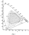
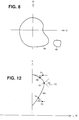
- Figure 1 is the CIE 1931 chromaticity diagram showing the range (or "gamut") of colors displayable by a monitor (area “A”) and the range (or “gamut") of colors printable by a printer (area “B”).
- the range of colors displayable on a monitor is generally greater than the range of colors printable by a printer. This is because a monitor is a light emitting device and is able to display colors with greater saturation. There are, however, some low saturation areas such as at area 10 where a printed image, which is light-subtractive, has greater color range than a monitor.
- out-of-gamut colors are adjusted to printable colors within the printer gamut by selecting the printable color which has the shortest vector distance from the unprintable color and which preserves the hue angle of the unprintable color.
- a line representing a constant hue or color drawn from pure white out to the fully saturated color is not a straight line but rather is a curved line.
- the curvature of those lines is shown in the chromaticity diagram of Figure 2. For regions where the curvature of constant hue lines is relatively low, like bluish-green region 18, preserving hue angle only slightly changes the perceived hue.
- preserving hue angle for the bluish-green out-of-gamut color 18a by extending the hue back to point 18b on the printer gamut border 10 still prints a bluish-green color. But for regions where the curvature of constant color lines is relatively high, like purplish-blue region 19, preserving hue angle greatly affects perceived hue. Thus, preserving hue angle for the blue out-of-gamut color 19a by extending hue back to point 19b on the printer gamut border 10 prints a color with a decidedly purplish-blue hue.
- out-of-gamut colors are printed with poor color smoothness, where small changes in commanded color can result in large changes in printed color.
- poor color smoothness manifests itself as non-monotonic changes in luminance whereby the lightnesses of out-of-gamut colors does not increase smoothly and monotonically from dark to light but rather dips occasionally from light to dark. This results in a situation where colors which should merge smoothly and monotonically from dark to light in fact show undesirable bands of darkness.
- a first aspect of the present invention addresses the foregoing difficulties and provides printer tables whose perceived hue is preserved and whose colors vary smoothly in the out-of-gamut regions by performing gamut mapping in Munsell space where the hue planes are straight.
- Munsell space is shown in Figure 4 where hue planes 5R, 5Y, 5G, 5B and 5P are shown projected into the U W plane at a constant value V as straight lines.
- Munsell coordinates are normally cylindrical coordinates H, V, C, but are shown in cartesian coordinates for a clearer understanding.
- the printer tables may be dervied once by a manufacturer, to be used in a printer driver which is sold to end users as part of a printer.
- the invention is a method and apparatus for building a printer table and a border table which give CMY values that are printed in response to a command to print a color.
- the CMY values inserted into the respective tables are determined in Munsell space. Since the gamut mapping takes place in Munsell space, the hue is exactly preserved by simply preserving the hue angle, and out-of-gamut colors vary smoothly and exhibit monotonic increase in lightnesses for increasingly lighter out-of-gamut colors.
- Color mapping functions are derived which map Munsell space coordinates into CMY coordinates.
- a Munsell printer gamut is determined by selecting points in Munsell space where the color mapping functions result within the printable CMY color range. All discrete points of an extended gamut in CIELAB space are mapped into the Munsell space.
- the extended gamut comprises colors within the printer gamut as well as colors outside the printer gamut such as colors typically found in a color monitor.
- CMY values are inserted into the color printer table by taking the mapped CIELAB points and applying the color mapping functions to the mapped CIELAB points that lie inside the Munsell printer gamut, and applying gamut mapping to the mapped CIELAB points in Munsell space that lie outside the Munsell printer gamut. Since the gamut mapping takes place in Munsell space, the hue is exactly preserved by simply preserving the hue angle.
- a border table may be provided for colors outside the extended gamut by mapping border points of the extended gamut, at all discrete angles and lightnesses, into the Munsell space and applying gamut mapping to the mapped CIELAB points in Munsell space.
- color printing is conducted by reference to the printer table and the border table, which give CMY values in response to a command to print a color.
- the printer table gives CMY values for colors within a printer table domain which consists of rectangular areas surrounding the extended gamut.
- the border table gives CMY values for colors outside the printer table domain.
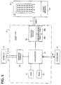
- Figure 5 is a block diagram of a printing apparatus according to the invention.
- the printing apparatus includes a host CPU 20, a color monitor 30 and a color printer 40.
- Host CPU 20 includes a processor 21 such as an 80586 microprocessor, a random access memory (“RAM”) 22 which provides working storage area to processor 21, a read only memory (“ROM”) 24 which provides static storage for processor 21, monitor driver 25 and a printer driver 26.
- Host CPU 20 is accessed by an operator via keyboard 27 which is connected through an interface 29 to processor 21. Using the keyboard, an operator can cause processor 21 to execute stored program instructions which cause color images to be displayed on monitor 30 and which cause corresponding color images to be printed on color printer 40.
- peripheral devices such as disk drives, tape drives, color video interfaces, color scanner interfaces, etc.
- Other peripheral devices such as disk drives, tape drives, color video interfaces, color scanner interfaces, etc.
- such devices permit, for example, a color image to be scanned into RAM 22 and displayed on monitor 30, the colors in the image to be manipulated, and the resulting image to be printed on printer 40.
- processor 21 derives a color image for display on monitor 30.
- Processor 21 provides the color image to monitor driver 25 which in turn derives RGB values for each pixel in monitor 30.
- the RGB values are provided via interface 31 to the monitor 30 where those values are displayed.
- processor 21 Upon request, processor 21 also feeds a color image to printer driver 26 for printing by color printer 40.
- Printer driver 26 derives CMY values for each pixel of the color image based on the color values provided from processor 21.
- the CMY values are determined in accordance with either the printer table 26a or the border table 26b.
- the printer table 26a is a table which provides CMY values for all colors that are printable by printer 40.
- the border table 26b is a table which provides suitable CMY values for colors that are not printable by printer 40.
- the printer table 26a may also include CMY values for some unprintable colors so as to smooth the transition from printable to unprintable colors. That is, printer table 26a has a domain which includes an extended gamut which includes the printer gamut and a typical color monitor gamut.
- a black (hereinafter "K") value may also be derived.
- the CMYK values are fed via interface 41 to printer 40 where they are stored in bit map memory 42 within printer 40.
- the bit map memory 42 may store a full bit map image of the printed image or it may store only a band or partial bit map image.
- a color printer head 44 reciprocates across a platen adjacent to a sheet of paper.
- print head 44 includes 32 ink jet nozzles which may be arranged in a four column by eight row pattern.
- the nozzles in the first column all eject droplets of cyan ink; the nozzles in the second column all eject droplets of magenta ink; the nozzles in the third column all eject droplets of yellow ink; and the nozzles in the fourth column all eject droplets of black ink.
- the nozzles are controlled independently in accordance with the color data in bit map memory 42 such that in one reciprocation of print head 44 across the platen, eight rows of pixels are printed.
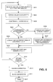
- FIG. 6 is a flow diagram showing how printer driver 26 selects CMYK values from the color data provided by processor 21.
- printer driver 26 receives RGB values for a location (x,y) in bit map memory 42.
- printer driver 26 drives device independent color coordinates from the RGB value.
- the device independent coordinates are CIELAB coordinates. This is because the coordinates in CIELAB space are perceptually uniform such that equal-sized intervals anywhere in CIELAB space correspond to equal-sized changes in perceived color.
- CIELAB space is one of the standard color spaces utilized in the printing industry.
- step S603 the luminance coordinate is compressed at the extremes of the L* axis in CIELAB space.
- compression step S603 is optional, it is nevertheless preferable to perform since it ensures that colors at extreme values of luminance are printed with perceptible changes in luminance. More particularly, because monitor 30 displays colors with light emitting elements, it can display colors with higher values of luminance then those achievable by printer 40, whose highest value of luminance is limited by the whiteness of the paper upon which the color image is formed. Further still, since monitor 30 can completely turn off its light emitting elements, it can display colors with lower values of luminance than those printable by printer 40, since even black ink reflects some ambient light. Accordingly, to ensure that some color is printed, even at the highest and lowest luminance values, it is preferable to compress the luminance values determined in step S602 into a range that is printable by printer 40.
- step S604 the L*, a* and b* coordinates derived in steps S602 and S603 are inspected to determine whether they fall within the range covered by printer table 26a. If the L*, a*, b* coordinates are within the range covered by printer table 26a, then flow advances to step S605 which looks up the corresponding CMY values in printer table 26a at location L*, a*, b* (actually, the nearest location since only discrete values of L*, a* and b* are stored).
- step S607 looks up corresponding CMY values in border table 26b at the nearest location which corresponds to the luminance L* and the hue angle derived in step S606.
- step S608 in which the CMY values are stored in bit map memory 42 at location (x,y).
- the CMY values may be modified before storage, for example, by interpolation, so as to accommodate the difference between the actual L*, a*, b* values stored in the tables and the desired values calculated above.
- step S609 printer driver 26 determines whether the bit map memory has been completed. If the bit map memory has not been completed, then flow returns to step S601 in which the next RGB value is received for the next location (x,y) in bit map memory. On the other hand, if the bit map memory has been completed, or if a sufficient area of the bit map memory has been completed (such as an eight row long band corresponding to the eight rows of ink jet nozzles in head 44), then flow advances to step S610 where gamma correction is performed. Gamma correction adjusts the CMY values in the bit map memory so as to achieve a uniform distribution of luminance. In step S611, undercolor removal in the present embodiment may be performed by the simple expedient of selecting the minimum value of CMY and assigning that value to the black value. Then, each of the CMY values is adjusted by subtracting the black value from it.
- steps S610 and S611 are not critical and those steps may be switched, for example to accommodate a particular color printing technique such as continuous tone, dither techniques or error diffusion.
- step S612 color printing is initiated using the resulting CMYK values.
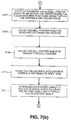
- Figures 7(a) - 7(d) when taken together as shown in Figure 7, comprise a flow diagram for describing how the printer table 26a and the border table 26b is constructed.
- the flow procedures shown in Figures 7(a) - 7(d) need only be performed once to derive printer tables and border tables for each printer.
- the printer tables are derived once by a manufacturer, to be used in a printer driver which is sold to end users as part of a printer.
- the printer tables may be in the form of software and/or hardware.
- the printer and border tables are CIELAB printer tables and CIELAB border tables because the RGB values received from an input device such as a scanner are generally transformed into CIELAB coordinates.
- the CMY values which are inserted into the CIELAB printer table and the CIELAB border table are computed in the Munsell space where hue planes are straight, to exactly preserve the hue by merely preserving the hue angle.
- the steps shown in the flow diagrams of Figure 8 may be stored program instructions which are operable in a CPU such as the CPU 20 shown in Figure 5, or the steps may be executed entirely in a special purpose hardware apparatus.
- step S701 relative spectral reflectance measurements are performed on the range of colors printable by printer 40.
- this is achieved by printing a very large subset, or a complete set, of all colors printable by printer 40.
- each of the CMY and K values may be printed in 65 gradations ranging numerically from 0 to 64. A subset of about one quarter of those values, for each color, are printed.
- Relative spectral reflectance measurements are performed on each of the 4,913 color patches and 48 additional gray patches.
- Step S702 transforms the measurements of printable colors into points in the CIELAB space with respect to CIE standard illuminant C in L*, a* and b* coordinates which are transformed into H, V, and C cylindrical coordinates in Munsell space in step S703.
- step S704 the cylindrical H, V, C coordinates in Munsell space are transformed to U, V, W cartesian coordinates, where the U, W plane is orthogonal to the V axis, with U pointing in the direction of the Munsell hue 10RP and W pointing in the direction of Munsell hue 5Y.
- Step S705 derives color mapping functions which map the Munsell coordinates into primary color coordinates, such as CMY coordinates.
- a cubic least square fit from Munsell space into CMY space was chosen. That is, using well-known least square fitting techniques, coefficients c0 through c19, m0 through m19, and y0 through y19 were derived to give the best fit, in the least squared sense, to the printable colors measured in step S701 and transformed in step S702:
- step S705 any mathematical function which fits the measurements taken in step S801 from the device independent coordinate space to CMY coordinate space may be used.
- the mapping function includes smoothing so as to eliminate measurement irregularities that may have been encountered in step S701.
- step S701 it may, in addition, be preferable to weight some of the points measured in step S701 prior to deriving mapping in step S705.
- proper skin tone color reproduction is an important property of color printers. Accordingly, it may be desirable, in some circumstances, to weight colors in the area of skin tone colors more heavily than other colors.
- step S706 the device independent space, namely Munsell space, is divided into equally sized discrete intervals, one of the intervals including the V axis such as by being centered at the V axis.
- the determining of the Munsell printer gamut is started in step S707 by determining the points where the color mapping functions result within the printable primary color range, i.e., the CMY values.
- the Munsell printer gamut is not the same for each value V. Specifically, the gamut is relatively smaller at value V extremes and relatively larger at the center of the value axis.
- step S708 and S709 the Munsell printer gamut is adjusted.
- the color matching function used may give rise to false regions in the Munsell printer gamut, such as region 45, which is not within the true Munsell printer gamut 46.
- These artifacts are removed in step S708 by removing all regions that are not connected to the region around the V axis.
- the Munsell printer gamut shown is not radially convex because each and every radial line from the V axis does not intersect border 47 at one and only one point.
- radial line 48 intersects border 47 at three points 49a, 49b and 49c.
- the region between points 49a and 49b is a radial concavity and can cause the generation of inappropriate CMY values. Accordingly, in step S709, the values in the Munsell printer gamut are adjusted to make them radially convex.
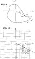
- Figure 10 illustrates this process.
- Figure 10 shows the rectangular grid in the U and W axis for an arbitrary luminance value V.
- Cells 51 through 55 all include printable values within the Munsell printer gamut.
- the printer table 26a and border table 26b provide CMY values in a device independent space, namely the CIELAB space.
- the CIELAB space Prior to later insertion of CMY values into these tables, the CIELAB space must be divided into equally sized discrete intervals, one of the intervals including the L* axis such as by being centered at the L* axis. In step S710 the CIELAB space is so divided.
- the extended gamut in the CIELAB space is determined by first determining the printer gamut in the CIELAB space and then selecting the extended gamut to be slightly larger than the printer gamut and a typical color monitor gamut.
- the printer gamut in the CIELAB space is determined by applying the color mapping functions which map the CIELAB coordinates into primary color coordinates, i.e. CMY coordinates, and making the CIELAB printer gamut connected to the L* axis and radially convex.
- step S712 all discrete points of the extended gamut in the CIELAB space are mapped into the Munsell Space.
- step S713 the border points of the extended gamut in the CIELAB space are mapped at all discrete angles and lightnesses into the Munsell space.
- Figure 11 shows the border points of the extended gamut 80 in the CIELAB space. In areas like the area 81 at the border of the extended gamut 80 between points 82 and 83, the saturation changes too much. To avoid this large saturation change when going from one discrete angle to the next, sufficiently fine angle changes have to be chosen. Increments of 1° have been found to be sufficiently fine.
- step S714 the size of the extended gamut in the CIELAB space is reduced, if necessary, so that the mapped points in the Munsell space are clearly defined Munsell colors, which means that they lie within the area of the Munsell color patches, or within the area of extrapolated Munsell colors.
- the extrapolation of Munsell colors is described in the "Final Report On The O.S.A. Subcommittee On The Spacing Of Munsell Colors" by Newhall, S. et al., J. Opt. Soc. Am., 33,7(1943).
- step S715 primary color values, i.e. CMY values are inserted into the CIELAB printer table around the L* axis by taking the mapped CIELAB printer table points and applying the color mapping functions to the mapped CIELAB points that lie inside the Munsell printer gamut, and applying gamut mapping to the mapped CIELAB points in Munsell space that lie outside the Munsell printer gamut.
- the gamut mapping maps a color point in the Munsell space which lies outside the Munsell printer gamut at a constant angle to a color of the same hue at the border of the Munsell printer gamut. Since gamut mapping takes place in the Munsell space, the hue is exactly preserved by simply preserving the hue angle.
- FIG. 12 a hue plane in the Munsell space is shown, and 60 is the border of the printer gamut.
- Each mapped point in the Munsell space that lies outside the Munsell printer gamut 60, such as the point 51 is gamut mapped at a constant angle ⁇ to a color of the same hue at a point on the border 60, such as point 52.
- the gamut mapping assigns to point 51 the CMY color of point 52, which is determined by applying the color mapping functions to point 52.
- a mapped point 53 outside the Munsell printer gamut 60 is gamut mapped at the constant angle ⁇ to a color of the same hue at point 54 on the border 60.
- the gamut mapping assigns to point 53 the CMY color of point 54, which is determined by applying the color mapping functions to point 54.
- the angle ⁇ lies in the range of approximately 10° to 30° with respect to the lightnesses plane at the points 51 or 53.
- point 50 denotes the point of maximum saturation at the border 60 of the Munsell printer gamut.
- the angle ⁇ extends downwardly; and for points below the point 50, such as the point 53, the angle ⁇ extends upwardly.
- All mapped points in the wedge 70, subtended by the angle 2 ⁇ from the point 50 are gamut mapped to the color at point 50.
- the gamut mapping assigns to all points in the wedge 70 the CMY color of point 50, which is determined by applying the color mapping functions to point 50. Since the gamut mapping preserves the hue angle in Munsell space, the hue is exactly preserved.
- CMY values are inserted into the printer table at the L* axis by determining the printer grays.
- CMY values are inserted into the border table by taking the mapped CIELAB border points of the extended gamut and applying the gamut mapping as shown in Figure 11.
- the border table lists one primary CMY color at all discrete angles and lightnesses for points outside the extended gamut in CIELAB space. These primary colors are determined by mapping the border points of the extended gamut in CIELAB space at all discrete angles and lightnesses into the Munsell space and applying the gamut mapping in the Munsell space as described relative to Figure 12.
- Figure 15 shows the correspondence of border tables and printer tables.
- printer table 26a is a rectangular grid for an arbitrary luminance value L*
- Individual cells in the border table are accessed by the angle ⁇ in the a* b* plane which also corresponds to hue.
- ⁇ the angle in the a* b* plane which also corresponds to hue.
- step S7108 the printer table is rectangularized. More specifically, until this step, CMY values have been inserted into the printer table only in areas within the extended gamut 61 which includes the printer gamut 60 (steps S710 and S715).
- step S718, the remaining cells of the printer table such as cells like cell 68 in Figure 15 are filled out by calculating the hue angle for each blank cell that remains in the printer table and by inserting the border table color at that hue angle as illustrated at 69 in Figure 15.
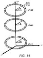
- the border table is arranged in wheels with one wheel for each of the luminance values of the printer table.
- a wheel-shaped border table is provided for each of the luminance values for which a printer table exists, which provides one border table in correspondence with each of the printer tables.
- Figure 13 illustrates a typical division of CIELAB space into a printer table, although all luminance and hue gradations have not been shown to simplify the presentation.
Landscapes
- Engineering & Computer Science (AREA)
- Multimedia (AREA)
- Signal Processing (AREA)
- Color Image Communication Systems (AREA)
- Facsimile Image Signal Circuits (AREA)
- Processing Or Creating Images (AREA)
- Record Information Processing For Printing (AREA)
- Color, Gradation (AREA)
Applications Claiming Priority (2)
| Application Number | Priority Date | Filing Date | Title |
|---|---|---|---|
| US242234 | 1994-05-13 | ||
| US08/242,234 US5574666A (en) | 1994-05-13 | 1994-05-13 | Color printing method and apparatus using gamut mapping in Munsell space |
Publications (3)
| Publication Number | Publication Date |
|---|---|
| EP0682440A2 true EP0682440A2 (de) | 1995-11-15 |
| EP0682440A3 EP0682440A3 (de) | 1996-03-06 |
| EP0682440B1 EP0682440B1 (de) | 2000-09-13 |
Family
ID=22913983
Family Applications (1)
| Application Number | Title | Priority Date | Filing Date |
|---|---|---|---|
| EP95302174A Expired - Lifetime EP0682440B1 (de) | 1994-05-13 | 1995-03-31 | Verfahren und Vorrichtung zum Farbdruck unter Verwendung einer Farbtonbereichsumsetzung im Munsell Farbraum |
Country Status (4)
| Country | Link |
|---|---|
| US (1) | US5574666A (de) |
| EP (1) | EP0682440B1 (de) |
| JP (1) | JP3599417B2 (de) |
| DE (1) | DE69518790T2 (de) |
Cited By (2)
| Publication number | Priority date | Publication date | Assignee | Title |
|---|---|---|---|---|
| DE10110125A1 (de) * | 2001-03-02 | 2002-09-19 | Heidelberger Druckmasch Ag | Verfahren zur Bestimmung eines Farbprofils für das drucken mit N Druckfarben |
| EP1553787A3 (de) * | 2004-01-12 | 2009-06-24 | Lg Electronics Inc. | Farbwiedergabevorrichtung und Einrichtung zum Steuern eines Anzeigegeräts |
Families Citing this family (25)
| Publication number | Priority date | Publication date | Assignee | Title |
|---|---|---|---|---|
| US5715073A (en) * | 1995-02-03 | 1998-02-03 | Eastman Kodak Company | Processing by separate stages monochrome digital images to provide halftone color images |
| US6229915B1 (en) * | 1996-08-22 | 2001-05-08 | Fuji Photo Film Co., Ltd. | Method of converting data of a first colorimetric system to data of a second colorimetric system, including a mapping of out of boundary data |
| US5987168A (en) * | 1997-03-25 | 1999-11-16 | International Business Machines Corporation | System, method, and program for converting three dimensional colorants to more than three dimensional colorants |
| US6229626B1 (en) | 1997-10-24 | 2001-05-08 | Eastman Kodak Company | Method apparatus and product providing direct calculation of the color gamut of color reproduction processes |
| US6441869B1 (en) * | 1999-08-27 | 2002-08-27 | Xerox Corporation | Systems and methods for color specific hue control |
| US6724500B1 (en) | 1999-11-29 | 2004-04-20 | Xerox Corporation | Piecewise color transformation by gamut partitioning |
| US6625306B1 (en) * | 1999-12-07 | 2003-09-23 | Xerox Corporation | Color gamut mapping for accurately mapping certain critical colors and corresponding transforming of nearby colors and enhancing global smoothness |
| US6775028B1 (en) | 2000-02-24 | 2004-08-10 | Lexmark International, Inc. | Non-linear method of mapping the lightness and chroma of a display device gamut onto a printing device gamut |
| US6972869B2 (en) * | 2000-12-18 | 2005-12-06 | Xerox Corporation | Mapping color to colorant amounts when colorants have similar hue |
| KR100416231B1 (ko) * | 2001-11-08 | 2004-01-31 | 한국전자통신연구원 | 칼라 디바이스의 선형 색역폭 확장장치 및 그 방법 |
| US6956581B2 (en) * | 2002-09-19 | 2005-10-18 | Lexmark International, Inc. | Gamut mapping algorithm for business graphics |
| US7283662B1 (en) | 2002-11-19 | 2007-10-16 | Adobe System Incorporated | Protecting colors from clipping |
| US7583406B2 (en) * | 2005-08-23 | 2009-09-01 | Eastman Kodak Company | Color transforms for concave device gamuts |
| US7893945B2 (en) * | 2006-08-21 | 2011-02-22 | Texas Instruments Incorporated | Color mapping techniques for color imaging devices |
| JP4827713B2 (ja) * | 2006-12-12 | 2011-11-30 | キヤノン株式会社 | 色処理装置、色処理方法及びプログラム |
| JP4893536B2 (ja) * | 2007-08-27 | 2012-03-07 | ブラザー工業株式会社 | 色域情報作成装置、色域情報作成方法および色域情報作成プログラム |
| US8351100B2 (en) * | 2008-05-28 | 2013-01-08 | Xerox Corporation | Method to create spot colors with white and CMYK toner and achieve color consistency |
| US20100156929A1 (en) * | 2008-12-23 | 2010-06-24 | Eastman Kodak Company | Ridge-based color gamut mapping |
| JP5116866B2 (ja) * | 2011-07-19 | 2013-01-09 | キヤノン株式会社 | 色処理装置、色処理方法、及びプログラム |
| US9565596B2 (en) * | 2011-08-29 | 2017-02-07 | Commscope Technologies Llc | Configuring a distributed antenna system |
| US20170111551A1 (en) * | 2014-06-06 | 2017-04-20 | Hewlett-Packard Development Company, L.P. | Modifying color gamuts |
| CN104537626B (zh) * | 2015-01-04 | 2017-09-12 | 上海理工大学 | Cielab颜色系统向孟塞尔色序系统的转换方法 |
| EP3367659A1 (de) * | 2017-02-28 | 2018-08-29 | Thomson Licensing | Farbtonbereichsumsetzung für farbtonänderung |
| US10630867B2 (en) | 2018-09-17 | 2020-04-21 | Samsung Electronics Co., Ltd. | Perceptual hue preserved color-gamut transferring in non-uniform CIE-1931 color space |
| US11348553B2 (en) | 2019-02-11 | 2022-05-31 | Samsung Electronics Co., Ltd. | Color gamut mapping in the CIE 1931 color space |
Citations (1)
| Publication number | Priority date | Publication date | Assignee | Title |
|---|---|---|---|---|
| US5299291A (en) | 1992-10-05 | 1994-03-29 | Canon Information Systems | Color printing method and apparatus using an out-of-gamut color table |
Family Cites Families (23)
| Publication number | Priority date | Publication date | Assignee | Title |
|---|---|---|---|---|
| US3825673A (en) * | 1971-03-04 | 1974-07-23 | Warwick Electronics Inc | Color gamut compressor |
| US4620792A (en) * | 1984-04-06 | 1986-11-04 | Nagaichi Suga | Method of simply setting expansion regions for conversion of values of colors according to xyz notation system into values of colors according to Munsell notation system |
| US4751535A (en) * | 1986-10-15 | 1988-06-14 | Xerox Corporation | Color-matched printing |
| US4941038A (en) * | 1987-05-11 | 1990-07-10 | The Mead Corporation | Method for color image processing |
| ES2059096T3 (es) * | 1990-03-02 | 1994-11-01 | Ciba Geigy Ag | Procedimiento para la determinacion de recetas de tintura e impresion segun una muestra de color. |
| GB9005030D0 (en) * | 1990-03-06 | 1990-05-02 | Crosfield Electronics Ltd | Image data processing |
| US5239370A (en) * | 1990-04-24 | 1993-08-24 | Brother Kogyo Kabushiki Kaisha | Color image forming apparatus having color-correcting unit operating in accordance with a gamut of an image input medium |
| US5282046A (en) * | 1990-07-25 | 1994-01-25 | Brother Kogyo Kabushiki Kaisha | Color image forming apparatus having a color-correcting unit |
| US5287122A (en) * | 1990-08-23 | 1994-02-15 | Schlumberger Technology Corporation | System and method of selecting the reproducible colors in a discrete reproduction system |
| US5237517A (en) * | 1990-08-29 | 1993-08-17 | Xerox Corporation | Color printing having a highlight color image mapped from a full color image |
| US5237409A (en) * | 1990-09-10 | 1993-08-17 | Brother Kogyo Kabushiki Kaisha | Color image forming apparatus using color compressed color data |
| CA2055058C (en) * | 1990-12-31 | 1996-08-06 | Anthony Joseph Dattilo | Automatic correction for color printing |
| BE1004659A5 (nl) * | 1991-03-01 | 1993-01-05 | Barco Graphics Nv | Werkwijze en inrichting voor het transformeren van een kleurcoordinatenset. |
| US5243414A (en) * | 1991-07-29 | 1993-09-07 | Tektronix, Inc. | Color processing system |
| US5185661A (en) * | 1991-09-19 | 1993-02-09 | Eastman Kodak Company | Input scanner color mapping and input/output color gamut transformation |
| US5257097A (en) * | 1991-09-27 | 1993-10-26 | Eastman Kodak Company | Method and apparatus for selective interception of a graphics rendering operation for effecting image data modification |
| US5416890A (en) * | 1991-12-11 | 1995-05-16 | Xerox Corporation | Graphical user interface for controlling color gamut clipping |
| US5231504A (en) * | 1991-12-30 | 1993-07-27 | Xerox Corporation | Method for improved color reproduction using linear mixing calculations based on positional relationships between an original color and an achromatic region in a linear mixing space |
| US5317425A (en) * | 1992-02-10 | 1994-05-31 | Eastman Kodak Company | Technique for use in conjunction with an imaging system for providing an appearance match between two images and for calibrating the system thereto |
| US5343311A (en) * | 1992-04-14 | 1994-08-30 | Electronics For Imaging, Inc. | Indexed processing of color image data |
| US5333243A (en) * | 1992-05-04 | 1994-07-26 | Hewlett-Packard Company | Method for forming color images, using a hue-plus-gray color model and error diffusion |
| US5377025A (en) * | 1992-11-24 | 1994-12-27 | Eastman Kodak Company | Optimal color quantization for addressing multi-dimensional color calibration look-up-table |
| US5323249A (en) * | 1993-01-12 | 1994-06-21 | E. I. Du Pont De Nemours And Company | Method for reproducing color images having one color gamut with a device having a different color gamut |
-
1994
- 1994-05-13 US US08/242,234 patent/US5574666A/en not_active Expired - Lifetime
-
1995
- 1995-03-31 DE DE69518790T patent/DE69518790T2/de not_active Expired - Lifetime
- 1995-03-31 EP EP95302174A patent/EP0682440B1/de not_active Expired - Lifetime
- 1995-05-10 JP JP11183695A patent/JP3599417B2/ja not_active Expired - Fee Related
Patent Citations (1)
| Publication number | Priority date | Publication date | Assignee | Title |
|---|---|---|---|---|
| US5299291A (en) | 1992-10-05 | 1994-03-29 | Canon Information Systems | Color printing method and apparatus using an out-of-gamut color table |
Cited By (3)
| Publication number | Priority date | Publication date | Assignee | Title |
|---|---|---|---|---|
| DE10110125A1 (de) * | 2001-03-02 | 2002-09-19 | Heidelberger Druckmasch Ag | Verfahren zur Bestimmung eines Farbprofils für das drucken mit N Druckfarben |
| US7233412B2 (en) | 2001-03-02 | 2007-06-19 | Heidelberger Druckmaschinen Ag | Method of determining a color profile for printing with N printing inks |
| EP1553787A3 (de) * | 2004-01-12 | 2009-06-24 | Lg Electronics Inc. | Farbwiedergabevorrichtung und Einrichtung zum Steuern eines Anzeigegeräts |
Also Published As
| Publication number | Publication date |
|---|---|
| DE69518790T2 (de) | 2001-02-22 |
| EP0682440B1 (de) | 2000-09-13 |
| JP3599417B2 (ja) | 2004-12-08 |
| EP0682440A3 (de) | 1996-03-06 |
| DE69518790D1 (de) | 2000-10-19 |
| JPH07323614A (ja) | 1995-12-12 |
| US5574666A (en) | 1996-11-12 |
Similar Documents
| Publication | Publication Date | Title |
|---|---|---|
| US5574666A (en) | Color printing method and apparatus using gamut mapping in Munsell space | |
| US5500921A (en) | Method and apparatus for printing high fidelity color reproductions of colors displayed on a monitor | |
| EP0592146B1 (de) | Farbraumtransformation für die Farbbild-Reproduktion | |
| EP0592147B1 (de) | Verfahren und Vorrichtung zur Reproduktion von Farbbildern | |
| US5699491A (en) | Printer driver having gamut-mapped colors | |
| EP0990344B1 (de) | Farbtonkorrektur mit farbtrennung sowie verfahren und apparate zur durchführung | |
| US7864371B2 (en) | Image processing apparatus, image processing method, and computer product | |
| US6724500B1 (en) | Piecewise color transformation by gamut partitioning | |
| EP1404117B1 (de) | Bildverarbeitungseinrichtung, bildverarbeitungsverfahren, programm und aufzeichnungsmedium | |
| JPH07222019A (ja) | 印字装置 | |
| JPH07212607A (ja) | カラー・イメージ生成システムおよび方法 | |
| US7126718B1 (en) | Adjustment of color appearance models | |
| JP3880587B2 (ja) | 色処理装置およびその方法 | |
| JP2005295153A (ja) | 色変換装置およびその方法 | |
| JP4380503B2 (ja) | ルックアップテーブル作成方法および分版方法 | |
| JPH06225132A (ja) | 色域外カラーテーブルを用いたカラー印刷方法及び装置 | |
| JP2003283851A (ja) | 印刷制御装置、印刷制御方法、印刷制御プログラム、印刷制御プログラムを記録した媒体、色変換装置、色変換方法、色変換テーブルの作成方法および色変換テーブル | |
| JPH07222020A (ja) | 印字装置 |
Legal Events
| Date | Code | Title | Description |
|---|---|---|---|
| PUAI | Public reference made under article 153(3) epc to a published international application that has entered the european phase |
Free format text: ORIGINAL CODE: 0009012 |
|
| AK | Designated contracting states |
Kind code of ref document: A2 Designated state(s): DE FR GB IT |
|
| PUAL | Search report despatched |
Free format text: ORIGINAL CODE: 0009013 |
|
| AK | Designated contracting states |
Kind code of ref document: A3 Designated state(s): DE FR GB IT |
|
| 17P | Request for examination filed |
Effective date: 19960717 |
|
| 17Q | First examination report despatched |
Effective date: 19980525 |
|
| GRAG | Despatch of communication of intention to grant |
Free format text: ORIGINAL CODE: EPIDOS AGRA |
|
| GRAG | Despatch of communication of intention to grant |
Free format text: ORIGINAL CODE: EPIDOS AGRA |
|
| GRAG | Despatch of communication of intention to grant |
Free format text: ORIGINAL CODE: EPIDOS AGRA |
|
| GRAH | Despatch of communication of intention to grant a patent |
Free format text: ORIGINAL CODE: EPIDOS IGRA |
|
| GRAH | Despatch of communication of intention to grant a patent |
Free format text: ORIGINAL CODE: EPIDOS IGRA |
|
| GRAA | (expected) grant |
Free format text: ORIGINAL CODE: 0009210 |
|
| AK | Designated contracting states |
Kind code of ref document: B1 Designated state(s): DE FR GB IT |
|
| PG25 | Lapsed in a contracting state [announced via postgrant information from national office to epo] |
Ref country code: IT Free format text: LAPSE BECAUSE OF FAILURE TO SUBMIT A TRANSLATION OF THE DESCRIPTION OR TO PAY THE FEE WITHIN THE PRESCRIBED TIME-LIMIT;WARNING: LAPSES OF ITALIAN PATENTS WITH EFFECTIVE DATE BEFORE 2007 MAY HAVE OCCURRED AT ANY TIME BEFORE 2007. THE CORRECT EFFECTIVE DATE MAY BE DIFFERENT FROM THE ONE RECORDED. Effective date: 20000913 |
|
| REF | Corresponds to: |
Ref document number: 69518790 Country of ref document: DE Date of ref document: 20001019 |
|
| ET | Fr: translation filed | ||
| REG | Reference to a national code |
Ref country code: GB Ref legal event code: 732E |
|
| PLBE | No opposition filed within time limit |
Free format text: ORIGINAL CODE: 0009261 |
|
| STAA | Information on the status of an ep patent application or granted ep patent |
Free format text: STATUS: NO OPPOSITION FILED WITHIN TIME LIMIT |
|
| 26N | No opposition filed | ||
| REG | Reference to a national code |
Ref country code: GB Ref legal event code: IF02 |
|
| PGFP | Annual fee paid to national office [announced via postgrant information from national office to epo] |
Ref country code: GB Payment date: 20020318 Year of fee payment: 8 |
|
| PGFP | Annual fee paid to national office [announced via postgrant information from national office to epo] |
Ref country code: FR Payment date: 20020325 Year of fee payment: 8 |
|
| REG | Reference to a national code |
Ref country code: FR Ref legal event code: TP |
|
| PG25 | Lapsed in a contracting state [announced via postgrant information from national office to epo] |
Ref country code: GB Free format text: LAPSE BECAUSE OF NON-PAYMENT OF DUE FEES Effective date: 20030331 |
|
| GBPC | Gb: european patent ceased through non-payment of renewal fee |
Effective date: 20030331 |
|
| PG25 | Lapsed in a contracting state [announced via postgrant information from national office to epo] |
Ref country code: FR Free format text: LAPSE BECAUSE OF NON-PAYMENT OF DUE FEES Effective date: 20031127 |
|
| REG | Reference to a national code |
Ref country code: FR Ref legal event code: ST |
|
| PGFP | Annual fee paid to national office [announced via postgrant information from national office to epo] |
Ref country code: DE Payment date: 20140331 Year of fee payment: 20 |
|
| REG | Reference to a national code |
Ref country code: DE Ref legal event code: R071 Ref document number: 69518790 Country of ref document: DE |