EP0682462A2 - Dispositif de contrôle de la position d'un élément chauffant dans un four in microondes - Google Patents
Dispositif de contrôle de la position d'un élément chauffant dans un four in microondes Download PDFInfo
- Publication number
- EP0682462A2 EP0682462A2 EP95303192A EP95303192A EP0682462A2 EP 0682462 A2 EP0682462 A2 EP 0682462A2 EP 95303192 A EP95303192 A EP 95303192A EP 95303192 A EP95303192 A EP 95303192A EP 0682462 A2 EP0682462 A2 EP 0682462A2
- Authority
- EP
- European Patent Office
- Prior art keywords
- heater
- power
- microwave oven
- rotated
- position control
- Prior art date
- Legal status (The legal status is an assumption and is not a legal conclusion. Google has not performed a legal analysis and makes no representation as to the accuracy of the status listed.)
- Withdrawn
Links
Images


Classifications
-
- H—ELECTRICITY
- H05—ELECTRIC TECHNIQUES NOT OTHERWISE PROVIDED FOR
- H05B—ELECTRIC HEATING; ELECTRIC LIGHT SOURCES NOT OTHERWISE PROVIDED FOR; CIRCUIT ARRANGEMENTS FOR ELECTRIC LIGHT SOURCES, IN GENERAL
- H05B6/00—Heating by electric, magnetic or electromagnetic fields
- H05B6/64—Heating using microwaves
- H05B6/647—Aspects related to microwave heating combined with other heating techniques
- H05B6/6482—Aspects related to microwave heating combined with other heating techniques combined with radiant heating, e.g. infrared heating
-
- F—MECHANICAL ENGINEERING; LIGHTING; HEATING; WEAPONS; BLASTING
- F24—HEATING; RANGES; VENTILATING
- F24C—DOMESTIC STOVES OR RANGES ; DETAILS OF DOMESTIC STOVES OR RANGES, OF GENERAL APPLICATION
- F24C7/00—Stoves or ranges heated by electric energy
- F24C7/06—Arrangement or mounting of electric heating elements
Definitions
- the present invention relates to a microwave oven employing a magnetron and a heater for performing an oven cook function, a grill cooking function, a convection cooking function and a combination cooking function.
- a microwave oven equipped with a magnetron and a heater for performing an oven cooking function, a grill cooking function, convection cooking function and a combination cooking function has been disclosed in various forms.
- the Japanese patent publication No. Sho 62-60617 as illustrated in Figure 1, includes a heating chamber A, a high frequency oscillator 4, a sensor 5 for detecting humidity of food heated by the high frequency oscillator 4 or for detecting concentrated degree of gas, and a heater 6 for heating the food, whereby the sensor 5 is disposed near the heater 6 in order to directly receive radiant heat of the heater 6.
- the conventional microwave oven cannot easily grill-cook the food because the heater 6 is fixedly disposed within the heating chamber A, and a ceiling of the heating chamber A cannot within the heating chamber A, and a ceiling of the heating chamber A cannot be simply cleaned when an interior of the heating chamber A is to be cleaned.
- the present invention is therefore disclosed to solve the aforesaid problems and it is an object of the present invention to provide a heater position control apparatus of a microwave oven by which position of a heater can be automatically moved to a place where a user requires, to thereby cause the food to be easily cooked and to cause a cooking chamber to be easily cleaned.
- a heater position control apparatus of a microwave oven is provided by which a heater position can be changed to a place where a user requires when food is cooked or a cooking chamber is cleaned, to thereby cause the food to be easily cooked, and at the same time, to cause the cooking chamber to be easily cleaned, while construction thereof is simple to thereby reduce the manufacturing cost and to improve productivity as well.
- a heater position control apparatus of a microwave oven employing a body constituting an enclosure thereof and a cooking chamber formed by a cavity within the body, the apparatus comprising: a heater disposed at the cooking chamber to thereby be rotated therein; power generating means for being fixed to one side of the cavity in order to generate an operating power for rotation of the heater; power transmission means for transferring the power generated from the power generating means; and heater supporting means for being rotated by the power transmitted from the power transmission means to thereby support the heater.
- the user can easily change a position of the heater to a place where it is required and at the same time, the food can be easily cooked because the heat generated from the heater is forcibly circulated within the cooking chamber, and the cooking chamber can be easily cleaned.
- construction thereof is compactly made up so that a manufacturing cost can be reduced and productivity can be increased.
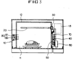
- reference numeral 10 denotes a body of the microwave oven wherein a cavity 12 constituting a cooking chamber 11 is inherently disposed so as to perform an oven cooking, grill cooking, convection cooking or a combination cooking.
- a magnetron 13 for oscillating the high frequency to thereby cause the food to be oven-cooked and a heater 20 for generating the heat to thereby cause the food to be grill-cooked.
- the cavity 12 for constituting the cooking chamber 11 of the body 10 is formed at one side thereof with power generating means 60 for generating the power so that the heater 20 can be moved by a control signal of control means (not shown), power transmission means 40 for transferring the power generated from the power generating means 60, heater supporting means 30 for being rotated by the power transferred by the power transmission means 40 to thereby support the heater 20, and position sensing means 70 for being fixed to one side of the power transmission means 40 so that a moved position of the heater 20 supported by the heater supporting means 30 can be discriminated to thereby deactivate the power generating means 60.
- the cavity 12 is fixed at one side of the body 10 with a support member 50 as a mounting for the power generating means 60 for generating the power by the control signal of the control means (not shown) in order to move the heater 20.
- the support member 50 is disposed with the power transmission means 40 for transferring the power generated from the power generating means 60 so that the heater 20 can be moved.
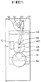
- the power transmission means 40 includes a first gear member 41 for being inserted into a shaft 61 of the power generating means 60 to thereby be rotated by the power of the power generating means 60, a second gear member 42 with a protrusion 421 thereon for being meshed into the first gear member 41 and for being rotated in cooperation with the first gear member 41, and a transmission member 44 for being fixed at one end thereof to the protrusion 421 of the second gear member 42 and for being fixed at the other end thereof to the heater supporting means 30, to thereby transfer rotation of the second gear member 42 to the heater supporting means 30, whereby the power generated from the power generating means 60 can be transferred to the heater supporting means 30 to thereby move the position of the heater 20.
- the second gear member 42 is meshed into a support shaft 43 mounted on the support member 50 to thereby be rotated in cooperation with the first gear member 41.
- the heater supporting means 30 includes a hole 311 through which one end of the heater 20 passes, a flange member 31 formed with a top hole 312, a bracket member 33 for being fixed to the flange member 31 by a fixing member 34 such as bolt or the like so that the flange member 31 can be rotated, with a protrusion 331 so that one end of the transmission member 44 can be contacted, and a support member 32 for maintaining a gap between the bracket member 33 and the flange member 31 so that both members 31 and 33 can be easily rotated.
- the bracket member 33 is formed with an opening unit 332 of approximate oval shape so as to cause one end of the heater 20 to pass therethrough and a top hole 333 so as to be fixed to the flange member 31 by the fixing member 34.
- the position sensing means 70 serves to detect the position of the heater 20 to thereby turn off the power generating means 60.
- the position sensing means 70 is fixed to one side of the second gear member 42 of the power transmission means 40 to thereby detect the rotation of the second gear member 42 and serves to detect the position of the heater 20 by way of detection of rotation of the second gear member 42, the position of the heater 20 is discriminated to thereby transmit a control signal of control means (not shown) and to deactivate the power generating means 60.
- the cavity to which the power generating means 60 and the like are fixed is formed at the other end thereof with convection means 80 for forcibly circulating the heat generated from the heater 20 within the cooking chamber 11 so that the food can be easily and convectionally cooked.
- the convection means 80 includes a motor 82 for being fixed to the cavity 12 to receive a power source from an electric power supply means (not shown), thereby generating the power, and a fan 81 for being rotated by the power generated by the motor 82, thereby wind power is provided into the cooking chamber 11 to thereby circulate the heat generated from the heater 20 forcibly.
- the cavity 12 where the fan 81 is disposed is perforated by a plurality of air holes 83.
- the second gear member 42 meshed into the first gear member 41 is rotated, and the rotation of the second gear member 42 is transferred to the bracket member 33 by the transmission member 44.
- the heater 20 supported by the flange member 31, by the rotation of the flange member 31 is rotated to thereby position the heater 20 at the rear portion of the cooking chamber 11.
- the position sensing means 70 serves to transmit a control signal to control means (not shown), which, in turn, turns off the power generating means 60 by way of the transmitted control signal.
- the control means is controlled to thereby cause the power generating means 60 to generate the power, and the power generated by the power generating means 60 is transferred to the heater supporting means 30 by the power transmission means 40, thereby shifting the position of the heater 20 supported by the heater supporting means 30.
- the position sensing means 70 detects this, thereby transmitting a control signal to the control means, so that power supply from the power generating means 60 is cut off and the heater 20 can be shifted to a position the user requires.
- the wind power generated by the rotation of the fan 81 is supplied into the cooking chamber 11 through the plurality of air holes perforated in the cavity 12, and the heat generated by the heater 20 is forcibly circulated by the wind power supplied to the cooking chamber 11 to thereby cause the food to be convection-cooked.
- the heater can be easily shifted to a user-wanted position to thereby enable effective cooking of the food, and at the same time, to enable an easy performance of cooking chamber cleaning for betterment of microwave oven quality.
- the heat generated by the heater can be forcibly circulated in the cooking chamber by the convection means, thereby enabling the food to be convectionally cooked.
- a construction for shifting the position of the heater is simple to thereby reduce a manufacturing cost and to increase the productivity thereof.
Landscapes
- Engineering & Computer Science (AREA)
- Physics & Mathematics (AREA)
- Electromagnetism (AREA)
- Chemical & Material Sciences (AREA)
- Combustion & Propulsion (AREA)
- Mechanical Engineering (AREA)
- General Engineering & Computer Science (AREA)
- Electric Ovens (AREA)
- Control Of High-Frequency Heating Circuits (AREA)
Applications Claiming Priority (4)
| Application Number | Priority Date | Filing Date | Title |
|---|---|---|---|
| KR9410500 | 1994-05-12 | ||
| KR19940010500 | 1994-05-12 | ||
| KR2509495 | 1995-02-17 | ||
| KR2019950002594U KR0139278Y1 (ko) | 1994-05-12 | 1995-02-17 | 전자렌지의 히터위치조절장치 |
Publications (2)
| Publication Number | Publication Date |
|---|---|
| EP0682462A2 true EP0682462A2 (fr) | 1995-11-15 |
| EP0682462A3 EP0682462A3 (fr) | 1996-07-24 |
Family
ID=26630367
Family Applications (1)
| Application Number | Title | Priority Date | Filing Date |
|---|---|---|---|
| EP95303192A Withdrawn EP0682462A3 (fr) | 1994-05-12 | 1995-05-11 | Dispositif de contrÔle de la position d'un élément chauffant dans un four in microondes. |
Country Status (4)
| Country | Link |
|---|---|
| US (1) | US5534681A (fr) |
| EP (1) | EP0682462A3 (fr) |
| JP (1) | JPH07305853A (fr) |
| KR (1) | KR0139278Y1 (fr) |
Cited By (7)
| Publication number | Priority date | Publication date | Assignee | Title |
|---|---|---|---|---|
| GB2312531A (en) * | 1996-04-22 | 1997-10-29 | Lg Electronics Inc | Apparatus for controlling a microwave oven according to required and detected positions of a pivotable heater |
| RU2175467C2 (ru) * | 1999-05-29 | 2001-10-27 | Самсунг Электроникс Ко., Лтд. | Микроволновая печь с нагревателем |
| EP1427260A1 (fr) * | 2002-12-02 | 2004-06-09 | Samsung Electronics Co., Ltd. | Four à micro-ondes et méthode de contôle de celui |
| EP1392083A3 (fr) * | 2002-08-20 | 2006-04-26 | Samsung Electronics Co., Ltd. | Appareil de cuisson possédant des éléments chauffants |
| WO2009050264A1 (fr) | 2007-10-17 | 2009-04-23 | Jan-Philipp Mai | Procédé et dispositif pour préparer du silicium |
| EP2058593A3 (fr) * | 2007-11-12 | 2010-09-29 | Wen-Ching Lee | Four électrique multifonctions |
| US9453605B2 (en) | 2011-10-25 | 2016-09-27 | Avk Holding A/S | Injection cooler |
Families Citing this family (30)
| Publication number | Priority date | Publication date | Assignee | Title |
|---|---|---|---|---|
| KR970010405U (ko) * | 1995-08-08 | 1997-03-29 | 전자렌지의 히터 구동장치 | |
| KR100225624B1 (ko) * | 1995-09-07 | 1999-10-15 | 윤종용 | 전자렌지의 히터위치조절장치 |
| KR970047156A (ko) * | 1995-12-22 | 1997-07-26 | 배순훈 | 전자레인지 |
| KR100189375B1 (ko) * | 1996-01-06 | 1999-06-01 | 윤종용 | 전자렌지의 고압트랜스 조립장치 |
| KR100212857B1 (ko) * | 1996-01-24 | 1999-08-02 | 윤종용 | 고주파가열장치 |
| KR100224447B1 (ko) * | 1996-12-31 | 1999-10-15 | 윤종용 | 전자렌지의 히터회전장치 |
| US5938959A (en) * | 1998-04-07 | 1999-08-17 | Testrite Baparoma International Llc | Oven with automatically movable shelf |
| JP3649591B2 (ja) * | 1998-06-16 | 2005-05-18 | シャープ株式会社 | 調理器 |
| KR100393571B1 (ko) * | 2000-12-11 | 2003-08-02 | 엘지전자 주식회사 | 전자레인지의 히팅 장치 |
| US6894260B2 (en) * | 2001-12-04 | 2005-05-17 | Matsushita Electric Industrial Co., Ltd. | High frequency heating apparatus |
| KR20030059976A (ko) * | 2002-01-05 | 2003-07-12 | 삼성전자주식회사 | 전자렌지 |
| KR20040017186A (ko) * | 2002-08-20 | 2004-02-26 | 삼성전자주식회사 | 히터를 구비한 조리기 |
| US6917017B2 (en) | 2002-08-23 | 2005-07-12 | Heartware Home Products, Inc. | Counter-top cooker having multiple heating elements |
| KR20040047080A (ko) * | 2002-11-29 | 2004-06-05 | 삼성전자주식회사 | 전자렌지 및 그 제어방법 |
| KR100512627B1 (ko) * | 2003-04-28 | 2005-09-05 | 엘지전자 주식회사 | 전자레인지의 히터장치 |
| US20060144384A1 (en) * | 2005-01-05 | 2006-07-06 | Giovanni Santagata | Barbeque grill |
| US7973264B2 (en) * | 2006-09-28 | 2011-07-05 | Li George T C | Toaster oven with low-profile heating elements |
| US7964824B2 (en) * | 2007-11-30 | 2011-06-21 | Ibc-Hearthware, Inc. | System, method and computer program product for programmable counter-top electric oven |
| US8835810B2 (en) * | 2007-11-30 | 2014-09-16 | Nuwave LLC | System and method for a programmable counter-top electric dehydrator |
| US8330083B2 (en) | 2007-11-30 | 2012-12-11 | Hearthware, Inc. | Portable countertop electric oven |
| USD693643S1 (en) | 2010-03-12 | 2013-11-19 | Hearthware Inc. | Power head for a portable countertop electric oven |
| US20120247343A1 (en) * | 2011-03-29 | 2012-10-04 | Tall & Stout Industrial Corp. | Rotary roaster |
| KR200482856Y1 (ko) * | 2016-01-26 | 2017-03-22 | 김민성 | 히터 장착구조 |
| KR200487666Y1 (ko) * | 2017-07-12 | 2018-12-19 | 정평기 | 이동식 탁상용 전기그릴 |
| US11045047B2 (en) | 2017-11-10 | 2021-06-29 | Ron's Enterprises, Inc. | Variable capacity oven |
| JP7394620B2 (ja) * | 2019-12-26 | 2023-12-08 | シャープ株式会社 | 加熱調理装置 |
| US12329315B2 (en) * | 2020-10-23 | 2025-06-17 | The Steelstone Group Llc | Cooker for grill and air fryer |
| US12025320B2 (en) * | 2020-12-15 | 2024-07-02 | Arash Kani | Moving heating element |
| WO2023075050A1 (fr) * | 2021-10-28 | 2023-05-04 | 엘지전자 주식회사 | Appareil de cuisson et son procédé de commande |
| CN116262013A (zh) * | 2021-12-14 | 2023-06-16 | 广东美的厨房电器制造有限公司 | 烹饪器具 |
Citations (2)
| Publication number | Priority date | Publication date | Assignee | Title |
|---|---|---|---|---|
| US4596914A (en) | 1983-09-28 | 1986-06-24 | Sharp Kabushiki Kaishi | Microwave oven with a motor driven electric heater |
| JPS6260617A (ja) | 1985-09-11 | 1987-03-17 | Shin Etsu Polymer Co Ltd | 絶縁性ゴム部分と導電性ゴム部分とを有する一体化成形品の製造方法 |
Family Cites Families (8)
| Publication number | Priority date | Publication date | Assignee | Title |
|---|---|---|---|---|
| US3692968A (en) * | 1970-04-06 | 1972-09-19 | Sanyo Electric Co | Electronic oven |
| JPS56149531A (en) * | 1980-04-22 | 1981-11-19 | Sharp Corp | Hot-air circulation type cooker |
| CA1200289A (fr) * | 1981-07-28 | 1986-02-04 | Takeshi Tanabe | Cuisiniere a four micro-ondes et gril |
| JPS5940638A (ja) * | 1982-08-30 | 1984-03-06 | Fuji Photo Film Co Ltd | 直接ポジ用ハロゲン化銀写真乳剤 |
| JPH0126973Y2 (fr) * | 1984-10-05 | 1989-08-11 | ||
| JPS61119925A (ja) * | 1984-11-15 | 1986-06-07 | Sharp Corp | 電子レンジ |
| JPS61259029A (ja) * | 1985-05-14 | 1986-11-17 | Sharp Corp | 加熱器 |
| DE4224933C2 (de) * | 1992-07-28 | 2002-01-24 | Bsh Bosch Siemens Hausgeraete | Schwenkbare Grilleinrichtung für einen Kombiherd |
-
1995
- 1995-02-17 KR KR2019950002594U patent/KR0139278Y1/ko not_active Expired - Fee Related
- 1995-05-09 JP JP7110556A patent/JPH07305853A/ja active Pending
- 1995-05-11 EP EP95303192A patent/EP0682462A3/fr not_active Withdrawn
- 1995-05-12 US US08/440,349 patent/US5534681A/en not_active Expired - Lifetime
Patent Citations (2)
| Publication number | Priority date | Publication date | Assignee | Title |
|---|---|---|---|---|
| US4596914A (en) | 1983-09-28 | 1986-06-24 | Sharp Kabushiki Kaishi | Microwave oven with a motor driven electric heater |
| JPS6260617A (ja) | 1985-09-11 | 1987-03-17 | Shin Etsu Polymer Co Ltd | 絶縁性ゴム部分と導電性ゴム部分とを有する一体化成形品の製造方法 |
Cited By (10)
| Publication number | Priority date | Publication date | Assignee | Title |
|---|---|---|---|---|
| GB2312531A (en) * | 1996-04-22 | 1997-10-29 | Lg Electronics Inc | Apparatus for controlling a microwave oven according to required and detected positions of a pivotable heater |
| GB2312531B (en) * | 1996-04-22 | 1998-06-10 | Lg Electronics Inc | Apparatus for controlling cooking operation of microwave ovens |
| CN1125579C (zh) * | 1996-04-22 | 2003-10-22 | Lg电子株式会社 | 用来控制微波炉烹调操作的装置 |
| RU2175467C2 (ru) * | 1999-05-29 | 2001-10-27 | Самсунг Электроникс Ко., Лтд. | Микроволновая печь с нагревателем |
| EP1392083A3 (fr) * | 2002-08-20 | 2006-04-26 | Samsung Electronics Co., Ltd. | Appareil de cuisson possédant des éléments chauffants |
| EP1427260A1 (fr) * | 2002-12-02 | 2004-06-09 | Samsung Electronics Co., Ltd. | Four à micro-ondes et méthode de contôle de celui |
| US6930294B2 (en) | 2002-12-02 | 2005-08-16 | Samsung Electronics Co., Ltd. | Microwave oven and method of controlling the same |
| WO2009050264A1 (fr) | 2007-10-17 | 2009-04-23 | Jan-Philipp Mai | Procédé et dispositif pour préparer du silicium |
| EP2058593A3 (fr) * | 2007-11-12 | 2010-09-29 | Wen-Ching Lee | Four électrique multifonctions |
| US9453605B2 (en) | 2011-10-25 | 2016-09-27 | Avk Holding A/S | Injection cooler |
Also Published As
| Publication number | Publication date |
|---|---|
| KR950033849U (ko) | 1995-12-18 |
| JPH07305853A (ja) | 1995-11-21 |
| US5534681A (en) | 1996-07-09 |
| KR0139278Y1 (ko) | 1999-03-20 |
| EP0682462A3 (fr) | 1996-07-24 |
Similar Documents
| Publication | Publication Date | Title |
|---|---|---|
| EP0682462A2 (fr) | Dispositif de contrôle de la position d'un élément chauffant dans un four in microondes | |
| US5747781A (en) | Microwave oven with turntable and swingable electrical heater | |
| KR100569257B1 (ko) | 전자레인지 | |
| WO2003099087A1 (fr) | Combinaison de rotissoire et de four a convection a element chauffant mobile | |
| JP2008027601A (ja) | 誘導加熱調理器 | |
| KR100395559B1 (ko) | 히터를 가지는 전자렌지 | |
| EP0768809A2 (fr) | Capot de protection pour four à convection et à micro-ondes | |
| JPH09280569A (ja) | 高周波加熱装置 | |
| EP1489888B1 (fr) | Four à micro-ondes avec un oscillateur ultrasonique | |
| EP1675248A2 (fr) | Moteur de ventilateur et four à micro-ondes pourvu d'un tel moteur | |
| JP6584997B2 (ja) | 加熱調理器 | |
| JP6491973B2 (ja) | 加熱調理器 | |
| JPH0968316A (ja) | 加熱調理器 | |
| KR100277966B1 (ko) | 전자렌지의 송풍팬 각도 조절 장치 | |
| KR101074709B1 (ko) | 전자레인지 히터 반사판 제어 장치 | |
| JPH06337116A (ja) | 加熱調理器 | |
| KR0133005B1 (ko) | 전자레인지의 임피던스 정합장치 | |
| JP2001357969A (ja) | 電子レンジ | |
| JP2026027646A (ja) | 加熱調理器 | |
| JP3540714B2 (ja) | 調理器 | |
| JP2807595B2 (ja) | 加熱調理器 | |
| KR200183816Y1 (ko) | 다기능 전자렌지의 컨벡션 장치 | |
| JP2758779B2 (ja) | 加熱調理器 | |
| KR100533273B1 (ko) | 전자레인지의 컨벡션 및 그릴 겸용히터 시스템 | |
| JP2001250671A (ja) | マイクロ波加熱装置 |
Legal Events
| Date | Code | Title | Description |
|---|---|---|---|
| PUAI | Public reference made under article 153(3) epc to a published international application that has entered the european phase |
Free format text: ORIGINAL CODE: 0009012 |
|
| 17P | Request for examination filed |
Effective date: 19950522 |
|
| AK | Designated contracting states |
Kind code of ref document: A2 Designated state(s): DE ES FR GB IT NL |
|
| PUAL | Search report despatched |
Free format text: ORIGINAL CODE: 0009013 |
|
| AK | Designated contracting states |
Kind code of ref document: A3 Designated state(s): DE ES FR GB IT NL |
|
| 17Q | First examination report despatched |
Effective date: 20000705 |
|
| STAA | Information on the status of an ep patent application or granted ep patent |
Free format text: STATUS: THE APPLICATION IS DEEMED TO BE WITHDRAWN |
|
| 18D | Application deemed to be withdrawn |
Effective date: 20001116 |