EP0683078A2 - Antischlupf-Steuergerät - Google Patents
Antischlupf-Steuergerät Download PDFInfo
- Publication number
- EP0683078A2 EP0683078A2 EP95106720A EP95106720A EP0683078A2 EP 0683078 A2 EP0683078 A2 EP 0683078A2 EP 95106720 A EP95106720 A EP 95106720A EP 95106720 A EP95106720 A EP 95106720A EP 0683078 A2 EP0683078 A2 EP 0683078A2
- Authority
- EP
- European Patent Office
- Prior art keywords
- antiskid control
- drive mode
- speed difference
- motor vehicle
- longitudinal speed
- Prior art date
- Legal status (The legal status is an assumption and is not a legal conclusion. Google has not performed a legal analysis and makes no representation as to the accuracy of the status listed.)
- Granted
Links
- 230000006399 behavior Effects 0.000 claims abstract description 31
- 230000001133 acceleration Effects 0.000 claims description 19
- 101100005986 Caenorhabditis elegans cth-2 gene Proteins 0.000 claims description 13
- 238000009499 grossing Methods 0.000 claims description 6
- 230000009467 reduction Effects 0.000 description 35
- 239000012530 fluid Substances 0.000 description 33
- 239000008186 active pharmaceutical agent Substances 0.000 description 21
- 238000001514 detection method Methods 0.000 description 19
- 208000024891 symptom Diseases 0.000 description 16
- 101150032095 SOL3 gene Proteins 0.000 description 13
- 238000012545 processing Methods 0.000 description 11
- 101100045633 Arabidopsis thaliana TCX3 gene Proteins 0.000 description 9
- 101150037491 SOL1 gene Proteins 0.000 description 9
- 230000007246 mechanism Effects 0.000 description 8
- 101100168642 Arabidopsis thaliana CRN gene Proteins 0.000 description 7
- 101100045632 Arabidopsis thaliana TCX2 gene Proteins 0.000 description 7
- 230000010355 oscillation Effects 0.000 description 7
- 101150103732 sol2 gene Proteins 0.000 description 7
- 238000001914 filtration Methods 0.000 description 6
- 101000908384 Bos taurus Dipeptidyl peptidase 4 Proteins 0.000 description 5
- HEFNNWSXXWATRW-UHFFFAOYSA-N Ibuprofen Chemical compound CC(C)CC1=CC=C(C(C)C(O)=O)C=C1 HEFNNWSXXWATRW-UHFFFAOYSA-N 0.000 description 5
- 230000003534 oscillatory effect Effects 0.000 description 3
- 230000008859 change Effects 0.000 description 2
- 238000010276 construction Methods 0.000 description 2
- 230000008878 coupling Effects 0.000 description 2
- 238000010168 coupling process Methods 0.000 description 2
- 238000005859 coupling reaction Methods 0.000 description 2
- 238000010586 diagram Methods 0.000 description 2
- 102100031102 C-C motif chemokine 4 Human genes 0.000 description 1
- 102100026620 E3 ubiquitin ligase TRAF3IP2 Human genes 0.000 description 1
- 101710140859 E3 ubiquitin ligase TRAF3IP2 Proteins 0.000 description 1
- 101000777470 Mus musculus C-C motif chemokine 4 Proteins 0.000 description 1
- 239000000696 magnetic material Substances 0.000 description 1
- 230000007257 malfunction Effects 0.000 description 1
- 238000000034 method Methods 0.000 description 1
- 230000004044 response Effects 0.000 description 1
Images


Classifications
-
- B—PERFORMING OPERATIONS; TRANSPORTING
- B60—VEHICLES IN GENERAL
- B60K—ARRANGEMENT OR MOUNTING OF PROPULSION UNITS OR OF TRANSMISSIONS IN VEHICLES; ARRANGEMENT OR MOUNTING OF PLURAL DIVERSE PRIME-MOVERS IN VEHICLES; AUXILIARY DRIVES FOR VEHICLES; INSTRUMENTATION OR DASHBOARDS FOR VEHICLES; ARRANGEMENTS IN CONNECTION WITH COOLING, AIR INTAKE, GAS EXHAUST OR FUEL SUPPLY OF PROPULSION UNITS IN VEHICLES
- B60K28/00—Safety devices for propulsion-unit control, specially adapted for, or arranged in, vehicles, e.g. preventing fuel supply or ignition in the event of potentially dangerous conditions
- B60K28/10—Safety devices for propulsion-unit control, specially adapted for, or arranged in, vehicles, e.g. preventing fuel supply or ignition in the event of potentially dangerous conditions responsive to conditions relating to the vehicle
- B60K28/16—Safety devices for propulsion-unit control, specially adapted for, or arranged in, vehicles, e.g. preventing fuel supply or ignition in the event of potentially dangerous conditions responsive to conditions relating to the vehicle responsive to, or preventing, spinning or skidding of wheels
- B60K28/165—Safety devices for propulsion-unit control, specially adapted for, or arranged in, vehicles, e.g. preventing fuel supply or ignition in the event of potentially dangerous conditions responsive to conditions relating to the vehicle responsive to, or preventing, spinning or skidding of wheels acting on elements of the vehicle drive train other than the propulsion unit and brakes, e.g. transmission, clutch, differential
-
- B—PERFORMING OPERATIONS; TRANSPORTING
- B60—VEHICLES IN GENERAL
- B60T—VEHICLE BRAKE CONTROL SYSTEMS OR PARTS THEREOF; BRAKE CONTROL SYSTEMS OR PARTS THEREOF, IN GENERAL; ARRANGEMENT OF BRAKING ELEMENTS ON VEHICLES IN GENERAL; PORTABLE DEVICES FOR PREVENTING UNWANTED MOVEMENT OF VEHICLES; VEHICLE MODIFICATIONS TO FACILITATE COOLING OF BRAKES
- B60T8/00—Arrangements for adjusting wheel-braking force to meet varying vehicular or ground-surface conditions, e.g. limiting or varying distribution of braking force
- B60T8/32—Arrangements for adjusting wheel-braking force to meet varying vehicular or ground-surface conditions, e.g. limiting or varying distribution of braking force responsive to a speed condition, e.g. acceleration or deceleration
- B60T8/72—Arrangements for adjusting wheel-braking force to meet varying vehicular or ground-surface conditions, e.g. limiting or varying distribution of braking force responsive to a speed condition, e.g. acceleration or deceleration responsive to a difference between a speed condition, e.g. deceleration, and a fixed reference
-
- B—PERFORMING OPERATIONS; TRANSPORTING
- B60—VEHICLES IN GENERAL
- B60K—ARRANGEMENT OR MOUNTING OF PROPULSION UNITS OR OF TRANSMISSIONS IN VEHICLES; ARRANGEMENT OR MOUNTING OF PLURAL DIVERSE PRIME-MOVERS IN VEHICLES; AUXILIARY DRIVES FOR VEHICLES; INSTRUMENTATION OR DASHBOARDS FOR VEHICLES; ARRANGEMENTS IN CONNECTION WITH COOLING, AIR INTAKE, GAS EXHAUST OR FUEL SUPPLY OF PROPULSION UNITS IN VEHICLES
- B60K28/00—Safety devices for propulsion-unit control, specially adapted for, or arranged in, vehicles, e.g. preventing fuel supply or ignition in the event of potentially dangerous conditions
- B60K28/10—Safety devices for propulsion-unit control, specially adapted for, or arranged in, vehicles, e.g. preventing fuel supply or ignition in the event of potentially dangerous conditions responsive to conditions relating to the vehicle
- B60K28/16—Safety devices for propulsion-unit control, specially adapted for, or arranged in, vehicles, e.g. preventing fuel supply or ignition in the event of potentially dangerous conditions responsive to conditions relating to the vehicle responsive to, or preventing, spinning or skidding of wheels
-
- B—PERFORMING OPERATIONS; TRANSPORTING
- B60—VEHICLES IN GENERAL
- B60T—VEHICLE BRAKE CONTROL SYSTEMS OR PARTS THEREOF; BRAKE CONTROL SYSTEMS OR PARTS THEREOF, IN GENERAL; ARRANGEMENT OF BRAKING ELEMENTS ON VEHICLES IN GENERAL; PORTABLE DEVICES FOR PREVENTING UNWANTED MOVEMENT OF VEHICLES; VEHICLE MODIFICATIONS TO FACILITATE COOLING OF BRAKES
- B60T8/00—Arrangements for adjusting wheel-braking force to meet varying vehicular or ground-surface conditions, e.g. limiting or varying distribution of braking force
- B60T8/17—Using electrical or electronic regulation means to control braking
- B60T8/176—Brake regulation specially adapted to prevent excessive wheel slip during vehicle deceleration, e.g. ABS
- B60T8/1761—Brake regulation specially adapted to prevent excessive wheel slip during vehicle deceleration, e.g. ABS responsive to wheel or brake dynamics, e.g. wheel slip, wheel acceleration or rate of change of brake fluid pressure
- B60T8/17616—Microprocessor-based systems
-
- B—PERFORMING OPERATIONS; TRANSPORTING
- B60—VEHICLES IN GENERAL
- B60T—VEHICLE BRAKE CONTROL SYSTEMS OR PARTS THEREOF; BRAKE CONTROL SYSTEMS OR PARTS THEREOF, IN GENERAL; ARRANGEMENT OF BRAKING ELEMENTS ON VEHICLES IN GENERAL; PORTABLE DEVICES FOR PREVENTING UNWANTED MOVEMENT OF VEHICLES; VEHICLE MODIFICATIONS TO FACILITATE COOLING OF BRAKES
- B60T8/00—Arrangements for adjusting wheel-braking force to meet varying vehicular or ground-surface conditions, e.g. limiting or varying distribution of braking force
- B60T8/17—Using electrical or electronic regulation means to control braking
- B60T8/176—Brake regulation specially adapted to prevent excessive wheel slip during vehicle deceleration, e.g. ABS
- B60T8/1769—Brake regulation specially adapted to prevent excessive wheel slip during vehicle deceleration, e.g. ABS specially adapted for vehicles having more than one driven axle, e.g. four-wheel drive vehicles
-
- B—PERFORMING OPERATIONS; TRANSPORTING
- B60—VEHICLES IN GENERAL
- B60T—VEHICLE BRAKE CONTROL SYSTEMS OR PARTS THEREOF; BRAKE CONTROL SYSTEMS OR PARTS THEREOF, IN GENERAL; ARRANGEMENT OF BRAKING ELEMENTS ON VEHICLES IN GENERAL; PORTABLE DEVICES FOR PREVENTING UNWANTED MOVEMENT OF VEHICLES; VEHICLE MODIFICATIONS TO FACILITATE COOLING OF BRAKES
- B60T8/00—Arrangements for adjusting wheel-braking force to meet varying vehicular or ground-surface conditions, e.g. limiting or varying distribution of braking force
- B60T8/32—Arrangements for adjusting wheel-braking force to meet varying vehicular or ground-surface conditions, e.g. limiting or varying distribution of braking force responsive to a speed condition, e.g. acceleration or deceleration
- B60T8/321—Arrangements for adjusting wheel-braking force to meet varying vehicular or ground-surface conditions, e.g. limiting or varying distribution of braking force responsive to a speed condition, e.g. acceleration or deceleration deceleration
- B60T8/322—Systems specially adapted for vehicles driven by more than one axle, e.g. Four Wheel-Drive vehicles
-
- B—PERFORMING OPERATIONS; TRANSPORTING
- B60—VEHICLES IN GENERAL
- B60T—VEHICLE BRAKE CONTROL SYSTEMS OR PARTS THEREOF; BRAKE CONTROL SYSTEMS OR PARTS THEREOF, IN GENERAL; ARRANGEMENT OF BRAKING ELEMENTS ON VEHICLES IN GENERAL; PORTABLE DEVICES FOR PREVENTING UNWANTED MOVEMENT OF VEHICLES; VEHICLE MODIFICATIONS TO FACILITATE COOLING OF BRAKES
- B60T8/00—Arrangements for adjusting wheel-braking force to meet varying vehicular or ground-surface conditions, e.g. limiting or varying distribution of braking force
- B60T8/32—Arrangements for adjusting wheel-braking force to meet varying vehicular or ground-surface conditions, e.g. limiting or varying distribution of braking force responsive to a speed condition, e.g. acceleration or deceleration
- B60T8/34—Arrangements for adjusting wheel-braking force to meet varying vehicular or ground-surface conditions, e.g. limiting or varying distribution of braking force responsive to a speed condition, e.g. acceleration or deceleration having a fluid pressure regulator responsive to a speed condition
- B60T8/50—Arrangements for adjusting wheel-braking force to meet varying vehicular or ground-surface conditions, e.g. limiting or varying distribution of braking force responsive to a speed condition, e.g. acceleration or deceleration having a fluid pressure regulator responsive to a speed condition having means for controlling the rate at which pressure is reapplied to or released from the brake
- B60T8/5018—Pressure reapplication using restrictions
- B60T8/5025—Pressure reapplication using restrictions in hydraulic brake systems
- B60T8/5037—Pressure reapplication using restrictions in hydraulic brake systems closed systems
-
- B—PERFORMING OPERATIONS; TRANSPORTING
- B60—VEHICLES IN GENERAL
- B60W—CONJOINT CONTROL OF VEHICLE SUB-UNITS OF DIFFERENT TYPE OR DIFFERENT FUNCTION; CONTROL SYSTEMS SPECIALLY ADAPTED FOR HYBRID VEHICLES; ROAD VEHICLE DRIVE CONTROL SYSTEMS FOR PURPOSES NOT RELATED TO THE CONTROL OF A PARTICULAR SUB-UNIT
- B60W50/00—Details of control systems for road vehicle drive control not related to the control of a particular sub-unit, e.g. process diagnostic or vehicle driver interfaces
- B60W50/02—Ensuring safety in case of control system failures, e.g. by diagnosing, circumventing or fixing failures
- B60W50/0205—Diagnosing or detecting failures; Failure detection models
- B60W2050/021—Means for detecting failure or malfunction
Definitions
- the present invention generally relates to antiskid control devices and more particularly, to an antiskid control device for use in a motor vehicle of so-called "part-time four-wheel drive", i.e., a motor vehicle capable of being changed over to two-wheel drive (2WD) and four-wheel drive (4WD), in which changeover between antiskid control for 2WD and antiskid control for 4WD can be performed in accordance with drive modes set by a changeover means such as a switch.
- a changeover means such as a switch.
- an antiskid control device for part-time 4WD has been proposed in which changeover between 2WD and 4WD is performed by a changeover means such as a switch.
- a changeover means such as a switch.
- antiskid control is changed over to that for 2WD or that for 4WD in accordance with this detection.
- antiskid control for 2WD for example, four wheels are controlled independently of one other.
- front left and right wheels are controlled independently of each other, while rear left and right wheels are controlled based on one of the rear left and right wheels having more manifest locking symptom than the other of the rear left and right wheels.
- antiskid control for 4WD for example, front wheels are controlled independently of each other. Meanwhile, when a decision of pressure reduction for the front wheels is made even if it is judged from behaviors of rear wheels that pressure reduction for the rear wheels is not necessary, the rear wheels are controlled by performing pressure reduction for the rear wheels.
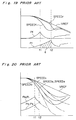
- solid lines indicate a case in which antiskid control for 2WD is performed for the motor vehicle under 2WD.
- locking symptom of the front wheel is detected and the brake fluid pressure Pf of the front wheel is reduced.
- locking symptom of the rear wheel is not detected until a time point t2 and thus, the brake fluid pressure Pr of the rear wheel is increased until the time point t2.
- antiskid control for 4WD is performed for the motor vehicle under 2WD
- the brake fluid pressure Pr of the rear wheel is also reduced as shown by the one-dot chain line and thus, loss of braking force is incurred by an amount corresponding to a hatched portion a. Therefore, in case antiskid control for 4WD is performed for the motor vehicle under 2WD, such a problem arises that especially in the case of a road surface having low coefficient ⁇ of friction, for example, a snow-covered road surface and a frozen road surface, braking distance increases greatly.
- each of the wheel speeds SPEED2 and SPEED3 is equal to ⁇ 0.5 x (SPEED0 + SPEED1) ⁇ and thus, the wheel speeds SPEED2 and SPEED3 of the rear wheels follow the wheel speeds SPEED0 and SPEED1 of the front wheels.
- an essential object of the present invention is to provide, with a view to eliminating the above mentioned drawbacks of prior art antiskid control device for a motor vehicle of part-time 4WD, an antiskid control device for a motor vehicle of part-time 4WD, which is capable of, even if a changeover means for effecting changeover between 2WD and 4WD fails, performing antiskid control for 2WD positively when the motor vehicle is under 2WD.
- the antiskid control device of Claim 1 is an antiskid control device for use in a motor vehicle which can be changed over to 2WD and 4WD by the changeover means and includes the drive mode judging means which detects from behaviors of the wheels that the actual drive mode of the motor vehicle is 2WD when the changeover means is set to 4WD. Therefore, in case the drive mode of the motor vehicle is 2WD, antiskid control for 2WD is performed positively.
- a longitudinal speed difference equal to a difference between an average front wheel speed and an average rear wheel speed is smoothed into a smoothed longitudinal speed difference by a smoothed longitudinal speed difference calculating means such that when this smoothed longitudinal speed difference falls out of a range between a predetermined upper threshold value and a predetermined lower threshold value, it is judged that the drive mode of the motor vehicle is 2WD. Therefore, also when wheel speeds oscillate, it is possible to positively detect that the actual drive mode of the motor vehicle is 2WD when the changeover means is set to 4WD.
- An antiskid control device of Claim 3 includes a first arithmetic means for calculating and outputting an arithmetic value subjected to addition and subtraction when the longitudinal speed difference is positive and negative, respectively such that when this arithmetic value falls out of a range between a predetermined upper threshold value and a predetermined lower threshold value, it is judged that the drive mode of the motor vehicle is 2WD.
- a predetermined upper threshold value a predetermined lower threshold value
- An antiskid control device of Claim 4 includes a first arithmetic means for calculating an arithmetic value subjected to addition and subtraction when the longitudinal speed difference is not less than a predetermined positive upper limit value and not more than a predetermined negative lower limit value, respectively such that this longitudinal speed difference falls out of a range between the upper threshold value and the lower threshold value, neither addition nor subtraction for the arithmetic value is performed. Since it is judged that the drive mode of the motor vehicle is 2WD if the arithmetic value falls out of a range between an upper threshold value and a lower threshold value, it is judged that the drive mode of the motor vehicle is 2WD. Therefore, it is possible to further positively detect that the drive mode of the motor vehicle is 2WD.
- An antiskid control device of Claim 5 includes a first arithmetic means for calculating and outputting an arithmetic value subjected to addition and subtraction when the smoothed longitudinal speed difference is positive and negative, respectively such that when this arithmetic value falls out of a range between an upper threshold value and a lower threshold value, it is judged that the actual drive mode of the motor vehicle is 2WD. Accordingly, it is possible to further positively detect that the drive mode of the motor vehicle is 2WD.
- An antiskid control device of Claim 6 includes a first arithmetic means for calculating and outputting an arithmetic value when the smoothed longitudinal speed difference is not less than a predetermined positive upper limit value and not more than a predetermined negative lower threshold value, respectively such that when this arithmetic value falls out of a range between an upper threshold value and a lower threshold value, it is judged that the actual drive mode of the motor vehicle is 2WD. Therefore, it is possible to further positively detect that the drive mode of the motor vehicle is 2WD.
- An antiskid control device of Claims 7 and 8 includes a second arithmetic means which inspects the arithmetic value at an interval of a predetermined number of control cycles so as to perform subtraction and addition for the arithmetic value when the arithmetic value is positive and negative, respectively. Accordingly, since neither subtraction nor addition for the arithmetic value is performed unnecessarily by temporary behaviors of the wheels, it is possible to prevent erroneous detection of 2WD.
- an antiskid control device of Claim 9 if the drive mode judging means detects that the drive mode of the motor vehicle is 2WD, antiskid control for 2WD is performed until antiskid control is finished. Therefore, antiskid control for 2WD is not changed over to antiskid control for 4WD during antiskid control.
- absolute values of the upper and lower threshold values are set large during a predetermined period from start of braking of the motor vehicle. Thus, it is possible to detect 2WD without undergoing influences of oscillations of the wheel speeds at the time of start of braking.
- the longitudinal speed difference is inclined to extend into a region of the lower threshold value at the time of 4WD.
- an antiskid control device of Claim 11 by setting an absolute value of the lower threshold value larger than that of the upper threshold value, it is possible to positively prevent erroneous detection of 2WD.
- the longitudinal speed difference is apt to extend into a region of the upper threshold value at the time of 4WD.
- an antiskid control device of Claim 12 by setting an absolute value of the upper threshold value larger than that of the lower threshold value, it is possible to positively prevent erroneous detection of 2WD.
- an antiskid control device of Claim 13 only when a vehicle body deceleration detected by a longitudinal acceleration sensor is not more than a preset value, 2WD is detected. Therefore, only on a road surface having low coefficient ⁇ of friction, for which changeover between antiskid control for 2WD and antiskid control for 4WD is quite necessary, changeover between antiskid control for 2WD and antiskid control for 4WD is performed.
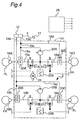
- a driving shaft 1 includes a front driving shaft 1a for front wheels and a rear driving shaft 1b for rear wheels.
- the front and rear driving shafts 1a and 1b are coupled with and uncoupled from each other by a central control mechanism 3.
- a front differential mechanism 5 is coupled with the front driving shaft 1a.
- axles 6a and 6b which are, respectively, coupled with front left and right wheels FL and FR are coupled with the front differential mechanism 5.
- a rear differential mechanism 7 is coupled with the rear driving shaft 1b.
- axles 8a and 8b which are, respectively, coupled with rear left and right wheels RL and RR are coupled with the rear differential mechanism 7.
- a changeover switch SW acting as a changeover means is provided for effecting changeover between 2WD and 4WD.
- the changeover switch SW is operated manually so as to change over drive modes of the motor vehicle.
- a drive signal output means DSO outputs to the central control mechanism 3 a drive signal DS commanding uncoupling or coupling between the front and rear driving shafts 1a and 1b.
- the drive signal output means DSO outputs to the central control mechanism 3 a low-level drive signal DS (2WD command) for uncoupling the front and rear driving shafts 1a and 1b from each other so as to set the motor vehicle to 2WD state.
- the drive signal output means DSO outputs to the central control mechanism 3 a high-level drive signal DS (4WD command) for coupling the front and rear driving shaft 1a and 1b with each other so as to set the motor vehicle to 4WD state.
- the drive signal output means DSO outputs this drive signal DS also to an electronic control unit 25 to be described later.
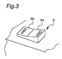
- a seesaw type switch 9 shown in Fig. 3 is provided as the changeover switch SW in the vicinity of a driver's seat.
- the drive signal output means DSO outputs the low-level drive signal DS (2WD command).
- the drive signal output means DSO outputs the high-level drive signal DS (4WD command).
- the changeover switch SW is not restricted to this seesaw type switch 9 but may also be formed by one of various manual switches such as a push switch, a slide switch, etc.
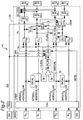
- a master cylinder 12 actuated by a brake pedal 11 and a fluid pressure adjusting means 14 are connected with each other by conduits 13a and 13b.
- One conduit 13a is connected, through the fluid pressure adjusting means 14, with a conduit 16a leading to a wheel brake 18A of the front left wheel FL and a conduit 16d leading to a wheel brake 18D of the rear right wheel RR.
- the other conduit 13b is connected, via the fluid pressure adjusting means 14, with a conduit 16b leading to a wheel brake 18B of the front right wheel FR and a conduit 16c leading to a wheel brake 18C of the rear left wheel RL.
- the fluid pressure adjusting means 14 is actuated by the drive signal DS from the electronic control unit 25 so as to adjust fluid pressure of the wheel brakes 18A, 18B, 18C and 18D of the front left and right wheels FL and FR and the rear left and right wheels RL and RR.
- the fluid pressure adjusting means 14 is of return flow type.
- the conduit 13a is connected with the conduits 16a and 16d in the fluid pressure adjusting means 14.
- a return flow path 19a branches off from the conduit 16a and then, is connected with a location of the conduit 16a disposed between a branch point of the return flow path 19a and the master cylinder 12.
- a return flow path 19d branches off from the conduit 16d and then, is connected with a location of the conduit 16d disposed between a branch point of the return flow path 19d and the master cylinder 12.
- Inlet valves 20A and 20D formed by flow control valves are, respectively, provided at the branch points of the return flow paths 19a and 19d.
- the flow return paths 19a and 19d are, respectively, connected with a first reservoir 22A through outlet valves 21A and 21D each formed by an ON/OFF type normally closed solenoid valve.
- Working fluid discharged from the wheel brakes 18A and 18D at the time of depressurization of antiskid control is stored in the first reservoir 22A.
- the working fluid is pumped up from the first reservoir 22A by a first pump 23A so as to be returned to the master cylinder 12.
- conduit 13b is also connected with the conduits 16b and 16c in the fluid pressure adjusting means 14 in the same manner as the conduit 13a.
- inlet valves 20B and 20C each formed by a flow control valve are provided at branch points of return flow paths 19b and 19c, respectively.
- Outlet valves 21B and 21C each formed by an ON/OFF type normally closed solenoid valve are provided in the course of the return paths 19b and 19c, respectively.
- a second reservoir 22B is provided so as to be connected, through a second pump 23B, with the master cylinder 12. Therefore, working fluid discharged from the wheel brakes 18B and 18C is stored in the second reservoir 22B and is pumped up from the second reservoir 22B by the second pump 23B so as to be returned to the master cylinder 12.
- the first and second pumps 23A and 23B are known plunger pumps driven by a driving motor 24. However, the first and second pumps 23A and 23B are not restricted to the plunger pumps but may also be formed by pumps of other types.
- closing and opening of the outlet valves 21A to 21D are controlled by pressure increase and reduction signals outputted from pressure increase and reduction setting means SOL0, SOL1, SOL2 and SOL3. If the outlet valves 21A to 21D are in closed state, working fluid is supplied from the master cylinder 12 to the wheel brakes 18A to 18D so as to increase brake fluid pressure. On the other hand, if the outlet valves 21A to 21D are opened, working fluid in the wheel brakes 18A to 18D is discharged into the reservoirs 22A and 22B so as to reduce brake fluid pressure.
- each of the inlet valves 20A to 20D may be formed by an ON/OFF type normally open solenoid valve. In this case, if the inlet valves are opened and the outlet valves are closed during antiskid control, brake fluid pressure is increased. On the contrary, if the inlet valves are closed and the outlet valves are opened, brake fluid pressure is reduced. Furthermore, if both the inlet valves and the outlet valves are closed, brake fluid pressure is held.
- the fluid pressure adjusting means 14 may be of volume increase type in which a piston is provided and braking volume is increased or reduced upon movement of the piston so as to reduce or increase brake fluid pressure.
- wheel speed sensors S0, S1, S2 and S3 outputs to the electronic control unit 25 pulse signals having frequencies proportional to rotational speeds of the front left and right wheels FL and FR and the rear left and right wheels RL and RR, respectively.
- the wheel speed sensors S0 to S3 are, respectively, secured to the axles 6a, 6b, 8a and 8b.
- each of the wheel speed sensors S0 to S3 includes a disk made of magnetic material and having a serrated outer periphery and a magnetic pickup disposed in the vicinity of this disk.
- a longitudinal acceleration sensor GS detects a longitudinal acceleration of the motor vehicle and outputs the longitudinal acceleration to the electronic control unit 25.
- a brake switch BSW outputs to the electronic control unit 25 a high-level brake signal BS indicating that the brake pedal 11 is being kicked.
- the brake switch BS outputs a low-level brake signal BS to the electronic control unit 25.
- the electronic control unit 25 is formed by a microcomputer and includes a wheel and vehicle body behavior calculating means CAL, a drive mode judging means DJDG, antiskid control decision means C0, C1, C2 and C3, first to fourth low-selection means SL1, SL2, SL3 and SL4, the pressure increase and reduction setting means SOL0, SOL1, SOL2 and SOL3, an antiskid control changeover means CSW and a control state judging means ALJDG.
- the wheel and vehicle body behavior calculating means CAL calculates wheel speeds SPEED0, SPEED1, SPEED2 and SPEED3 of the front left and right wheels FL and FR and the rear left and right wheels RL and RR on the basis of the pulse signals outputted by the wheel speed sensors S0 to S3 and outputs the calculated wheel speeds SPEED0 to SPEED3 to the antiskid control decision means C0, C1, C2 and C3, respectively.
- the wheel and vehicle body behavior calculating means CAL outputs the wheel speeds SPEED0 and SPEED1 of the front left and right wheels FL and FR to an average front wheel speed calculating means SfCAL to be described later and outputs the wheel speeds SPEED2 and SPEED3 of the rear left and right wheels RL and RR to an average rear wheel speed calculating means SrCAL to be described later.
- sign of the wheel acceleration and deceleration ⁇ d(SPEED i )/dt ⁇ is set to be positive for acceleration and negative for deceleration.
- the wheel and vehicle body behavior calculating means CAL calculates an estimated value of a vehicle body speed, i.e., an estimated vehicle body speed VREF from the wheel speeds SPEED0 to SPEED3 and outputs the estimated vehicle body speed VREF to the antiskid control decision means C0 to C3.
- This estimated vehicle body speed VREF is calculated by known procedures. For example, a maximum value of the wheel speeds SPEED0 to SPEED3 may be set as the estimated vehicle body speed VREF.
- the wheel and vehicle body behavior calculating means CAL calculates a vehicle body deceleration GCEL from an output of the longitudinal acceleration sensor GS and outputs the calculated vehicle body deceleration GCEL to a judgement means JDG of the drive mode judging means DJDG.
- sign of the vehicle body deceleration GCEL is set to be positive for deceleration and negative for acceleration.
- the average rear wheel speed calculating means SrCAL outputs this average rear wheel speed Sr to the longitudinal speed difference calculating means SBTCAL of the drive mode judging means DJDG.
- Sr (SPEED2 + SPEED3) / 2
- the drive mode judging means DJDG includes the longitudinal speed difference calculating means SBTCAL, a smoothed longitudinal speed difference calculating means FLTR and the judgement means JDG.
- the average front wheel speed Sf and the average rear wheel speed Sr are inputted to the longitudinal speed difference calculating means SBTCAL.
- the longitudinal speed difference calculating means SBTCAL calculates a longitudinal speed difference Vd which is a difference between the average front wheel speed Sf and the average rear wheel speed Sr.
- the longitudinal speed difference calculating means SBTCAL outputs this longitudinal speed difference Vd to the smoothed longitudinal speed difference calculating means FLTR.
- Vd Sf - Sr
- the smoothed longitudinal speed difference calculating means FLTR calculates a smoothed longitudinal speed difference Vdf through filtering of the longitudinal speed difference Vd and outputs this smoothed longitudinal speed difference Vdf to the judgement means JDG.
- the smoothed longitudinal speed difference Vdf is calculated by subjecting the longitudinal speed difference Vd to low-pass filtering as indicated by the following equation (4).
- Vdf Vdf ⁇ + (1/k) x (Vd - Vdf ⁇ )
- the smoothed longitudinal speed difference Vdf in the left member represents a smoothed longitudinal speed difference in this control cycle
- the underlined smoothed longitudinal speed difference Vdf in the right member represents a smoothed longitudinal speed difference in the preceding control cycle
- k denotes a filter constant larger than 1, i.e., k > 1.
- smoothing of the longitudinal speed difference Vd by the smoothed longitudinal speed difference calculating means FLTR is not restricted to low-pass filtering referred to above but may also be performed by any filtering capable of removing oscillatory component of the longitudinal speed difference Vd.
- the judgement means JDG judges that actual drive mode of the motor vehicle is 2WD and sets a judgement flag FLAG to "1" corresponding to 2WD.
- the judgement means JDG judges that actual drive mode of the motor vehicle may not be 2WD and sets the judgement flag FLAG to "0".
- This judgement flag FLAG is outputted to the antiskid control changeover means CSW.
- the brake signal BS is inputted from the brake switch BSW to the judgement means JDG.
- the judgement means JDG detects start of braking upon change of the brake signal from low level to high level and sets absolute values of the upper threshold value Vth1 and the lower threshold value Vth2 large during a predetermined period from start of braking.
- the judgement means JDG receives also the drive signal DS from the drive signal output means DSO.
- the judgement means JDG judges the drive modes of the motor vehicle.
- the judgment means JDG does not judge the drive modes of the motor vehicle.
- the judgement means JDG receives also an antiskid signal AL from the control state judging means ALJDG.
- this antiskid signal AL is at high level indicating that antiskid control is being performed
- the judgement means JDG judges the drive modes of the motor vehicle.
- the judgement means JDG does not judge the drive modes of the motor vehicle.
- the judgement means JDG receives the vehicle body deceleration GCEL from the wheel and vehicle body behavior calculating means CAL.
- the judgement means JDG judges the drive modes of the motor vehicle.
- the judgement means JDG does not judge the drive modes of the motor vehicle.
- the antiskid control decision means C0, C1, C2 and C3 detects locking symptom of the wheels FL, FR, RL and RR from the estimated vehicle body speed VREF, the wheel speeds SPEED0 to SPEED3 and the wheel acceleration and deceleration ⁇ d(SPEED i )/dt ⁇ , respectively.
- the antiskid control decision means C0, C1, C2 and C3 decide that there is locking symptom and output signals commanding pressure reduction of the wheel brakes 18A to 18D at pressure reduction duties corresponding to the estimated vehicle body speed VREF and the wheel speeds SPEED0 to SPEED3.
- the antiskid control decision means C0 to C3 decide that locking symptom has disappeared and output signals commanding pressure increase of the wheel brakes 18A to 18D at pressure increase duties corresponding to the estimated vehicle body speed VREF and the wheel speeds SPEED0 to SPEED3.
- the signal of the antiskid control decision means C0 for the front left wheel FL is outputted to the pressure increase and reduction setting means SOL0 and the second low-selection means SL2.
- the signal of the antiskid control decision means C1 for the front right wheel FR is outputted to the pressure increase and reduction setting means SOL1 and the third low-selection means SL3.
- the signals of the antiskid control decision means C2 and C3 for the rear left and right wheels RL and RR are inputted to the first low-selection means SL1.
- the first to fourth low-selection means SL1 to SL4 output signals each corresponding to one in compared two of the wheels FL, FR, RL and RR having more manifest locking symptom than the other in the two.
- the signals of the antiskid control decision means C2 and C3 for the rear left and right wheels RL and RR are inputted to the first low-selection means SL1, while an output of the first low-selection means SL1 is applied to a first input A1 of the antiskid control changeover means CSW and the second and third low-selection means SL2 and SL3.
- the signal of the antiskid control decision means C0 for the front left wheel FL and the signal from the first low-selection means SL1 are inputted to the second low-selection means SL2, while an output of the second low-selection means SL2 is applied to the fourth low-selection means SL4.
- the signal of the antiskid control decision means C1 and the signal from the first low-selection means SL1 are inputted to the third low-selection means SL3, while an output of the third low-selection means SL3 is applied to the fourth low-selection means SL4.
- the signals from the second and third low-selection means SL2 and SL3 are inputted to the fourth low-selection means SL4, while an output of the fourth low-selection means SL4 is applied to a second input A2 of the antiskid control changeover means CSW.
- the antiskid control changeover means CSW includes the first and second inputs A1 and A2 and an output B.
- the first input A1 is connected to the first low-selection means SL1 and the second input A2 is connected to the fourth low-selection means SL4. Meanwhile, the output B is connected to the pressure increase and reduction setting means SOL2 and SOL3.
- the antiskid control changeover means CSW connects the first input A1 and the output B with each other irrespective of value of the judgement flag FLAG from the drive mode judging means DJDG.
- the antiskid control changeover means CSW connects the second input A2 and the output B with each other if the judgement flag FLAG from the drive mode judging means DJDG is "0" indicative of 4WD. Meanwhile, if the judgement flag FLAG from the drive mode judging means DJDG is "1" indicative of 2WD, the antiskid control changeover means CSW connects the first input A1 and the output B with each other.
- Antiskid control for 4WD is performed as follows. Namely, in case the second input A2 and the output B of the antiskid control changeover means CSW are connected to each other, the signals from the antiskid control decision means C0 and C1 for the front left and right wheels FL and FR are directly inputted to the pressure increase and reduction setting means SOL0 and SOL1, respectively. One of the signals of the antiskid control decision means C0 to C3, which has the most manifest locking symptom in these signals, is inputted to the pressure increase and reduction setting means SOL2 and SOL3 for the rear left and right wheels RL and RR.
- antiskid control for 2WD is performed as follows. Namely, in case the first input A1 and the output B of the antiskid control changeover means CSW are connected to each other, the signals from the antiskid control decision means C0 and C1 for the front left and right wheels FL and FR are directly inputted to the pressure increase and reduction setting means SOL0 and SOL1, respectively.
- the pressure increase and reduction setting means SOL0 to SOL3 set opening and closing time periods of the outlet valves 21A to 21D of the actuators ACT0 to ACT3 on the basis of the signals inputted to the pressure increase and reduction setting means SOL0 to SOL3 and output, as the pressure increase and reduction signals, the set opening and closing time periods to the actuators ACT0 to ACT3.
- the control state judging means ALJDG judges that antiskid control is being performed for a corresponding one of the wheels FL, FR, RL and RR and outputs to the drive mode judging means DJDG the high-level antiskid signal AL indicating that antiskid control is being performed.
- the control state judging means ALJDG outputs to the drive mode judging means DJDG the low-level antiskid signal AL indicating that antiskid control is not being performed.
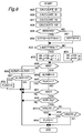
- step #1 when a power source of the motor vehicle has been turned on, processings of steps #1 to #4 of Fig. 5 are repeated at a predetermined period (control cycle).
- step #1 the signals from the sensors and the switches are read.
- processings shown in Fig. 6 are performed.
- the wheel and vehicle body behavior calculating means CAL reads the pulse signals outputted by the wheel speed sensors S0 to S3.
- step #12 the wheel and vehicle body behavior calculating means CAL reads the output of the longitudinal acceleration sensor GS.
- the judgement means JDG and the antiskid control changeover means CSW read the drive signal DS indicative of setting of the changeover switch SW.
- step #14 the judgement means JDG reads the brake signal BS from the brake switch BSW.
- the wheel and vehicle body behavior calculating means CAL calculates behaviors of the wheels and behaviors of the vehicle body.
- processings shown in Fig. 7 are performed.
- the wheel and vehicle body behavior calculating means CAL calculates the wheel speeds SPEED0 to SPEED3 from the outputs of the wheel speed sensors S0 to S3 and outputs the wheel speeds SPEED0 to SPEED3 to the antiskid control decision means C0 to C3.
- the wheel and vehicle body behavior calculating means CAL outputs the wheel speeds SPEED0 and SPEED1 to the average front wheel speed calculating means SfCAL and the wheel speeds SPEED2 and SPEED3 to the average rear wheel speed calculating means SrCAL. Then, at step #18, the wheel and vehicle body behavior calculating means CAL calculates the wheel accelerations and decelerations ⁇ d(SPEED0)/dt ⁇ to ⁇ d(SPEED3)/dt ⁇ from the wheel speeds SPEED0 to SPEED3, respectively and outputs the wheel accelerations and decelerations ⁇ d(SPEED0)/dt ⁇ to ⁇ d(SPEED3)/dt ⁇ to the antiskid control decision means C0 to C3, respectively.
- the wheel and vehicle body behavior calculating means CAL calculates the estimated vehicle body speed VREF from the wheel speeds SPEED0 to SPEED3 and outputs the estimated vehicle body speed VREF to the antiskid control decision means C0 to C3.
- the wheel and vehicle body behavior calculating means CAL calculates the vehicle body deceleration GCEL from the output of the longitudinal acceleration sensor GS and outputs the vehicle body deceleration GCEL to the judgement means JDG.
- the drive mode judging means DJDG judges whether or not actual drive mode of the motor vehicle body is 2WD.
- processings shown in Fig. 8 are performed. Initially, at step #25 of Fig. 8, the average front wheel speed calculating means SfCAL calculates the average front wheel speed Sf from the equation (1) referred to earlier and outputs the average front wheel speed Sf to the longitudinal speed difference calculating means SBTCAL. At step #26, the average rear wheel speed calculating means SrCAL calculates the average rear wheel speed SrCAL from the earlier mentioned equation (2) and outputs the average rear wheel speed Sr to the longitudinal speed difference calculating means SBTCAL.
- the longitudinal speed difference calculating means SBTCAL calculates the longitudinal speed difference Vd from the above mentioned equation (3) and outputs the longitudinal speed difference Vd to the smoothed longitudinal speed difference calculating means FLTR.
- the smoothed longitudinal speed difference calculating means FLTR calculates the smoothed longitudinal speed difference Vdf by subjecting the longitudinal speed difference Vd to low-pass filtering.
- the judgement means JDG judges whether or not the motor vehicle is being braked. In case the motor vehicle is being braked, namely, the brake signal BS is at high level, the program flow proceeds to step #30. In case the motor vehicle is not being braked, namely, the brake signal BS is at low level, the program flow proceeds to step #31.
- step #30 "1" is added to count of a braking timer STPTM.
- step #31 count of the braking timer STPTM is cleared to "0". If it is found at step #32 that count of the braking timer STPTM satisfies the relation ( ⁇ ⁇ STPTM ⁇ 1), it is judged that it is within a predetermined period from start of braking and thus, the program flow proceeds to step #33. On the other hand, if count of the braking timer STPTM falls out of the above mentioned range, it is judged that braking is not being performed or the predetermined period has elapsed from start of braking and thus, the program flow proceeds to step #34.
- the upper threshold value Vth1 for the smoothed longitudinal speed difference Vdf is set to a sum of a standard value Vth10 and ⁇ 1, while the lower threshold value Vth2 is set to a value obtained by subtracting ⁇ 2 from a standard value Vth20.
- ⁇ 1 and ⁇ 2 are positive predetermined values.
- the upper and lower threshold values Vth1 and Vth2 are set to the standard values Vth10 and Vth20, respectively without addition or subtraction and then, the program flow proceeds to step #35.
- the judgement means JDG judges whether or not antiskid control is being performed. If antiskid control is not being performed, namely, the antiskid signal AL is at low level, the program flow proceeds to step #36 without forming a judgement on the drive modes. On the contrary, if antiskid control is being performed, namely, the antiskid signal AL is at high level, the program flow proceeds to step #39.
- step #37 After "1" has been subtracted from count of an antiskid timer ALTMR at step #36, the program flow proceeds to step #37. If it is found at step #37 that count of the antiskid timer ALTMR is "0", it is judged that antiskid control has not yet been performed or a sufficiently long period has elapsed from the last antiskid control. Then, at step #38, the judgement flag FLAG is set to "0". On the other hand, at step #39, count of the antiskid timer ALTMR is set to a sufficiently large predetermined value k. At step #40, the judgement flag FLAG is inspected.
- step #40 If the judgement flag FLAG is "1" at step #40, it is detected that not only antiskid control is being performed but actual drive mode of the motor vehicle is 2WD although the changeover switch SW has already been set to 4WD. Therefore, during antiskid control, a judgement on the drive modes is not formed such that the judgement flag FLAG is held at "1". On the other hand, when the judgement flag FLAG is "0" at step #40, the program flow proceeds to step #41.
- step #41 it is inspected from the drive signal DS whether the changeover switch SW is set to 2WD or 4WD. In case the changeover switch SW is set to 2WD, namely, the drive signal DS is at low level, a judgement on the drive modes is not formed. In case the changeover switch SW is set to 4WD, namely, the drive signal DS is at high level, the program flow proceeds to step #42.
- the judgement means JDG inspects whether or not the vehicle body deceleration GCEL from the wheel and vehicle body behavior calculating means CAL is equal to a positive predetermined value g or less.
- the smoothed longitudinal speed difference Vdf is compared with the upper threshold value Vth1. If the smoothed longitudinal speed difference Vdf is not less than the upper threshold value Vth1, it is judged that since difference between the average front wheel speed Vf and the average rear wheel speed Vr is sufficiently large, actual drive mode of the motor vehicle is 2WD and thus, the judgement flag FLAG is set to "1" at step #44. On the other hand, if the smoothed longitudinal speed difference Vdf is less than the upper threshold value Vth1, the program flow proceeds to step #45. At step #45, the smoothed longitudinal speed difference Vdf is compared with the lower threshold value Vth2.
- the judgement flag FLAG is set to "1" at step #44.
- step #4 of Fig. 5 the pressure increase and reduction signals are set and outputted.
- processings shown in Fig. 9 are performed.
- the antiskid control changeover means CSW inspects the drive signal DS. If the drive signal DS is at high level, namely, the changeover switch SW is set to 4WD, the program flow proceeds to step #52. On the other hand, if the drive signal DS is at low level, namely, the changeover switch SW is set to 2WD, the program flow proceeds to step #53. At step #52, the judgement flag FLAG is inspected.
- step #53 If the judgement flag FLAG is "1”, the changeover switch SW is set to 4WD but actual drive mode of the motor vehicle is judged 2WD, so that the program flow proceeds to step #53. Meanwhile, if the judgement flag FLAG is "0”, the changeover switch SW is set to 4WD and actual drive mode of the motor vehicle is also 4WD, so that the program flow proceeds to step #54.
- antiskid control for 2WD is performed as follows. Namely, signals from the antiskid control decision means C0 and C1 are inputted to the pressure increase and reduction setting means SOL0 and SOL1 for the front left and right wheels FL and FR, respectively. Meanwhile, one of signals from the antiskid control decision means C2 and C3, which has more manifest locking symptom than the other of these signals, is inputted to the pressure increase and reduction setting means SOL2 and SOL3 for the rear left and right wheels RL and RR.
- the pressure increase and reduction setting means SOL0 to SOL3 set the pressure increase and reduction signals on the basis of the inputted signals and output the pressure increase and reduction signals to the actuators ACT0 to ACT3.
- antiskid control for 4WD is performed as follows. Namely, signals from the antiskid control decision means C0 and C1 are inputted to the pressure increase and reduction setting means SOL0 and SOL1 for the front left and right wheels FL and FR, respectively. One of signals from the antiskid control decision means C0 to C3 for the front left and right wheels FL and FR and the rear left and right wheels RL and RR, which has the most manifest locking symptom in these signals, is inputted to the pressure increase and reduction setting means SOL2 and SOL3.
- the pressure increase and reduction setting means SOL0 to SOL3 set the pressure increase and reduction signals on the basis of the inputted signals and output the pressure increase and reduction signals to the actuators ACT0 to ACT3.
- Fig. 10 shows one example of control of the antiskid control device K1.
- the changeover switch SW is set to 4WD and the drive signal DS outputted by the drive signal output means DSO is at high level.
- the brake pedal 11 is actuated so as to start braking of the motor vehicle.
- absolute values of the upper threshold value Vth1 and the lower threshold value Vth2 are set large. Since behaviors of the wheels are unstable at an initial stage of braking, it is possible to positively prevent erroneous detection of 2WD by setting the upper and lower threshold values Vth1 and Vth2 as described above.
- the drive mode judging means DJDG starts judging the drive modes.
- the smoothed longitudinal speed difference Vdf exceeds the lower threshold value Vth2 at a time point t4
- the drive mode judging means DJDG sets the judgement flag FLAG to "1" by judging that the changeover switch SW is set to 4WD but actual drive mode of the motor vehicle is 2WD.
- This judgement flag FLAG is inputted to the antiskid control changeover means CSW as described above.
- the first input A1 and the output B of the antiskid control changeover means CSW are connected to each other and thus, antiskid control for 2WD is performed until antiskid control is finished.
- antiskid control for 2WD is performed until antiskid control is finished. Therefore, since changeover from control for 2WD to control for 4WD is not performed during antiskid control, behaviors of the motor vehicle can be stabilized.
- the drive modes of the motor vehicle are judged only when the vehicle body deceleration GCEL detected by the longitudinal acceleration sensor GS during antiskid control is not more than the set predetermined value, detection of 2WD is performed only for a road surface having low coefficient ⁇ of friction, which requires changeover between antiskid control for 2WD and antiskid control for 4WD.
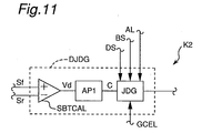
- Fig. 11 shows a drive mode judging means DJDG of an antiskid control device K2 according to a second embodiment of the present invention.
- the drive mode judging means DJDG of the antiskid control device K2 includes a longitudinal speed difference calculating means SBTCAL, an arithmetic means AP1 and a judgement means JDG. From the equation (3) referred to earlier in the same manner as the first embodiment, the longitudinal speed difference calculating means SBTCAL calculates the longitudinal speed difference Vd which is a difference between the average front wheel speed Sf and the average rear wheel speed Sr and outputs the longitudinal speed difference Vd to the arithmetic means AP1.
- the arithmetic means AP1 When the longitudinal speed difference Vd is positive, the arithmetic means AP1 adds "1" to an arithmetic value C. On the contrary, when the longitudinal speed difference Vd is negative, the arithmetic means AP1 subtracts "1" from the arithmetic value C. Then, the arithmetic means AP1 outputs this arithmetic value C to the judgement means JDG. If this arithmetic value C falls within a range between a positive upper threshold value Cth1 and a negative lower threshold value Cth2, the judgement means JDG sets the judgement flag FLAG to "0". Meanwhile, if the arithmetic value C falls out of the range, the judgement means JDG sets the judgement flag FLAG to "1" corresponding to 2WD.
- the judgement means JDG outputs this judgement flag FLAG to the antiskid control changeover means CSW. Meanwhile, the judgement means JDG judges start of braking from the high-level brake signal BS and sets absolute values of the upper and lower threshold values Cth1 and Cth2 large during a predetermined period from start of braking. Since other constructions of the antiskid control device K2 are identical with those of the antiskid control device K1, the description is abbreviated for the sake of brevity.
- step #3 of Fig. 5 operation of the antiskid control device K2 is the same as that of the antiskid control device K1.
- step #3 of the antiskid control device K2 processings shown in Figs. 11 and 12 are performed. Steps #25 to #31 in Fig. 12 are identical with those of Fig. 8 for the first embodiment except that calculation of the smoothed longitudinal speed difference Vdf (step #28 of Fig. 8) is not performed in Fig. 12.
- step #56 If it is found at step #56 that count of the braking timer STPTM satisfies the relation ( ⁇ ⁇ STPTM ⁇ 1), it is judged that it is within a predetermined period from start of braking and thus, the program flow proceeds to step #57 at which the upper threshold value Cth1 of the arithmetic value C is set to a sum of a standard value Cth1 and a positive predetermined value ⁇ 1 and the lower threshold value Cth2 of the arithmetic value C is set to a value obtained by subtracting a positive predetermined value ⁇ 2 from a standard value Cth20.
- step #58 for setting the upper and lower threshold values Cth1 and Cth2 to the standard values Cth10 and Cth20, respectively without addition or subtraction and then, the program flow proceeds to step #35.
- step #38-1 at which in case antiskid control has not yet been performed or a sufficiently long period has elapsed from the last antiskid control, the arithmetic value C is cleared to "0"
- processings from step #35 to step #42 in Fig. 13 are identical with those of Fig. 8 for the first embodiment.
- step #35 in case antiskid control is not being performed (step #35), the judgement flag FLAG has been set to "1" indicative of 2WD (step #40), the changeover switch SW is set to 2WD (step #41) and the vehicle body deceleration GCEL is larger than the predetermined value g (step #42), a judgement on the drive modes of the motor vehicle is not formed.
- step #60 it is inspected whether or not the longitudinal speed difference Vd is larger than "0". If the longitudinal speed difference Vd is larger than "0", namely, the longitudinal speed difference Vd is positive, the program flow proceeds to step #61. On the other hand, if the longitudinal speed difference Vd is not larger than "0", the program flow proceeds to step #62. At step #61, "1" is added to the arithmetic value C. Meanwhile, at step #62, it is inspected whether or not the longitudinal speed difference Vd is smaller than "0". In case the longitudinal speed difference Vd is smaller than "0", namely, the longitudinal speed difference Vd is negative, "1" is subtracted from the arithmetic value C at step #63.
- the arithmetic value C is compared with the upper threshold value Cth1. In case the arithmetic value C is not less than the upper threshold value Cth1, it is judged that since a state that the average front wheel speed Vf is larger than the average rear wheel speed Vr has lasted for a sufficiently long period, the changeover switch SW is set to 4WD but actual drive mode of the motor vehicle is 2WD, so that the judgement flag FLAG is set to 1 at step #65. On the other hand, if it is found at step #64 that the arithmetic value C is smaller than the upper threshold value Cth1, the program flow proceeds to step #66. At step #66, the arithmetic value C is compared with the lower threshold value Cth2.
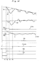
- Fig. 14 shows one example of control of the antiskid control device K2.
- the changeover switch SW is set to 4WD and the drive signal DS outputted by the drive signal output means DSO is at high level.
- the brake pedal 11 is actuated so as to start braking of the motor vehicle.
- absolute values of the upper and lower threshold values Vth1 and Vth2 of the arithmetic value C are set large. Therefore, at an initial stage of braking, the drive modes of the motor vehicle are judged as being 2WD only when a state that a difference between the average front wheel speed Vf and the average rear wheel speed Vr is large has lasted for a period longer than the predetermined period counted from start of braking.
- Antiskid control is started at a time point t2 and the arithmetic value C drops below the lower threshold value Cth2 at a time point t4.
- the drive mode judging means DJDG judges that the changeover switch SW is set to 4WD but actual drive mode of the motor vehicle is 2WD and sets the judgement flag FLAG to "1".
- the first input A1 is connected to the output B in the antiskid control changeover means CSW such that antiskid control for 2WD is performed.
- Fig. 15 shows a drive mode judging means DJDG of an antiskid control device K3 according to a third embodiment of the present invention.
- the drive mode judging means DJDG of the antiskid control device K3 includes a longitudinal speed difference calculating means SBTCAL, a first arithmetic means AP1, a second arithmetic means AP2 and a judgement means JDG.
- the longitudinal speed difference Vd is larger than a positive upper limit ⁇
- the first arithmetic means AP1 adds "1" to the arithmetic value C.
- the longitudinal speed difference Vd is smaller than a negative lower limit - ⁇
- the first arithmetic means AP1 subtracts "1" from the arithmetic value C.
- a range of ( ⁇ ⁇ C ⁇ - ⁇ ) is set as an insensitive zone such that addition or subtraction of the arithmetic value C is not performed in case the longitudinal speed difference Vd falls within this insensitive range.
- the second arithmetic means AP2 inspects the arithmetic value C at an interval of a predetermined number N (N ⁇ 2) of the control cycles so as to subtract "1" from and add "1" to the arithmetic value C when the arithmetic value C is positive and negative, respectively. Since other constructions of the antiskid control device K3 are identical with those of the antiskid control device K2, the description is abbreviated for the sake of brevity.
- step #71 If it is found at step #71 that the longitudinal speed difference Vd is larger than the positive upper limit ⁇ , "1" is added to the arithmetic value C at step #72. Meanwhile, if the longitudinal speed difference Vd is not more than the upper limit ⁇ , the program flow proceeds to step #73. If it is found at step #73 that the longitudinal speed difference Vd is smaller than the negative lower limit - ⁇ , "1" is subtracted from the arithmetic value C.
- step #76 determines whether or not the arithmetic value C is positive. If the arithmetic value C is positive at step #76, "1" is subtracted from the arithmetic value C at step #77. On the other hand, if the arithmetic value C is not positive at step #76, it is inspected at step #78 whether or not the arithmetic value C is negative. If the arithmetic value C is negative at step #78, "1" is added to the arithmetic value C at step #79.
- the range of ( ⁇ ⁇ C ⁇ - ⁇ ) is set as an insensitive zone such that addition or subtraction of the arithmetic value C is not performed in case the longitudinal speed difference Vd falls within this insensitive range as described above. Accordingly, also when oscillations of the wheel speeds are large, erroneous detection of 2WD can be prevented.
- the second arithmetic means AP2 performs addition and subtraction for the arithmetic value C oppositely to the first arithmetic means AP1 in accordance with whether the arithmetic value C is positive or negative, unnecessary addition or subtraction for the arithmetic value C due to temporary behaviors of the wheels can be prevented and thus, it is possible to judge 2WD more accurately.
- Fig. 17 shows a drive mode judging means DJDG of an antiskid control device K4 according to a fourth embodiment of the present invention.
- the smoothed longitudinal speed difference calculating means FLTR similar to that of the antiskid control device K1 is provided between the longitudinal speed difference calculating means SBTCAL and the arithmetic means AP1 of the antiskid control device K2 such that addition and subtraction for the arithmetic value C are performed on the basis of whether the smoothed longitudinal speed difference Vdf is positive or negative.
- Fig. 18 shows a drive mode judging means DJDG of an antiskid control device K5 according to a fifth embodiment of the present invention.
- the smoothed longitudinal speed difference calculating means FLTR is provided between the longitudinal speed difference calculating means SBTCAL and the first arithmetic means AP1 of the antiskid control device K3. Accordingly, also in the fifth embodiment, since addition and subtraction for the arithmetic value C are performed on the basis of whether the smoothed longitudinal speed difference Vdf in the same manner as the fourth embodiment, oscillatory components of the wheel speeds are removed further positively and thus, it is possible to judge more accurately that the drive mode of the motor vehicle is 2WD.
- the present invention is not restricted to the above mentioned embodiments but can be modified variously.
- the drive mode judging means DJDG may set absolute values of the upper threshold values Vth1 and Cth1 larger than those of the lower threshold values Vth2 and Cth2.
- the longitudinal speed difference Vd is inclined to greatly extend into a region of the upper threshold value Vth1 and this state is apt to last for a long time, thereby resulting in addition for the arithmetic value C.
- the drive mode judging means DJDG may set absolute values of the lower threshold values Vth2 and Cth2 larger than those of the upper threshold values Vth1 and Cth1.
- the longitudinal speed difference Vd is inclined to greatly extend into a region of the lower threshold value Vth2 and this state is apt to last for a long time, thus resulting in subtraction for the arithmetic value C. Therefore, by setting the lower threshold values Vth2 and Cth2 as described above, the drive modes of the motor vehicle can be judged further accurately.
- the rear left and right wheels RL and RR may be controlled on the basis of signals from one of the rear left and right wheels RL and RR, which has more manifest locking symptom than the other of the rear left and right wheels RL and RR.
- the antiskid control device of Claim 1 is an antiskid control device which can be changed over to 2WD and 4WD and includes the drive mode judging means which detects from behaviors of the wheels that the actual drive mode of the motor vehicle is 2WD when the changeover means is set to 4WD.
- this drive mode judging means detects that the actual drive mode of the motor vehicle is 2WD
- antiskid control for 2WD is performed. Therefore, also in case malfunctions of the changeover switch, etc. happen, antiskid control for 2WD can be performed positively when the drive mode of the motor vehicle is 2WD.
- this antiskid control device is capable of preventing extension of braking distance caused when antiskid control for 4WD is performed at the time of 2WD especially on a road surface having low coefficient of friction.
- the longitudinal speed difference equal to the difference between the average front wheel speed and the average rear wheel speed is smoothed into the smoothed longitudinal speed difference by the smoothed longitudinal speed difference calculating means such that when the smoothed longitudinal speed difference falls out of the range between the predetermined upper threshold value and the predetermined lower threshold value, it is judged that the drive mode of the motor vehicle is 2WD. Therefore, also in case the wheel speeds oscillate, it is possible to positively detect that the actual drive mode of the motor vehicle is 2WD when the changeover means is set to 4WD.
- the antiskid control device of Claim 3 includes the first arithmetic means for calculating and outputting the arithmetic value subjected to addition and subtraction when the longitudinal speed difference is positive and negative, respectively such that when this arithmetic value falls out of the range between the predetermined upper threshold value and the predetermined lower threshold value, it is judged that the drive mode of the motor vehicle is 2WD. Therefore, also when the wheel speeds oscillate, it is possible to prevent erroneous detection of 2WD.
- the antiskid control device of Claim 4 includes the first arithmetic means for calculating the arithmetic value subjected to addition and subtraction when the longitudinal speed difference is not less than the predetermined positive upper limit value and is not more than the predetermined negative lower limit value, respectively such that when this arithmetic value falls out of the range between the predetermined upper threshold value and the predetermined lower threshold value, it is judged that the drive mode of the motor vehicle is 2WD. Accordingly, also when the wheel speeds oscillate, it is possible to prevent erroneous detection of 2WD.
- the antiskid control device of Claim 5 includes the first arithmetic means for calculating the arithmetic value subjected to addition and subtraction when the smoothed longitudinal speed difference is positive and negative, respectively such that when the arithmetic value falls out of the range between the upper threshold value and the lower threshold value, it is judged that the actual drive mode of the motor vehicle is 2WD. Therefore, it is possible to further positively prevent erroneous detection of 2WD due to oscillations of the wheel speeds.
- the antiskid control device of Claim 6 includes the first arithmetic means for calculating the arithmetic value subjected to addition and subtraction when the smoothed longitudinal speed difference is not less than the predetermined positive upper limit value and not more than the predetermined negative lower limit value, respectively, such that when the arithmetic value falls out of the range between the upper threshold value and the lower threshold value, it is judged that the actual drive mode of the motor vehicle is 2WD.
- the first arithmetic means for calculating the arithmetic value subjected to addition and subtraction when the smoothed longitudinal speed difference is not less than the predetermined positive upper limit value and not more than the predetermined negative lower limit value, respectively, such that when the arithmetic value falls out of the range between the upper threshold value and the lower threshold value, it is judged that the actual drive mode of the motor vehicle is 2WD.
- the antiskid control device of Claim 7 includes the second arithmetic means which inspects the arithmetic value at an interval of a predetermined number of control cycles so as to perform subtraction and addition for the arithmetic value when the arithmetic value is positive and negative, respectively. Therefore, it is possible to prevent erroneous detection of 2WD due to unnecessary addition or subtraction for the arithmetic value caused by temporary behaviors of the wheels.
- the antiskid control device of Claim 8 if the drive mode judging means detects that the drive mode of the motor vehicle is 2WD, antiskid control for 2WD is performed until antiskid control is finished. Accordingly, since antiskid control for 2WD is not changed over to antiskid control for 4WD during antiskid control, it is possible to secure stability of the motor vehicle.
- absolute value of the lower threshold value is set larger than that of the upper threshold value in the motor vehicle of front wheel drive at the time of 2WD.
- the longitudinal speed difference is inclined to extend into a region of the lower threshold value at the time of 4WD.
- absolute value of the upper threshold value is set larger than that of the lower threshold value in the motor vehicle of rear wheel drive at the time of 2WD.
- longitudinal speed difference is apt to extend into a region of the upper threshold value at the time of 4WD. Therefore, by setting the upper and lower threshold values as described above, it is possible to prevent erroneous detection of 2WD further positively.
Landscapes
- Engineering & Computer Science (AREA)
- Transportation (AREA)
- Mechanical Engineering (AREA)
- Physics & Mathematics (AREA)
- Fluid Mechanics (AREA)
- Microelectronics & Electronic Packaging (AREA)
- Chemical & Material Sciences (AREA)
- Combustion & Propulsion (AREA)
- Regulating Braking Force (AREA)
Applications Claiming Priority (3)
| Application Number | Priority Date | Filing Date | Title |
|---|---|---|---|
| JP10412994 | 1994-05-18 | ||
| JP104129/94 | 1994-05-18 | ||
| JP6104129A JPH07309221A (ja) | 1994-05-18 | 1994-05-18 | アンチスキッド制御装置 |
Publications (3)
| Publication Number | Publication Date |
|---|---|
| EP0683078A2 true EP0683078A2 (de) | 1995-11-22 |
| EP0683078A3 EP0683078A3 (de) | 1997-11-12 |
| EP0683078B1 EP0683078B1 (de) | 2001-11-21 |
Family
ID=14372510
Family Applications (1)
| Application Number | Title | Priority Date | Filing Date |
|---|---|---|---|
| EP95106720A Expired - Lifetime EP0683078B1 (de) | 1994-05-18 | 1995-05-04 | Antischlupf-Steuergerät |
Country Status (5)
| Country | Link |
|---|---|
| US (1) | US5740042A (de) |
| EP (1) | EP0683078B1 (de) |
| JP (1) | JPH07309221A (de) |
| KR (1) | KR0160578B1 (de) |
| DE (1) | DE69523981T2 (de) |
Cited By (2)
| Publication number | Priority date | Publication date | Assignee | Title |
|---|---|---|---|---|
| EP0764569A3 (de) * | 1995-09-21 | 1998-07-15 | Robert Bosch Gmbh | ABS-Steuerung für vierradgetriebenes Fahrzeug mit Achsschwingungen |
| EP0774390A3 (de) * | 1995-11-20 | 1999-07-14 | Toyota Jidosha Kabushiki Kaisha | Steuergerät für ein Antiblockier-Bremssystem |
Families Citing this family (9)
| Publication number | Priority date | Publication date | Assignee | Title |
|---|---|---|---|---|
| US6246945B1 (en) * | 1996-08-10 | 2001-06-12 | Daimlerchrysler Ag | Process and system for controlling the longitudinal dynamics of a motor vehicle |
| WO2008147364A1 (en) * | 2007-06-01 | 2008-12-04 | Deere & Company | Momentary activation of mechanical front wheel drive |
| US8655567B2 (en) * | 2009-11-09 | 2014-02-18 | Toyota Jidosha Kabushiki Kaisha | Brake control device |
| US10166865B2 (en) | 2010-10-18 | 2019-01-01 | Ford Global Technologies, Llc | Automatic control of driveline states |
| US9076272B2 (en) * | 2013-05-28 | 2015-07-07 | Infineon Technologies Ag | Wheel speed sensor and interface systems and methods |
| US9434251B2 (en) * | 2014-07-17 | 2016-09-06 | Honda Motor Co., Ltd. | All-wheel drive failsafe action axle torque calculation method |
| JP2016084110A (ja) * | 2014-10-29 | 2016-05-19 | トヨタ自動車株式会社 | 車両の制御装置 |
| DE112017000006T5 (de) * | 2016-02-05 | 2017-10-26 | Warn Industries, Inc. | Steuersystem und -Verfahren für ein Fahrzeug mit Vierradantrieb |
| CN117698746B (zh) * | 2024-01-17 | 2025-04-18 | 广州汽车集团股份有限公司 | 车辆坡度计算方法及装置、电子设备、存储介质 |
Family Cites Families (11)
| Publication number | Priority date | Publication date | Assignee | Title |
|---|---|---|---|---|
| JPS62120276A (ja) * | 1985-11-20 | 1987-06-01 | Nissan Motor Co Ltd | 4輪駆動・4輪操舵車両 |
| JP2519894B2 (ja) * | 1986-04-10 | 1996-07-31 | 曙ブレーキ工業株式会社 | アンチスキツド制御方法 |
| JPH01114535A (ja) * | 1987-10-28 | 1989-05-08 | Mazda Motor Corp | 4輪駆動車 |
| JP2575452B2 (ja) * | 1988-03-31 | 1997-01-22 | 日産自動車株式会社 | 四輪駆動車のアンチスキッド制御装置 |
| US5184695A (en) * | 1988-06-10 | 1993-02-09 | Honda Giken Kogyo Kabushiki | Method for controlling a change-over between two and four-wheel drive modes for a vehicle |
| JPH01311939A (ja) * | 1988-06-10 | 1989-12-15 | Aisin Seiki Co Ltd | 全輪駆動車両のアンチスキツドブレーキ装置 |
| JP2707806B2 (ja) * | 1990-06-15 | 1998-02-04 | 三菱自動車工業株式会社 | 4輪駆動用アンチスキッドブレーキ制御方法 |
| JPH04110264A (ja) * | 1990-08-30 | 1992-04-10 | Sumitomo Electric Ind Ltd | 学習補正機能を備えたアンチロック制御装置 |
| JP2998327B2 (ja) * | 1991-08-10 | 2000-01-11 | アイシン精機株式会社 | アンチスキッド制御装置 |
| US5407024A (en) * | 1992-06-24 | 1995-04-18 | Borg-Warner Automotive, Inc. | On demand vehicle drive system |
| US5411110A (en) * | 1993-03-09 | 1995-05-02 | New Venture Gear, Inc. | Power transfer system for a four-wheel drive vehicle |
-
1994
- 1994-05-18 JP JP6104129A patent/JPH07309221A/ja active Pending
-
1995
- 1995-04-17 US US08/423,636 patent/US5740042A/en not_active Expired - Fee Related
- 1995-05-04 EP EP95106720A patent/EP0683078B1/de not_active Expired - Lifetime
- 1995-05-04 DE DE69523981T patent/DE69523981T2/de not_active Expired - Fee Related
- 1995-05-18 KR KR1019950012396A patent/KR0160578B1/ko not_active Expired - Fee Related
Cited By (2)
| Publication number | Priority date | Publication date | Assignee | Title |
|---|---|---|---|---|
| EP0764569A3 (de) * | 1995-09-21 | 1998-07-15 | Robert Bosch Gmbh | ABS-Steuerung für vierradgetriebenes Fahrzeug mit Achsschwingungen |
| EP0774390A3 (de) * | 1995-11-20 | 1999-07-14 | Toyota Jidosha Kabushiki Kaisha | Steuergerät für ein Antiblockier-Bremssystem |
Also Published As
| Publication number | Publication date |
|---|---|
| US5740042A (en) | 1998-04-14 |
| DE69523981T2 (de) | 2002-07-18 |
| DE69523981D1 (de) | 2002-01-03 |
| KR950031732A (ko) | 1995-12-20 |
| JPH07309221A (ja) | 1995-11-28 |
| KR0160578B1 (ko) | 1998-12-01 |
| EP0683078A3 (de) | 1997-11-12 |
| EP0683078B1 (de) | 2001-11-21 |
Similar Documents
| Publication | Publication Date | Title |
|---|---|---|
| US5558415A (en) | Method of enhancing the reliablity in operation of a brake system with electronic control of the brake force distribution | |
| EP0305950B1 (de) | Bremssystem mit einem Gerät zum Steuern des in einem Speicher zu sammelnden Drucks zum Bremsen eines Kraftfahrzeugs | |
| US5669677A (en) | ABS and/or ASC control system for motor vehicles | |
| EP0655376B1 (de) | Gerät zur Fehlererkennung eines Längsbeschleunigungsmesser | |
| KR100221684B1 (ko) | 차량의 선회 제어장치 | |
| EP0683078A2 (de) | Antischlupf-Steuergerät | |
| GB2303186A (en) | Controlling the brake system of a vehicle | |
| US6009366A (en) | Process for monitoring a braking system with antilock system and electronic braking power distribution | |
| JP3781429B2 (ja) | アンチロックコントロール式ブレーキ装置のための回路装置 | |
| US6089682A (en) | Antilock brake control system for vehicle | |
| JPH01145253A (ja) | 4輪駆動車用アンチロツク制御装置 | |
| US5071200A (en) | Abs pressure reapply logic | |
| EP1702822A1 (de) | Kraftfahrzeug-Bremssteuergerät und zugehöriges Steuerungsverfahren | |
| JP4381481B2 (ja) | カーブでのabsの制御状態を改善する方法 | |
| EP0774390B1 (de) | Steuergerät für ein Antiblockier-Bremssystem | |
| JP3277664B2 (ja) | アンチスキッド制御装置 | |
| JPH0986377A (ja) | 液圧制御装置 | |
| JPH08282460A (ja) | 車輌の挙動制御装置 | |
| US4953092A (en) | Anti-skid control device | |
| EP0291978B1 (de) | Antirutschvorrichtung | |
| US6341828B1 (en) | Brake control system and method | |
| JP3456012B2 (ja) | アンチスキッド制御装置 | |
| JP3309599B2 (ja) | アンチスキッド制御装置 | |
| JP3768546B2 (ja) | 走行状態判定装置 | |
| EP3715200B1 (de) | Steuerungsvorrichtung für fahrzeugbremse |
Legal Events
| Date | Code | Title | Description |
|---|---|---|---|
| PUAI | Public reference made under article 153(3) epc to a published international application that has entered the european phase |
Free format text: ORIGINAL CODE: 0009012 |
|
| 17P | Request for examination filed |
Effective date: 19950705 |
|
| AK | Designated contracting states |
Kind code of ref document: A2 Designated state(s): DE FR GB |
|
| RIN1 | Information on inventor provided before grant (corrected) |
Inventor name: FUJIOKA, HIDEAKI, C/O ITAMI WORKS OF |
|
| PUAL | Search report despatched |
Free format text: ORIGINAL CODE: 0009013 |
|
| AK | Designated contracting states |
Kind code of ref document: A3 Designated state(s): DE FR GB |
|
| 17Q | First examination report despatched |
Effective date: 20000406 |
|
| GRAG | Despatch of communication of intention to grant |
Free format text: ORIGINAL CODE: EPIDOS AGRA |
|
| GRAG | Despatch of communication of intention to grant |
Free format text: ORIGINAL CODE: EPIDOS AGRA |
|
| GRAH | Despatch of communication of intention to grant a patent |
Free format text: ORIGINAL CODE: EPIDOS IGRA |
|
| GRAH | Despatch of communication of intention to grant a patent |
Free format text: ORIGINAL CODE: EPIDOS IGRA |
|
| GRAA | (expected) grant |
Free format text: ORIGINAL CODE: 0009210 |
|
| AK | Designated contracting states |
Kind code of ref document: B1 Designated state(s): DE FR GB |
|
| REG | Reference to a national code |
Ref country code: GB Ref legal event code: IF02 |
|
| REF | Corresponds to: |
Ref document number: 69523981 Country of ref document: DE Date of ref document: 20020103 |
|
| ET | Fr: translation filed | ||
| PLBE | No opposition filed within time limit |
Free format text: ORIGINAL CODE: 0009261 |
|
| STAA | Information on the status of an ep patent application or granted ep patent |
Free format text: STATUS: NO OPPOSITION FILED WITHIN TIME LIMIT |
|
| 26N | No opposition filed | ||
| PGFP | Annual fee paid to national office [announced via postgrant information from national office to epo] |
Ref country code: GB Payment date: 20040428 Year of fee payment: 10 |
|
| PGFP | Annual fee paid to national office [announced via postgrant information from national office to epo] |
Ref country code: FR Payment date: 20040510 Year of fee payment: 10 |
|
| PGFP | Annual fee paid to national office [announced via postgrant information from national office to epo] |
Ref country code: DE Payment date: 20040513 Year of fee payment: 10 |
|
| PG25 | Lapsed in a contracting state [announced via postgrant information from national office to epo] |
Ref country code: GB Free format text: LAPSE BECAUSE OF NON-PAYMENT OF DUE FEES Effective date: 20050504 |
|
| PG25 | Lapsed in a contracting state [announced via postgrant information from national office to epo] |
Ref country code: DE Free format text: LAPSE BECAUSE OF NON-PAYMENT OF DUE FEES Effective date: 20051201 |
|
| GBPC | Gb: european patent ceased through non-payment of renewal fee |
Effective date: 20050504 |
|
| PG25 | Lapsed in a contracting state [announced via postgrant information from national office to epo] |
Ref country code: FR Free format text: LAPSE BECAUSE OF NON-PAYMENT OF DUE FEES Effective date: 20060131 |
|
| REG | Reference to a national code |
Ref country code: FR Ref legal event code: ST Effective date: 20060131 |