EP0683079A1 - Véhicule de sauvetage pour un téléphérique - Google Patents
Véhicule de sauvetage pour un téléphérique Download PDFInfo
- Publication number
- EP0683079A1 EP0683079A1 EP95810322A EP95810322A EP0683079A1 EP 0683079 A1 EP0683079 A1 EP 0683079A1 EP 95810322 A EP95810322 A EP 95810322A EP 95810322 A EP95810322 A EP 95810322A EP 0683079 A1 EP0683079 A1 EP 0683079A1
- Authority
- EP
- European Patent Office
- Prior art keywords
- basket
- salvage
- cable
- recovery
- rope
- Prior art date
- Legal status (The legal status is an assumption and is not a legal conclusion. Google has not performed a legal analysis and makes no representation as to the accuracy of the status listed.)
- Ceased
Links
- 238000011084 recovery Methods 0.000 title claims abstract description 58
- 238000010276 construction Methods 0.000 claims abstract description 5
- 239000000725 suspension Substances 0.000 abstract description 23
- 238000007689 inspection Methods 0.000 description 1
Images


Classifications
-
- B—PERFORMING OPERATIONS; TRANSPORTING
- B61—RAILWAYS
- B61B—RAILWAY SYSTEMS; EQUIPMENT THEREFOR NOT OTHERWISE PROVIDED FOR
- B61B3/00—Elevated railway systems with suspended vehicles
-
- B—PERFORMING OPERATIONS; TRANSPORTING
- B61—RAILWAYS
- B61B—RAILWAY SYSTEMS; EQUIPMENT THEREFOR NOT OTHERWISE PROVIDED FOR
- B61B12/00—Component parts, details or accessories not provided for in groups B61B7/00 - B61B11/00
- B61B12/005—Rescue devices for passengers
Definitions
- the invention relates, on the one hand, to a rescue vehicle for the transport vehicles of a cable car, with a carriage conveyed on at least one support rope and at least one traction rope, with a salvage basket and with a hanger which is pivotally mounted on the drive and on which the salvage basket hangs below, the salvage basket opposite Drive with a traction device from a driving position to a salvage position can be lowered or raised.
- the invention relates to a rescue vehicle for the transport vehicles of a cable car, with a hanger which is pivotally mounted on at least one carrying pull rope and on which a rescue basket hangs at the bottom, the rescue basket being moved from a driving position to a pulling device with respect to its reception on the carrying pull rope Salvage position can be lowered or raised.
- cable cars are to be equipped with an emergency vehicle if an area is difficult to walk on, on which the passengers cannot be roped down. Thanks to the high level of operational safety achieved by cable cars today, the recovery vehicles are practically almost unused facilities, since such emergencies generally do not occur. However, the rescue vehicles must always be available for use in accordance with the regulations for emergencies and an annual inspection of the vehicles is provided, in which their operational readiness and functionality is determined and approved.
- the hanger In a known recovery vehicle with the features mentioned above, which is provided for a cable car with two suspension cables for the transport vehicle, on which the recovery vehicle is also conveyed, the hanger consists of several square tubes articulated at their ends.
- the upper square tube hangs on Undercarriage, the salvage cage is firmly attached to the lower square tube and can be brought to the required height in several stages with a cable pulling device to the transport vehicle and locked on the square tube.
- the plurality of joints are designed as locking joints which snap into place between the square tubes.
- the well-known recovery vehicle is parked in the mountain station. Since the extended hanger is too long with its salvage basket reaching below the platform, the entire salvage vehicle with the drive is removed from the carrying cables and stored in a storage space at the mountain station.
- the salvage basket is removed from the hanger, the hanger can be folded up in the locking joints and the square tubes fastened to each other next to each other. Removing the recovery vehicle from the suspension cables or putting it back on the suspension cables until it is ready for operation takes a long time and is also a very dangerous matter.
- the task is to be solved to park the entire salvage vehicle, i.e. drive with suspension including salvage basket and pulling device, in a very confined space and to keep it fully functional and ready for use.
- the hanger consists of several traction means, preferably wire ropes, on which the traction means of the traction device acts.
- the multiple wire ropes of the suspension alternatively chains can be provided, form a (statically determined) truss, the tension rods of which consist of traction means; the clamping points or deflections of the traction means are the joints of the framework.
- the half-timbered construction gives the hanger according to the invention the necessary stability against pendulum movements around the three axes of the spatial coordinate system.
- fixed fixings of the suspension cables can also be provided.
- the rescue vehicle according to the invention is therefore resistant to disturbances during driving when driving over supports and very stable against wind influences, since it has only one, but necessary, joint in which pendulum movements are possible, through which the hanger, including the salvage basket, adapts to the different inclinations on the conveyor line. Because of the flexible half-timbered construction, the drive, hangers and salvage basket of the salvage vehicle according to the invention can be contracted while slackening the traction means of the hangers.
- a traction device is provided, as is known for example from DE 36 04 365 C2, which acts on the taut traction means of the hanger.
- the lane can consist of a support cable or two support cables and have a separate pull cable, or two of them.
- the pull rope for the recovery vehicle can belong to a winch or be guided all the way round.
- the lane of the recovery vehicle can also be the lane of the transport vehicle, for example in the case of a cable car; however, it is also possible to set up a separate lane only for the recovery vehicle between the two lanes for the transport vehicles, for example in the case of a cable car, in which case the recovery vehicle can also convey into the valley station.
- the support rope can also be a pull rope; in this case, the suspension cable has a rotating cable drive and in turn a separate lane is set up only for the recovery vehicle between the two lanes for the transport vehicles; two carrying cables can also be provided.
- the invention has a four-point suspension, consisting of four equally long wire ropes, between an upper and a lower crossbar stretched, each attack on an upper corner of the salvage basket and from there to the cable pulling device.
- This inventive design of the truss gives the hanger together with the salvage basket high stability against tipping about one of the two horizontal axes with asymmetrical loading.
- a particularly stable hanger with additional struts results in the invention if the four wire cables are each clamped at one end at the corner point of the lower crossmember, deflected at a corner point of the upper crossbar and attack at the opposite corner point of the salvage cage.
- the four wire cables of the hanger are guided on the load hooks of the cable pulling device arranged in the center of the recovery cage, which acts with its pulling rope on the lower crossbar of the hanger.
- the four wire ropes in the invention are unwound or wound up by a rope drum which is accommodated in the bottom of the recovery cage and accordingly has multiple grooves and on which they engage in the same direction of rotation, and the pulling rope of the rope pulling device engages in a further groove of the rope drum in the opposite direction a.
- the salvage basket is therefore free of hanging ropes. In the salvage position, the cable drum is locked on the ground.
- stops are provided on the recovery vehicle to limit the total stroke when lifting or lowering the recovery basket on the cable drum, which cooperate with a stop on the bottom of the recovery basket and permit approximately one full rotation of the cable drum.
- two bolts in pin holes on the bottom of the salvage basket can be repositioned to limit the partial stroke when lifting or lowering the salvage basket, strike the spokes of the cable drum and enable gradual lowering or lifting of the salvage basket.
- the rescue vehicle which is conveyed in the driving position to the mountain station, can be placed under another cable pulling device Slacken the slack in the sling in the direction of the drive from the driving position into a parking position.
- the second cable pull device always remains in the top station, is hung there for parking the recovery vehicle on the upper crossbar of the suspension and attacks with four pull cables at the corners on the bottom of the recovery basket; it remains in engagement in the parked recovery vehicle.
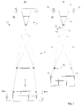
- a recovery vehicle is designated by 1 in total. It consists of a drive 2, a salvage basket 3 and a hanger 4 between drive 2 and salvage basket 3; the salvage basket 3 hangs on the bottom of four wire ropes of the hanger 4.
- the drive 2 shown is intended for a lane consisting of two suspension cables. 1b it has a rectangular frame 2 1. At the four corners of the frame 2 1 22 wheels are attached, which roll on the two cables of a cable car. In the case of a single cable car, at least two running wheels are provided on the running gear for stable guidance on the standing cable. With the frame 2 1 a triangular suspension 2 3 is firmly connected in the side view, at the lower corner of which a hinge 2 3 1 is arranged for pivotally accommodating the hanger 4 on the drive 2.
- the hanger 4 consists of an upper 431 and a lower cross member 42 and four equally long wire ropes 41. Both trusses 42 and 431 have rectangular frames.
- the upper cross member 431 is extended with a vertical rod 432 upwards and at the end of its extension in the joint 231 on the drive 2nd articulated. Between the two trusses 42 and 43 and the salvage basket 3, the four wire ropes 41 are stretched:
- Each wire rope 41 is attached at one end to a corner point of the rectangular frame of the lower cross member 42, is deflected at the diagonally opposite corner point of the upper cross member 431 and led to the associated corner point of the lower cross member 42. There it can be deflected and attack the associated upper corner point of the recovery cage 3 and in turn deflected by means of a roller 3 1 arranged there to be continued to a cable pulling device, not shown in FIG.
- the lower guide rollers 32 steer the suspension cables 41 from the vertical to the horizontal and guide them to a cable drum 6 housed in the bottom of the recovery basket 3, on which they are wound in the same direction.
- Fig.2c the leadership of a single wire rope 411 on the rope drum 6 is shown wound, which corresponds to the driving position of the recovery vehicle 1 according to Fig.2a.
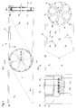
- the four suspension cables 411 to 414 are each attached at one end via a cable clamp 45 and a cable lock 44 to a corner of the lower cross member 42 and at the other end comprise the cable drum shaft 63 with a cable loop 46.
- a cable pulling device For lowering or lifting the recovery vehicle 1, a cable pulling device , generally designated 5, is provided according to FIG .
- the pulling device 5 1 is attached to one side of the recovery basket 3, as can be seen from FIG. 3 a, and engages with its pulling rope 5 2 in the opposite direction to the four suspension cables 4 11 to 4 1 on the cable drum 6.
- the cable routing of a total of five traction ropes, these are the four suspension ropes 411 to 414 and the traction rope 52 of the cable pulling device 5, on the cable drum 6 can be seen from the detail identified in Fig.3b with IIIc from Fig.3c.
- the cable drum 6 is shown removed from its storage 36 on a cross member 34 of the bottom frame 33.
- the cable ring 6 1 of the cable drum 6 is connected via spokes 6 2 to the receptacle for the cable drum shaft 6 3.
- On the lower bearing plate 64 two stops 641 and 642 are formed, which cooperate with a corresponding stop 35 on the floor frame 33 and between the upper stop 641 and the lower stop 642 allow approximately a full rotation of the cable drum 6.
- four bolt holes 371 to 374 are arranged on the cross member 34 of the base frame 33, which cooperate with the spokes 62 of the cable drum 6 to limit the partial stroke when lowering or lifting the recovery vehicle 1 via two insertable bolts 71 and 72.
- the total stroke limitation and the partial stroke limitation when lowering or lifting the recovery vehicle 1 is explained in detail with reference to FIG. 4:
- Fig.4a The total stroke limitation is shown in Fig.4a.
- the salvage cage 3 is at the top in the driving position F, and the cable drum 6 is turned to the bottom stop 642 of the cable drum 6 at the bottom stop 35 to the right; in Fig.4a II the upper stop 641 strikes after almost a complete left turn of the cable drum 6 at the bottom stop 35, the recovery basket 3 is located below in the recovery position B.
- Fig.4b shows the partial stroke limits in individual positions I to VIII.
- the two bolts 71 and 72 can be repositioned in the four bolt holes 371 to 374 on the floor frame 33 and allow a gradual lowering or lifting of the recovery basket 3 by means of the cable 5 from the driving - F to salvage position B:
- Fig.4b I corresponds to Fig.4a I.
- the cable 5 is the unwinding of the salvage basket 3 by about 30 ° rotation angle the cable drum 6 possible until the two bolts 7 1 and 7 2 as shown in FIG. 4b II strike the next spoke 62 in the direction of rotation.
- Bolt 72 secures during the change.
- Fig.4b IV bolt 72 is plugged into hole 372 and bolt 71 secures during the plugging. Then a lowering by a further 30 ° angle of rotation of the cable drum 6 is possible until the two bolts 7 1 and 7 2 as shown in FIG. 4b V strike the spoke 6 2 following in the direction of rotation again.
- Fig.4b VI bolt 71 is inserted into hole 373, bolt 72 secures during the change; thereafter can be changed according to Fig.4b VII bolt 72 in hole 374, while bolt 71 secures, according to Fig.4b VIII a further lowering by about 30 ° angle of rotation of the cable drum 6 is possible until the next spoke 62 on the two bolts 71 , 72 strikes.
- the recovery vehicle 1 is brought from its driving position F shown in FIG. 5a (corresponds to FIG. 1b), in which it extends from the mountain station and is returned to it, into a parking position P according to FIG. 5c which it is parked in the mountain station.
- a second cable pulling device 8 is installed, which engages one end with four pulling ropes 822 at the corners at the bottom of the salvage basket 3 and the other end is hung with another pulling rope 821 on the upper cross member 43 of the hanger 4.
- the salvage vehicle 1 to be garaged is essentially unloaded by means of the second cable 8 by an operator, slackening the wire cables 4 1 of the hanger 4, until it has reached the parking position P shown in FIG.
- 5 c in which it contracts in the vertical direction in a confined space is; the second cable pulling device 8 remains in the parking position P, in the lowered driving position F it is removed and remains at the top station.
- 5b is an intermediate position shown, in which the lower cross member 42 of the hanger 4 comes into contact with the salvage basket 3.
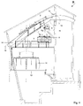
- the cable car is a pendulum cable car with two lanes, which are formed by two supporting cables 13 each.
- the top station is designated B, the transport vehicle stopping at the top station B is designated 11; the other transport vehicle is at the valley station.
- the passengers get on and off on a shifting platform 12 that serves both lanes.
- the two suspension ropes 13 of the cable car rest on a rope saddle 14 and at the same time serve as suspension ropes 13 for the recovery vehicle 1.
- 15 is a deflection wheel for the revolving pull rope of the transport vehicle 11.
- the salvage vehicle 1 is parked in front of a platform 16 in the parking position P shown in FIG. 5c, together with the engaged second cable pulling device 8, on the cable saddle 14.
- a salvage winch 9 is arranged in the ridge of the mountain station B and attacks with its pull rope on the joint 2 3 between the drive 2 and the hanger 4.
- a third cable pulling device 10 is provided, the load hook of which is hooked on one end to the masonry of the mountain station B and the other end engages with its pulling rope on the frame of the drive 2 and provides a slack pulling rope on the recovery winch 9.
- the third cable apparatus 10 can be handled from the platform 16.
- the complete recovery vehicle 1, parked essentially unnoticed, is always ready for use.
Landscapes
- Engineering & Computer Science (AREA)
- Transportation (AREA)
- Mechanical Engineering (AREA)
- Business, Economics & Management (AREA)
- Emergency Management (AREA)
- Emergency Lowering Means (AREA)
Applications Claiming Priority (2)
| Application Number | Priority Date | Filing Date | Title |
|---|---|---|---|
| CH153994 | 1994-05-18 | ||
| CH1539/94 | 1994-05-18 |
Publications (1)
| Publication Number | Publication Date |
|---|---|
| EP0683079A1 true EP0683079A1 (fr) | 1995-11-22 |
Family
ID=4212787
Family Applications (1)
| Application Number | Title | Priority Date | Filing Date |
|---|---|---|---|
| EP95810322A Ceased EP0683079A1 (fr) | 1994-05-18 | 1995-05-15 | Véhicule de sauvetage pour un téléphérique |
Country Status (4)
| Country | Link |
|---|---|
| EP (1) | EP0683079A1 (fr) |
| JP (1) | JPH07315212A (fr) |
| KR (1) | KR950031546A (fr) |
| CA (1) | CA2149483A1 (fr) |
Cited By (3)
| Publication number | Priority date | Publication date | Assignee | Title |
|---|---|---|---|---|
| EP1149749A1 (fr) * | 2000-04-28 | 2001-10-31 | High Technology Investments B.V. | Cabine de sauvetage et téléphérique de secours |
| WO2009040141A1 (fr) * | 2007-09-28 | 2009-04-02 | Rolic Invest Sarl | Système de transport à câble comprenant un véhicule de secours et procédé de fonctionnement |
| WO2018122790A1 (fr) * | 2016-12-29 | 2018-07-05 | Scotech Gmbh | Nacelle de maintenance et procédé de maintenance d'un téléphérique |
Families Citing this family (3)
| Publication number | Priority date | Publication date | Assignee | Title |
|---|---|---|---|---|
| JP5394098B2 (ja) * | 2009-02-26 | 2014-01-22 | 日本ケーブル株式会社 | 普通索道の救助装置 |
| CN107139939A (zh) * | 2016-11-18 | 2017-09-08 | 河北师范大学 | 一种城市道路应急运输系统 |
| IT201800006234A1 (it) * | 2018-06-12 | 2019-12-12 | Impianto di trasporto a fune |
Citations (5)
| Publication number | Priority date | Publication date | Assignee | Title |
|---|---|---|---|---|
| DE2541097A1 (de) * | 1975-09-15 | 1977-03-17 | Siemens Ag | Anordnung zum bergen von fahrgaesten aus einer kabine einer haengebahn |
| DE3526612A1 (de) * | 1985-07-25 | 1987-02-05 | Trefilarbed Drahtwerk | Brueckenseilinspektionsgeraet |
| DE3604365C2 (fr) | 1985-02-16 | 1987-05-27 | Willy Huenibach Ch Habegger | |
| EP0399413A1 (fr) * | 1989-05-23 | 1990-11-28 | Von Roll Seilbahnen AG | Installation de téléphérique avec chemin de secours |
| DE9312431U1 (de) * | 1993-08-17 | 1993-10-07 | Huneke, Otto, 32816 Schieder-Schwalenberg | Fahrbare Arbeitsbühne |
-
1995
- 1995-05-15 EP EP95810322A patent/EP0683079A1/fr not_active Ceased
- 1995-05-16 CA CA002149483A patent/CA2149483A1/fr not_active Abandoned
- 1995-05-17 KR KR1019950012266A patent/KR950031546A/ko not_active Withdrawn
- 1995-05-18 JP JP7120141A patent/JPH07315212A/ja active Pending
Patent Citations (5)
| Publication number | Priority date | Publication date | Assignee | Title |
|---|---|---|---|---|
| DE2541097A1 (de) * | 1975-09-15 | 1977-03-17 | Siemens Ag | Anordnung zum bergen von fahrgaesten aus einer kabine einer haengebahn |
| DE3604365C2 (fr) | 1985-02-16 | 1987-05-27 | Willy Huenibach Ch Habegger | |
| DE3526612A1 (de) * | 1985-07-25 | 1987-02-05 | Trefilarbed Drahtwerk | Brueckenseilinspektionsgeraet |
| EP0399413A1 (fr) * | 1989-05-23 | 1990-11-28 | Von Roll Seilbahnen AG | Installation de téléphérique avec chemin de secours |
| DE9312431U1 (de) * | 1993-08-17 | 1993-10-07 | Huneke, Otto, 32816 Schieder-Schwalenberg | Fahrbare Arbeitsbühne |
Cited By (4)
| Publication number | Priority date | Publication date | Assignee | Title |
|---|---|---|---|---|
| EP1149749A1 (fr) * | 2000-04-28 | 2001-10-31 | High Technology Investments B.V. | Cabine de sauvetage et téléphérique de secours |
| WO2009040141A1 (fr) * | 2007-09-28 | 2009-04-02 | Rolic Invest Sarl | Système de transport à câble comprenant un véhicule de secours et procédé de fonctionnement |
| WO2018122790A1 (fr) * | 2016-12-29 | 2018-07-05 | Scotech Gmbh | Nacelle de maintenance et procédé de maintenance d'un téléphérique |
| EP4005899A1 (fr) | 2016-12-29 | 2022-06-01 | SwissReviGondola AG | Procédé d'entretien d'un téléphérique |
Also Published As
| Publication number | Publication date |
|---|---|
| CA2149483A1 (fr) | 1995-11-19 |
| KR950031546A (ko) | 1995-12-18 |
| JPH07315212A (ja) | 1995-12-05 |
Similar Documents
| Publication | Publication Date | Title |
|---|---|---|
| EP3691985A1 (fr) | Procédé pour construire un système d'ascenseur présentant une hauteur de levage utile croissante | |
| DE202010008730U1 (de) | Transporteinrichtung für Druckplatten | |
| EP4172096A1 (fr) | Procédé pour construire un système d'ascenseur, et système d'ascenseur apte à mettre en oeuvre le procédé | |
| EP3212560B1 (fr) | Appareil élévateur à portique pour conteneurs iso | |
| EP0683079A1 (fr) | Véhicule de sauvetage pour un téléphérique | |
| DE3911868C2 (fr) | ||
| DE3508035C2 (fr) | ||
| DE3625876A1 (de) | Auf einem fahrzeug fahrbarer lastenaufzug mit gleisartigem teleskopausleger | |
| DE10254680B4 (de) | Portalhubwagen | |
| DE102016117287B4 (de) | Hebe-Vorrichtung für eine Transportplattform | |
| DE3733622C2 (fr) | ||
| DE3229186C2 (de) | An einem im wesentlichen senkrecht stehenden Gegenstand verfahrbares Gerät mit einem Transportgutträger | |
| DE2306358C3 (de) | Fahrzeug, insbesondere Lkw, für den Transport von Stahlbetonraumzellen, insbesondere Fertiggaragen | |
| EP3562726B1 (fr) | Nacelle de maintenance et procédé de maintenance d'un téléphérique | |
| DE4217109C2 (de) | Automatische Autoparkanlage | |
| DE10322827A1 (de) | Fahrzeug zum Transport von Gütern und Vorrichtung zur Sicherung von Ladung | |
| DE102010056322A1 (de) | Verfahren zum Be- oder Entladen von Transportgut sowie Vorrichtung zur Durchführung des Verfahrens sowie ein für die Vorrichtung nutzbarer Lastgutträger | |
| WO2009092364A2 (fr) | Dispositif et procédé de transport d'une charge entre une surface de représentation et une surface inférieure s'étendant sous celle-ci | |
| DE2635387C2 (de) | Kran | |
| DE2213287C3 (de) | Laufkatze mit Aufhängung des Lastaufnahmemittels zur Minderung des Lastpendeins | |
| DD287919A5 (de) | Verfahrbare auswechselvorrichtung fuer girlandentragrollenstationen | |
| DE3419706A1 (de) | Personenbefoerderungsvorrichtung | |
| DE102011122251A1 (de) | Lager-, Transport- und Hubeinrichtung für Kettenzüge | |
| DE3046285A1 (de) | Verladevorrichtung fuer lasten, insbesondere fuer geschosse | |
| DE2406251A1 (de) | Verfahren zum spannen und loesen von zusaetzlichen seilabschnitten eines zugseiles an einem hubwerk und vorrichtung zur durchfuehrung des verfahrens |
Legal Events
| Date | Code | Title | Description |
|---|---|---|---|
| PUAI | Public reference made under article 153(3) epc to a published international application that has entered the european phase |
Free format text: ORIGINAL CODE: 0009012 |
|
| AK | Designated contracting states |
Kind code of ref document: A1 Designated state(s): AT CH DE ES FR IT LI |
|
| 17P | Request for examination filed |
Effective date: 19951222 |
|
| 17Q | First examination report despatched |
Effective date: 19970617 |
|
| GRAG | Despatch of communication of intention to grant |
Free format text: ORIGINAL CODE: EPIDOS AGRA |
|
| STAA | Information on the status of an ep patent application or granted ep patent |
Free format text: STATUS: THE APPLICATION HAS BEEN REFUSED |
|
| 18R | Application refused |
Effective date: 19981018 |