EP4005899A1 - Procédé d'entretien d'un téléphérique - Google Patents
Procédé d'entretien d'un téléphérique Download PDFInfo
- Publication number
- EP4005899A1 EP4005899A1 EP22152686.6A EP22152686A EP4005899A1 EP 4005899 A1 EP4005899 A1 EP 4005899A1 EP 22152686 A EP22152686 A EP 22152686A EP 4005899 A1 EP4005899 A1 EP 4005899A1
- Authority
- EP
- European Patent Office
- Prior art keywords
- maintenance
- axle
- cable
- main
- sheave assembly
- Prior art date
- Legal status (The legal status is an assumption and is not a legal conclusion. Google has not performed a legal analysis and makes no representation as to the accuracy of the status listed.)
- Granted
Links
Images


Classifications
-
- B—PERFORMING OPERATIONS; TRANSPORTING
- B61—RAILWAYS
- B61B—RAILWAY SYSTEMS; EQUIPMENT THEREFOR NOT OTHERWISE PROVIDED FOR
- B61B12/00—Component parts, details or accessories not provided for in groups B61B7/00 - B61B11/00
-
- B—PERFORMING OPERATIONS; TRANSPORTING
- B61—RAILWAYS
- B61B—RAILWAY SYSTEMS; EQUIPMENT THEREFOR NOT OTHERWISE PROVIDED FOR
- B61B12/00—Component parts, details or accessories not provided for in groups B61B7/00 - B61B11/00
- B61B12/02—Suspension of the load; Guiding means, e.g. wheels; Attaching traction cables
- B61B12/028—Cabin or seat suspension means
-
- B—PERFORMING OPERATIONS; TRANSPORTING
- B61—RAILWAYS
- B61B—RAILWAY SYSTEMS; EQUIPMENT THEREFOR NOT OTHERWISE PROVIDED FOR
- B61B12/00—Component parts, details or accessories not provided for in groups B61B7/00 - B61B11/00
- B61B12/002—Cabins; Ski-lift seats
Definitions
- the invention relates to a maintenance cage for cable cars, a cable car and a method for maintaining a cable car.
- Cable cars transport cabins, chairs or other transport containers suspended on a rope between two locations.
- the cable is preferably circumferential.
- the cable in particular the hoisting cable, is carried on sheave assemblies supported by support structures.
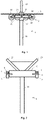
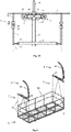
- Figures 1 and 2 show an example of a section of such a ropeway with a rope 3, a support structure 1 and a sheave assembly 2.
- the support structure 1 is designed here as a support pillar with a support shaft 11 and with a cross brace 12, also known as a yoke.
- the support shaft 11 and/or the cross brace 12 can also be replaced by other support structures, such as a building or a rock.
- the cross brace 12 preferably protrudes on two sides, so that a sheave assembly 2 can be mounted on each extremity of the cross brace 12, on which the cable 3 is moved in different directions.
- Support structures 1 often also have a lifting yoke 13 to which certain parts of the cable car, e.g. the cable 3, can be attached.
- the sheave assembly 2 is an assembly that has a plurality of sheaves 21 arranged one behind the other for guiding and securing the cable 3 .
- Sheave assemblies 2 carry the weight of a rope 3 and its hangers (upholder), press down a rope 3 (downholder) or combine these functions (changing holder).
- Figures 1 and 2 show an example of a hold-up device, which is only shown in detail in 1 shown while 2 the role batteries 2 shown only schematically as a square.
- the sheave assembly 2 generally has a battery structure and rope sheaves or sheaves 21 , the sheaves 21 being rotatably mounted in the battery structure, so that the rope 3 is guided on the sheaves 21 of the sheave assembly 2 .
- the battery structure is usually rotatable about a main axis 4 by means of a horizontal axis, which is perpendicular to the cable direction, mounted at one or both ends of the cross member 12.
- the battery structure itself has a main seesaw 24 and a plurality of seesaws 25 rotatably mounted on seesaw axles 23 (preferably having the same axial direction as the main axle 4) in the main seesaw 24.
- the rockers 25 support the individual rollers 21 (or other lower rockers) on corresponding roller axles 22.
- the lowest level of the rocker preferably has two rollers 21.
- the roller battery preferably has at least four rollers 21 .
- the sheave assembly 2 typically weighs more than 500 kg, often more than 1 or 2 tons, making it impossible for one person on site to move and maintain the sheave assembly.
- the maintenance of such a set of rollers 2 includes removing all pivots, cleaning and testing them and reinstalling the pivots. To do this, the sheave assembly 2 must be removed from the support pillar 1 using a crane or helicopter in order to carry out this maintenance, and then reassembled on this. This also requires that the roller battery 2 is accessible from above, for which the cable 3 must be removed from the rollers 21 of the roller battery 2 and moved inwards as a rule. This requires several hours of preparation for each pillar, in addition to the high cost of transporting the sheave assembly.
- EP2301819A2 , WO2015/003196 , EP2502799 show various maintenance baskets for the maintenance of a cable car, in particular EP2301819A2 and WO2015/003196 disclose a method of maintaining a reel assembly.
- EP0683079A1 and JPH02104374 show cable car vehicles for personal rescue.
- this goal is achieved with a maintenance method according to independent claim 1 .
- the sheave assembly load By securing the sheave assembly load to a cable car support structure, the sheave assembly load, caused e.g. by its weight or by the cable car cable, can be taken off the axle so that it can be moved, cleaned and/or inspected without having to remove the roller assembly. As a result, the load on the roller assembly can be removed from the axle so that it can be cleaned and/or checked while the roller assembly 2 or the main rocker 24 remains in the secured position.
- the load is secured to a support yoke of the support structure.
- the load is secured to a support yoke of the support structure.
- a lifting mechanism is used to secure the load.
- the maintenance cage has a lifting mechanism with which the height of the work platform can be adjusted relative to the rest of the maintenance cage. This allows the maintenance technician on the work platform to adjust the height of the work platform for maintenance of the cable car in such a way that he can reach the corresponding maintenance point.
- the lift mechanism includes two lift mechanisms. This allows the height of two sides of the work platform to be adjusted differently.
- the maintenance cage has two hanging devices for hanging the maintenance cage at two attachment points of the cable.
- This has the advantage that the working platform can be made large enough for the necessary maintenance work and still hangs stably on the rope.
- This embodiment is particularly advantageous in combination with the two lifting mechanisms, since the difference in height of the cable at the two attachment points can be compensated for by the two lifting mechanisms.
- the elevating mechanism is configured to raise the position of the work platform relative to the basket structure.
- the basket structure is connected between the first lift mechanism and the second lift mechanism only via the height adjustable work platform.
- the first lifting mechanism includes a rope-like structure connecting the work platform to the first suspension device and a mechanism for adjusting the length of the rope-like structure in order to adjust the distance between the first suspension device and the work platform, the second lifting mechanism having a cable-like structure connecting the work platform to the second hanger, and a mechanism for adjusting the length of the cable-like structure to adjust the distance between the first hanger and the work platform.
- the cable-like structure of the first and second lifting mechanism each has two cable-like sub-structures.
- the four cable-like substructures support the work platform at the four corners.
- the work platform is supported on a lift carriage of each lift mechanism so that the work platform can rotate about a horizontal axis perpendicular to the line of connection is arranged between the first attachment point and the second attachment point.
- the first hanger and/or the second hanger enables rotation of the work platform about a vertical axis.
- the maintenance basket is designed to move the work platform horizontally and perpendicularly to the cable direction.
- the floor of the work platform is designed as a grating.
- the maintenance basket has a crane.
- the crane has a first support device, a second support device, a crossbeam between the first and second support devices, and a lifting mechanism attached to the crossbeam, the crane being configured to be supported on the maintenance basket with the first support device and with the second support device to be supported on a support structure of the cable car.
- the first support device is attached to a structure of the maintenance cage that allows the mounted first support device to be displaced in the cable direction.
- the maintenance cage has a testing device for magnetically inductive material testing.
- the maintenance basket has a small parts cleaner with a grease-dissolving cleaning fluid.
- the maintenance work comprises the steps of: rotating a main seesaw of the sheave assembly about an axis supporting the main seesaw so that the cable is lifted from sheaves mounted in a first side of the main seesaw; Clean and/or check and/or replace the axles, plain bearings, seesaws and/or rollers mounted in the first side of the main rocker; rotating the main seesaw of the sheave assembly about an axis supporting the main seesaw so that the cable is lifted off pulleys journaled in a second side of the main seesaw opposite the first side; and cleaning and/or checking and/or replacing the axles, slide bearings, rockers and/or rollers mounted in the second side of the main rocker.
- cleaning and/or checking and/or replacing the axles, plain bearings, rockers and/or rollers mounted in one side of the main rocker includes securing the rocker mounted on this side with a crane supported on the work platform.
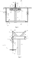
- FIG. 3 shows an embodiment of such a maintenance cage 5.
- the maintenance cage 5 has a maintenance cage structure, a hanging device 6 and a work platform 8.
- the hanging device 6 is designed for hanging the maintenance cage structure on the cable 3 of the cable car.
- the hanging device 6 preferably has a fastening mechanism 62 with which the maintenance cage 5 can be fastened to a hanging rod 61 for vehicles (cabins, chairlift, etc.) of the cable car, with the hanging rod 61 being fastened to the cable 3 .
- This attachment mechanism 62 may be, for example, a flange or an opening into which the hanger linkage can be inserted and attached, or any other attachment mechanism.
- the attachment mechanism 62 could also consist directly of a hanging linkage 61 which can be attached to the cable 3, for example with a clamp, coupling or coupling clamp.
- the hanging device 6 preferably has at least one joint 63, 64, which rotatably supports the maintenance basket structure with one, two or more degrees of freedom.
- the at least one joint 63, 64 preferably allows the maintenance basket structure or the maintenance basket 5 to be mounted so that it can rotate about a horizontal axis 63', which is aligned at right angles to the cable direction.
- the at least one joint 63, 64 preferably allows the maintenance cage 5 or the maintenance cage structure to be mounted so that it can rotate about a vertical axis 64'. This is particularly advantageous in the exemplary embodiment described below two hangers 6.
- the two joints 63 and 64 are provided for the two rotations. However, it is also possible to provide only one common joint for both rotations.
- the hanging device 6 preferably has two of the hanging devices 6 described above, so that the maintenance cage 5 can be stored at two fastening points along the cable 3 . Both suspension devices 6 are preferably attached to the same cable 3 . However, it is also possible to attach or guide the two suspension devices 6 to different cables, eg a traction cable and a carrying cable.
- the two attachment points of the maintenance basket 5 along the cable 3 are preferably located at the two extremities of the maintenance basket 5. The attachment of the maintenance basket 5 at two attachment points allows a stable (non-swaying) work platform 8, which is a great help for maintenance work.
- the maintenance cage structure is attached to the hanger 6 . If the hanging device 6 is attached to the cable 3 at only one attachment point, the maintenance cage structure is preferably attached to the hanging device 6 centered over the center of gravity of the maintenance cage 5 . If the hangers 6 are attached to the cable 3 with two hangers 6 at two attachment points, the maintenance basket structure is attached to the two hangers 6 (preferably at its extremities).
- the work platform 8 is now attached to the maintenance basket structure, so that maintenance work at the maintenance point can be carried out by the maintenance technician located on the work platform 8 .
- the working platform 8 is preferably longer than 2 meters (m), preferably longer than 3 m, preferably longer than 4 m.
- the length extends in principle in the direction of the cable 3.
- the working platform 8 is preferably wider than 50 centimeters (cm) , preferably wider than 80 cm, preferably wider than 1 m/100 cm.
- the width is generally perpendicular to the cable 3.
- the work platform 8 is perpendicular.
- the floor of the work platform 8 preferably has a grating on. The grating is preferably placed in all areas of the floor on which the maintenance technician can move.
- the grating has proven to be particularly advantageous, as it allows the maintenance technician to stand securely even in snow and contamination with slippery materials such as oil and grease.
- the working platform 8 preferably has a railing so that a maintenance technician standing on the working platform 8 can hold on and/or is protected against falling.
- the railing runs around the sides of the work platform 8 accessible to the maintenance technician.
- the work platform 8 preferably has a work table, preferably a workbench.
- the work table is preferably movably arranged on the work platform 8, e.g. on rollers and/or rails.
- the working platform 8 preferably has a ladder. This ladder is preferably integrated into the railing.
- the work platform 8 has a test bench for magneto-inductive material testing of parts of the cable car, in particular the sheave assembly, in particular axles, in particular the main axle 4, the rocker axles 23 and/or the roller axles 22.
- This test bench for magneto-inductive material testing is also known as the MT test bench.
- the magneto-inductive material test is preferably a magnetic powder test.
- the test bench is mobile on the work platform 8, so that the test bench can be moved to the recess 4' in the support structure 1 for material testing of the main axis 4 of the sheave assembly.
- the test bench is preferably attached to the work platform 8, preferably to the work table.
- the material test is preferably a non-destructive material test (ZfP). This is used, for example, to detect cracks in the part.
- the small parts cleaner is preferably designed to clean said parts using a cleaning fluid.
- the cleaning fluid is, for example, compressed air or a cleaning liquid.
- a grease-dissolving liquid is preferably used as the cleaning liquid in order to free the parts from contaminated oil or grease.
- the small parts cleaner preferably has a cleaning tool that Fluidly connected to a source or reservoir for the cleaning fluid, so that said parts can be cleaned with the cleaning tool and the cleaning fluid emerging from the cleaning tool.
- the small parts cleaner preferably also has a collecting device for collecting a drain liquid.
- the small parts cleaner and/or the cleaning tool is so mobile that it can be guided to the recess 4′ of the main axle 4 in order to clean the main axle 4 on site.
- the working platform 8 preferably has a plurality of transport boxes.
- the transport crates can preferably be attached to different positions on the work platform 8 .
- the transport crates are preferably attached to the railing 82 of the work platform 8 .
- the transport boxes are preferably attached to the railing 82 of the working platform 8 on the outside of the working platform 8 so that the transport boxes do not restrict the working space of the working platform 8 within the railing 82 .
- the transport crates are preferably closed all around (with the possible exception of a small opening on the underside for condensation), so that the transported goods are protected against wind and weather.
- the shipping crates are preferably attached to the railing 82 on the side of the work platform 8 facing away from the supports 1 (normally to the right in the forward direction of travel).
- Spare parts such as spare rollers 21, spare seesaws 24, 25 and spare axles 4, 22 and 23 are also transported in the maintenance basket 5 to exchange these parts if the inspection reveals damage to these inspected parts.
- the working platform 8 has holders for the spare parts on the side of the working platform 8 pointing towards the supports 1, preferably on the railing 82 there. These holders are preferably designed in such a way that the spare parts are held securely even when the work platform 8 is moved. These holders are preferably arranged on the inside of the railing 82 so that the weight of the spare parts serves as a counterweight for the maintenance basket 5 .
- the working platform 8 preferably also has maintenance tools, in particular testing and/or revision tools and/or consumables such as lubricants, slide bearings, screws, nuts, etc. These can, for example, be transported in the transport boxes and/or on the work table.
- the work platform 8 also has at least one safety device 9 such as cable pulls, load slings and/or hydraulic cylinders.
- This securing device(s) allow the working platform 8, the maintenance cage 5, the cable 3, the sheave assembly 2 and/or the rocker(s) 24, 25 to be secured to the support 1, in particular to the lifting yoke 13.
- a hydraulic cylinder is particularly advantageously used as the safety device 9 .
- a hydraulic power pack is used for actuating the hydraulic cylinder.
- a hydraulic unit is advantageously used to actuate a plurality of hydraulic cylinders. The hydraulic unit is preferably driven mechanically, i.e. by a service technician. However, an electric drive is also possible.
- the work platform 8 preferably has a hydraulic pump that pumps hydraulic fluid from a hydraulic accumulator into a hydraulic system.
- the hydraulic pump can be driven manually or by an electric motor.
- the hydraulic system has a distributor block that connects the hydraulic pump to a number of hydraulic consumers.
- the connection to the consumers can be fixed or, as is preferred, can be implemented as removable via connections.
- a consumer could be a hydraulic motor, for example, in order to actuate the lifting mechanism 7 or the further lifting mechanism.
- Other consumers could be hydraulic cylinders, which can be used as safety devices 9 as described above.
- the work platform 8 preferably has a power generator that generates the power required for the tools and/or the test bench.
- the power generator could possibly also drive the hydraulic pump directly.
- This additional lifting mechanism is, for example, a scissor lift.
- the lifting mechanism is arranged on the work platform 8 or the work table in such a way that it is below the cable 3 .
- the lifting mechanism can also be a crane.
- the crane preferably has a first support device, a second support device and a crane cross beam.
- the first support device is fastened or can be fastened on the working platform 8 .
- the second support device can be fastened or set down on the support structure 1, preferably on a flat platform (pedestal) of the support structure 1.
- the crane cross beam is arranged between the two support devices.
- the first and/or the The height of the second support device can be adjusted so that the crane crossbeam can be aligned horizontally.
- the first support device can be permanently mounted on the work platform 8 or on a structure of the work platform 8 that can be moved in the cable direction, so that the first support device only has to be adjusted in terms of its height and position in the cable direction and does not have to be mounted for every maintenance.
- the first supporting device or its movable structure is preferably mounted on the outside of the railing 82 of the working platform 8 or on the railing 82 . As a result, the space on the working platform 5 is not restricted by the crane. The first supporting device thus remains mounted when the maintenance cage 5 is moving.
- the first support device could also simply be supported within the railing 82 and/or on the floor of the work platform 8.
- the second support device is preferably supported on the support structure 1 .
- the first and/or second support device has two support legs, so that this support device stands more stably.
- the crossbeam and/or the second support device of the crane can be retracted or folded in or dismantled while the maintenance cage 5 is moving.
- the cross member can be shifted to the side of the maintenance cage 5 pointing away from the supports 1, so that the cross member, possibly with the second support device, does not get in the way while driving.
- a cable pull is preferably arranged on the crossbeam, with which parts can be lifted.
- the position of the cable pull on the crossbeam between the first and second support device can preferably be shifted (also under load) and fixed. This is preferably achieved by a sled or trolley that can be moved on the crane crossbeam and to which the cable pull is attached.
- the crane is preferably made of metal, preferably aluminum.
- the roller assembly 2 or parts of the roller assembly can be relieved in order to disassemble the roller assembly 2 for testing and/or maintenance.
- the further lifting mechanism can be used to support the rockers 25 and/or rollers 21 in order to remove the rocker and/or roller axles 22 and/or 23 for inspection and/or maintenance.
- the work platform 8 is movable relative to the basket structure. This allows the working platform 8 to be positioned better relative to the maintenance point (than the position of the working platform 8 specified by the maintenance cage structure).
- the work platform 8 can be attached to the support structure 1 during maintenance work will. This can be achieved, for example, with load slings that can be moved in length, cable pulls and/or hydraulic cylinders.
- the maintenance cage structure has a lifting mechanism 7 which can lift the work platform 8 relative to the maintenance cage structure. Thus, the work platform 8 can be brought closer to the maintenance point.
- a hydraulic mechanism is preferably used as the lifting mechanism 7 . However, mechanical lifting mechanisms are also possible.
- the lift mechanism 7 is actuated by the service technician's power.
- motorized actuation is also possible.
- the lifting mechanism comprises two lifting mechanisms so that the ends of the work platform 8 can be lifted in the cable direction differently from the basket structure (and preferably independently of each other).
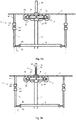
- a rope gradient can be compensated for when the maintenance basket structure is hung at two attachment points along the rope 3 . This is in 6 shown as an example.
- the basket structure is formed from two separate basket structures, each attached to one of the two hangers 6.
- Each basket structure has one of the elevating mechanisms 7 .
- the two lifting mechanisms 7 each have a lifting carriage 71 which is connected to a corresponding attachment point of the working platform 8 (preferably at its extremities in the cable direction). Between one or both lifting mechanisms 7, preferably between the lifting carriage or carriages 71, and the working platform 8, there is preferably also a joint 81 which allows the working platform 8 to rotate relative to the lifting carriage 71 about a horizontal axis 81'.
- Each of the two maintenance cage structures preferably forms a guide for the lifting carriage 71 .
- the two maintenance basket structures are only connected via the work platform 8. This saves a lot of weight.
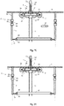
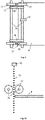
- FIG 8 shows another embodiment of a maintenance basket.
- the working platform 8 has a framework.
- the framework forms a railing 82 and a floor framework.
- the frame and/or that Floor frame is made of (welded) metal rods.
- the floor stand supports a floor surface on which the maintenance technician or technicians can stand and move and/or the work table.
- the floor frame preferably forms a frame linkage that surrounds/encircles the working platform 8 .
- the floor frame also has a further reinforcing or stiffening linkage between the frame linkage.
- the maintenance basket 5 in 8 has, like the last exemplary embodiment, two hanging devices 6, preferably on the two extremities (in the direction of the cable) of the maintenance cage 5. These are described in more detail here.
- the hanging device 6 has a hanging linkage 61 which can be attached to the rope 3 with a rope attachment mechanism such as a clamp, coupling or coupling clamp.
- the suspension linkage 61 has a roughly U-shape, so that the suspension linkage 61 is first led away from the rope 3 roughly horizontally (perpendicular to the rope direction), then is led roughly vertically downwards, and then roughly horizontally again (perpendicular to the rope direction ) is fed back under the rope 3 or under the rope attachment mechanism.
- the hanging device 6 preferably also has a cross member 65 .
- the cross brace 65 is attached under the hanger linkage 61 .
- the crossbeam 65 is preferably designed to carry the work platform 8, preferably the lifting mechanism 7, which the work platform 8 carries in a height-adjustable manner.
- the cross member 65 is preferably slidably attached to the hanger linkage 61 .
- the direction of displacement is preferably horizontal and/or perpendicular to the cable direction. This allows the working platform 8 to be optimally positioned in the displacement direction in relation to the support structure 1, in particular to the sheave assembly 2.
- the rope direction of the maintenance basket is defined by the rope attachment mechanism, by the direction defined by the two hangers 6 or by the attachment mechanism 62 even without being attached to a rope 3 of a cable car.
- the displacement device for displacing the working platform horizontally and/or perpendicularly to the cable direction could also be implemented differently.
- the hanger 6 described could also be used as a single hanger 6 for a maintenance basket.
- the hanging device 6 described can also be used in the embodiment of the maintenance basket 5 described above Figures 3 to 6 be used.
- the cable attachment mechanism preferably has a clamp coupling with which the hanging device 6 can be attached to the cable 3 .
- the suspension device 6 can be decoupled from the cable 3 .
- the rope attachment mechanism further comprises rolling means to guide the hanger 6 in a dedicated revolving guide while the clamp clutch is disengaged during the revolving.
- the rolling means preferably have two rollers arranged one behind the other in the cable direction.
- the embodiment in 8 shows another alternative for a lifting mechanism 7.
- the lifting mechanism 7 described below is preferably arranged on both extremities in the cable direction of the work platform 8, so that the distance between the work platform 8 and the cable 3 or from the suspension device 6 can be adjusted at both ends of the work platform 8 can.
- the lifting mechanism 7 described below can also be used in the embodiment of the maintenance basket 5 described above Figures 3 to 6 be used.
- the lifting mechanism 7 has a rope-like structure 75 which connects the work platform 8 to the maintenance basket structure or to the hanging device 6 .
- the cable-like structure 75 is preferably a chain, but can also be designed as a cable, wire cable or other flexible, longitudinally load-bearing, elongate structure.
- the chain is preferably a one-dimensional movable chain, preferably a roller chain. Chains that can be moved in one dimension have the advantage that the movement of the work platform 8 is not possible, or only possible in a damped manner, except in the plane of the chain movement. This prevents the working platform 8 from swaying too much under the cable 3.
- the direction of movement of the one-dimensional chain is preferably arranged parallel to the direction of the cable.
- the rope-like structure 75 preferably has two rope-like substructures 75 which connect the work platform 8 to the suspension device 6 (in particular to the crossbeam 65) on two sides of the rope 3 or the rope fastening mechanism.
- Two corners of the working platform 8 are preferably connected to two lateral extremities of the suspension device 6 and the crossbeam 61, respectively.
- the four corners of the working platform 8 are connected to the two suspension devices 6 by means of four cable-like substructures 75.
- the two rope-like substructures 75 are formed from a common rope-like structure 75 .
- the common rope-like structure 75 extends from (a first end) of the crossbar 65 to (a corner) of the work platform 8. There the rope-like structure 75 is deflected and guided back to the (middle of) the crossbar 65 . There the rope-like structure 75 is deflected again and guided back to (another corner) of the working platform 8 . There the cable-like structure 75 is deflected again and guided back to (the second end of) the cross brace 65 .
- the lifting mechanism 7 also has a mechanism that can change the length of the cable-like structure 75 between the suspension device 6 and the work platform 8 .
- the mechanism is preferably adapted to engage the cable-like structure and to displace the cable-like structure relative to the mechanism.
- This mechanism can be located either in the hanger 6 or on the work platform 8. In the embodiment in FIG 8 this mechanism is arranged in the hanging device 6, here the crossbeam 65, which shortens or lengthens the end(s) of the rope-like structure 75.
- the mechanism can be designed as a cable or chain hoist, for example.
- a disadvantage of the mechanism described is that the adjustability of the height is limited by the maximum length of the loop formed by the rope-like structure 75 . Due to the zigzag routing of the rope-like structure 75, a very long chain has to be used in order to achieve a large degree of adjustability. This leads to a great weight.
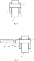
- Figures 9 to 12 show two alternative embodiments for the lifting mechanism 7.
- the two cable-like substructures 75 connect the suspension device 6 and the work platform 8 as described above.
- the second end of the cable-like substructure 75 opposite the first end, is connected to the mechanism on the other of the work platform 8 and the hanger 6.
- the mechanism can freely adjust the stopping point along the rope-like structure 75 and/or change the distance between the hanger 6 or the work platform 8. This allows the distance between the hanger 6 and the work platform 8 to be up to the length of the rope-like substructure 75 to be adjusted.
- the work platform 8 can be pulled up to the hanging devices 6 attached to the cable 3, for example without a crane or other lifting device, on a cable 3 of almost any height.
- the mechanism is preferably arranged on the work platform 8 . This allows the remainder of the cable-like substructure 75 to be suspended or stored beneath the mechanism or work platform.
- the second end of the cable-like substructure 75 can be transported, for example, in a box below the mechanism and/or below the work platform. Due to the open second end of the cable-like substructure 75, the two suspension devices 6 can also be attached to the cable 3 without the working platform 8 and the working platform 8 can subsequently be connected to the two mechanisms of the lifting mechanism 7 at the second ends of the four cable-like substructures 75.
- the mechanism has two support wheels 77 for each cable-like substructure 75.
- Each retaining wheel 77 engages with the rope-like substructure 75 and holds the rope-like substructure 75 in place.
- the rope-like substructure 75 runs between the two holding wheels 77 so that the rope-like substructure 75 cannot slip out of the two holding wheels 77 .
- the support wheels 77 are preferably arranged such that the gap between the two support wheels 77 through which the cable-like substructure 75 runs is located (in the vertical direction) below the attachment of the first end of the cable-like substructure 75 to the hanger 65.
- the cable-like structure 75 runs in a straight line in the vertical direction from the first end to the mechanism or the space between the two holding wheels 77 and also after the mechanism.
- the clamping means 78 or the bearing means 78 secure the axes of rotation of the two axes of rotation 76 on which the holding wheels 77 rotate in order to prevent the cable-like structure 75 from jumping out of the holding wheels 77 .
- the axes of rotation 76 are arranged parallel to one another.
- the axes of rotation 76 are arranged parallel to the narrow side of the work platform 8 and/or at right angles to the long side of the work platform 8 or to the cable direction.
- the axes of rotation 76 are rotatably mounted on the work platform 8 .
- the retaining wheels 77 are preferably sprockets, such as a Gear wheel for a roller chain or a pocket wheel for a link chain.
- clamping or friction wheels can be used as holding wheels 77, for example.
- the four support wheels 77 for the two cable-type substructures 75 run on the same two axles 76, so that the two support wheels 77 on both sides are rotated simultaneously and the distance between the hanger 6 and the work platform 8 is the same for both cable-type substructures 75.
- the mechanism further includes a rotating means 79 which causes the axle 76 or axles 76 to rotate.
- the rotating means 79 may have a transmission that reduces the effort required to rotate the axle 76 .
- the rotating means 76 is preferably hydraulic.
- the two axes 76 of the support wheels 77 are arranged at the same height.
- This allows the rope-like sub-structure 75 to be guided from the first end of the rope-like sub-structure 75 to the lower support wheel 77, around this lower support wheel 77, back to the upper support wheel 77, around the upper support wheel 77 back down.
- the deflection around each holding wheel 77 is preferably 180°.
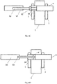
- a safety device 90 on the side of the upper support wheel 77 facing the second end of the rope-like substructure 75 can be used to prevent the rope-like substructure 75 from jumping out of the upper support wheel 77 .
- a similar safety device 90 could be used on the other side of the upper support wheel 77 and/or on one or both sides of the lower support wheel 77.
- the two axes of rotation 76 vertically one above the other, so that the cable-like substructure 75 wraps around the upper holding wheel 77 on a first horizontal side and around the lower holding wheel on a horizontal side opposite the first horizontal side 77 running.
- the rope-like substructure 75 is guided in an S-shape between the two holding wheels 77 .
- the weight of the work platform 8 causes the cable-like substructure 75 to be pressed against the support wheels 77 .
- the mechanism for adjusting the distance between the hanging device 6 and the work platform 8 on the hanging device 6 .
- the first end of the rope-like substructure 75 is then placed on the work platform 8 .
- the mechanism could consist of (only) two (instead of four) holding wheels, with a cable-like substructure 75 being deflected by 180° around each holding wheel.
- the second end of the cable-like substructure 75 can hang down freely after being deflected around the corresponding support wheel.
- the rope-like substructure 75 is guided from the working platform 8 to the corresponding holding wheel of the hanging device 6, deflected there by 180° and then guided downwards again (hanging freely).
- the two holding wheels for the two cable-like substructures 75 can be mounted on a common axle 76 .
- the common axis 76 can be mounted in the cross member 65 or at least parallel to it.
- the hanging devices 6 preferably have a joint (not shown) which allows rotation about a vertical axis.
- the joint could be located between the hanger linkage 61 and the cross member 65 or in the hanger linkage 61, for example.
- the maintenance work on cable cars can be significantly shortened and simplified if the maintenance technician is transported to the maintenance point with a maintenance basket hanging on the cable 3 of the cable car and carries out the necessary maintenance work on site.
- a maintenance basket for example the maintenance basket 5 is attached to the cable 3 of the cable car.
- the maintenance technician is then transported with the maintenance basket 5 to the maintenance location, e.g. the location of the sheave assembly 2 to be maintained (see Figure 7A ).
- the maintenance cage 5 has a movable working platform 8, the working platform 8 can still be positioned in such a way that the maintenance work on the sheave assembly 2 can be carried out easily (see 6 ).
- This is preferably realized by actuating the lifting mechanism 7 or the lifting mechanisms 7 .
- the maintenance basket 5 or the work platform 5 is preferably stabilized on the support structure 1. This is achieved, for example, by supporting rods.
- the maintenance work is now carried out.
- the first problem is that the main axle 4, on which the entire weight of the sheave assembly 2 and the load of the cable 3 rests, has to be removed.
- the sheave assembly 2 is secured at the maintenance point on the support structure 1, preferably on the lifting yoke 13.
- a safety device 9 is used for this purpose.
- the securing of the sheave assembly 2 is preferably based on suspending the load of the sheave assembly 2 on the support structure 1 or the lifting yoke 13 (see Figure 7B ).
- the cable pull also includes cable-like structures such as belts, chains, etc.
- the cable pull preferably has a cable-like structure 91 and a hydraulic cylinder 92 .
- the hydraulic cylinder 92 is a double acting, dual hydraulic cylinder.
- the securing can also be based on the support on the support structure 1 or the lifting yoke 13, e.g. if the cable 3 pushes the sheave assembly 2 upwards and the sheave assembly 2 has to be supported by the lifting yoke 13 in such a way that the main axis 4 can be removed from the roller battery 2 from the roller battery 2.
- the main axle 4 is now removed from the main axle opening 4' in the sheave assembly 2 and the support structure 1, while the sheave assembly 2 or at least the main rocker 24 is held in place by the securing device 9 (see Figure 7C ).
- the main axis 4 can now be cleaned and/or checked.
- Further (eg rocker and roller) axles 22 and 23 are preferably removed from the roller assembly 2, cleaned and/or checked.
- the further lifting mechanism of the working platform 8 can be used for this in order to support the rocker 25 or the roller 21 for the expansion of its axis 23 or 22. All removed axles 4, 22 and/or 23 are reinstalled in the sheave assembly 2 (see Figure 7D ).
- the maintenance technician can position the sheave assembly 2 relative to the support structure 1 in such a way that the main axis 4 can be reinserted into the main axis opening 4' of the sheave assembly 2 and the support structure 1. After that the Sheave assembly 2 unlocked so that the load rests on the main axle 4 again (see Figure 7E ).
- the maintenance technician can be transported with the maintenance basket 5 to the next maintenance location, e.g. the next sheave battery 2.
- one or two of the following two maintenance steps are carried out: cleaning and/or revision/inspection of the main axis 4 and cleaning and/or revision/inspection of the remaining sheave assembly 2. If both maintenance steps are carried out, their order is important not matter.
- the cable 3 is preferably secured with a securing device, preferably a hydraulic cylinder, on the support structure 1, preferably on the lifting yoke. Securing the rope 3 preferably involves lifting the rope 3 off the sheaves of the sheave assembly 2. However, this step is optional and the maintenance steps could also be performed with the rope 3 stored on the sheaves 21 of the sheave assembly 2.
- the rope is preferably secured to the support structure 1 with a safety device above the main axis 4 and/or in the middle of the main seesaw 24 .
- the cable 3 is preferably only raised to such an extent that the cable 3 remains guided on the first and second side of at least one of the rollers 21 mounted in the main seesaw 24 . This provides additional security for guiding the cable 3 and prevents the cable 3 from being threaded into the rollers 21 after the maintenance work has been carried out.
- the sheave assembly 2 is secured to the support structure 1, preferably to the lifting yoke 13, at the service point. This results in the load on the main axle 4 being reduced to such an extent that the main axle 4 can be moved or removed at the maintenance point.
- a safety device is used for this.
- the securing of the sheave assembly 2 is preferably based on suspending the load of the sheave assembly 2 on the support structure 1 or the lifting yoke 13.
- the safety device preferably has two sub-safety devices, preferably two hydraulic cylinders, which secure or suspend the two extremities in the rope direction of the main rocker 24 on the support structure 1 or the lifting yoke 13 .
- the sheave assembly 2 or the main rocker 24 could also be secured to the support structure 1 with the securing device 9 described above.
- the main axis 4 is preferably not completely removed from the recess 4' for the inspection or cleaning.
- the main axis 4 is mounted on a first side (e.g. pointing away from the support structure 1) and a second side (e.g. pointing towards the support structure 1) of the main rocker 24 in the recess 4' of the support structure 1 (see 13A ).
- the main axis 4 is now pushed out of the first side of the recess 4' in a first direction (perpendicular to the cable direction and/or away from the support structure 1).
- the main axis 4 is pushed out (only) far enough so that the main axis 4 is still located in the recess 4 ′ of the support structure 1 and the main rocker 24 on the first side.
- an auxiliary axle 96 with the same diameter or a (slightly) larger diameter than the main axle 4 is pushed into the recess 4' of the support structure 1 and the main rocker 24 from the second side (see Fig Figure 13D ).
- the auxiliary axle is pushed in far enough so that the auxiliary axle is located on the second side in the recess 4 ′ of both the support structure 1 and the main rocker 24 .
- the main axle 4 secures the main rocker 24 on the first side and the auxiliary axle secures the main rocker 24 on the second side.
- Figures 13B through 13D show a preferred method to partially slide the main axis 4 out of the recess 4' as described.
- the auxiliary axis 96 is arranged on the second side of the auxiliary axis 96 on the main axis 4, so that their ends lie on top of one another and their circumferences are arranged flush.
- a hydraulic cylinder 94 presses the auxiliary axle 96 against the main axle 4 so that the main axle 5 is pushed out on the first side and at the same time the auxiliary axle is pushed into the recess 4 ′ of the support structure 1 on the second side.
- the auxiliary axle 96 is pushed into the recess 4' until the auxiliary axle 4' is located both in the recess 4' of the support structure 1 and in the recess 4' of the main rocker 24 and supports the main rocker 24 on the second side (see Figure 13C ).
- the auxiliary axis preferably has a recess that runs through the axis direction.
- This recess is preferably arranged rotationally symmetrically, so that the auxiliary axis 96 is designed in the form of a hollow cylinder.
- the hydraulic cylinder 94 has a Stamp 93, which can be moved by the hydraulics of the hydraulic cylinder 94 and the auxiliary axle 96 can slide into the recess 4'.
- the ram 93 has an attachment 95 which widens the ram 93 to such an extent that the ram 93 cannot be inserted into the recess of the auxiliary axis 96 .
- the plunger 93 can be displaced in such a way that it presses against the auxiliary axis 96.
- the plunger 93 can also be made so wide that it does not fit into the recess 4'.
- the stamp 93 must have an attachment for the next step, which fits into the recess 4'.
- the punch 93 is now pushed through the continuous recess of the auxiliary axle 96 and now pushes the main axle 4 further out of the first side of the recess 4' (see Fig Figure 13D ).
- the main axis 4 is pushed out only so far that the main axis 4 is still mounted in the recess 4 ′ of the main rocker and in the recess 4 ′ of the first side of the support structure 1 .
- the main rocker 24 remains secured on both sides by the auxiliary axle 96 and the main axle 4 partially pushed out.
- auxiliary axle 96 can be made relatively short and thus weight-saving.
- the auxiliary axle 96 can be easily inserted on both sides even if there is little space.
- the auxiliary axis 96 could also be longer, so that the punch 93 does not have to be guided through the auxiliary axis 96 .
- the main axis 4 could also be pushed out directly with the hydraulic cylinder. The part of the main axis 4 protruding from the first side can now be subjected to cleaning and/or testing. For cleaning, the small parts cleaner and/or its cleaning tool is guided to the main axis 4 protruding from the recess 4 ′ of the support structure 1 .
- the test bench is guided to the main axis 4 protruding from the recess 4′ of the support structure 1 and the crack test is carried out there.
- the slide bearing in the support structure 1 and/or in the main rocker 24 can now be removed on the second side. If the sheave assembly is secured on the second side with the auxiliary axle 96, the auxiliary axle 96 must be removed for this purpose. Since the sheave assembly is further secured by the at least one safety device on the support device 1, in particular the lifting yoke 13, and/or by the main axis 4 on the first side on the support device 1, this is possible. Since the auxiliary axle 96 has a continuous recess, one can reach behind the auxiliary axle 96 through the continuous recess and pull it out.
- Hydraulic cylinders used for pushing in can be operated in two directions and can thus also be used to pull out the auxiliary axle 96.
- the plain bearing is usually replaced (or cleaned and/or checked) and reinserted into the recess 4' of the support structure 1 and/or the sheave assembly 2.
- the main axis 4 is pushed back completely into the recess 4 ′ of the main rocker 24 and the support structure 1 . This can be done with the help of the hydraulic cylinder 94 now located on the first side. If the sheave assembly is not perfectly centered, it will be difficult to insert the main axle 4 and this can lead to damage to the plain bearing.
- the auxiliary axle 96 is preferably pushed back into the recess 4' of the support structure 1 and the sheave assembly 2/the main rocker 24 on the second side.
- the recess 4' is centered with respect to the recess 4' of the sheave assembly 2 and the main axis 4 can now simply be pushed into the recess 4' of the sheave assembly 2 and the second side of the support structure 1.
- the auxiliary axle is pushed back out of the recess 4' on the second side.
- the diameter of the auxiliary axis 96 is preferably slightly larger than the diameter of the main axis 4, so that the auxiliary axis 96 brings about optimal centering.
- the auxiliary axis 96 can thus be used both for additional securing of the sheave assembly 2 and for better centering of the recesses 4 ′ of the sheave assembly 2 and the support structure 1 .
- the process of centering the recesses 4' and inserting the main axis 4 often took more than an hour in the prior art. This process can be significantly shortened by the method described. However, it is also possible to carry out the process without the auxiliary axis 96 .
- the same procedure is now repeated analogously in the second direction.
- the main axis 4 is now pushed out of the second side of the recess 4' in a second direction (perpendicular to the cable direction and/or away from the support structure 1).
- the main axis 4 is pushed out (only) so far that the main axis 4 is still located in the recess 4 ′ of the support structure 1 and the main rocker 24 on the second side.
- the auxiliary axle is pushed into the recess 4′ of the support structure 1 and the main rocker 24 from the first side.
- the auxiliary axle is pushed in far enough so that the auxiliary axle is located on the second side in the recess 4 ′ of both the support structure 1 and the main rocker 24 .
- the part of the main axis 4 protruding from the second side can now be subjected to cleaning and/or testing.
- the main axis 4 is pushed back completely into the recess 4' of the main rocker 24 and the support structure 1 (in the first direction).
- the auxiliary axle is pushed out of the recess 4' in the first side.
- the entire main axle 4 can thus be checked and/or cleaned without having to remove it completely from the recess 4′ if the examination of the main axle 4 shows that it is ok. Otherwise, this is pushed out completely and replaced by a replacement main axle 4.
- the main seesaw 24 is preferably moved on a first side/extremity in the cable direction (e.g. the mountain side) of the main seesaw 24 with the safety device to the support structure 1, preferably the lifting yoke 13 in such a way that at least one of the rollers on the first side is in the cable direction of the main seesaw 24 is pressed against the rope 3.
- the roller assembly 2 or the main rocker 24 rotates about the main axis 4 and the cable 3 releases the rollers 21 on the opposite, second side (eg the valley side).
- the at least one rocker 25 on the second side of the main rocker 24 is secured with the additional lifting mechanism, preferably the crane, so that the at least one axle 23 is load-free.
- the at least one axle 23, which supports the at least one rocker 25, can now be removed.
- the rocker 25 mounted on the removed axle 23 can be lowered onto the working platform 8, disassembled, its individual parts cleaned, checked and possibly replaced, reassembled and again with the also cleaned and checked axle 23 back in the main rocker 24 are attached.
- the main seesaw 24 on the second side of the main seesaw 24 is preferably moved to the support structure 1, preferably the lifting yoke 13, with the safety device in such a way that at least one of the rollers 21 on the second side is pressed against the rope 3 in the direction of the rope of the main seesaw 24.
- the at least one rocker 25 which is mounted on the second side in the cable direction of the main rocker 24, can now be subjected to cleaning and testing.
- the at least one rocker 25 on the first side of the main rocker 24 is secured with the additional lifting mechanism, preferably the crane, so that the at least one axle 23 is load-free.
- the same maintenance steps as on the second side are now carried out on the first side in the rope direction.
- the safety device on the second side of the main seesaw 24 is moved back again, so that the cable 3 gets back into at least one of the rollers 21 on the first side of the main seesaw 24 .
Landscapes
- Engineering & Computer Science (AREA)
- Transportation (AREA)
- Mechanical Engineering (AREA)
- Bridges Or Land Bridges (AREA)
- Vehicle Cleaning, Maintenance, Repair, Refitting, And Outriggers (AREA)
Applications Claiming Priority (3)
| Application Number | Priority Date | Filing Date | Title |
|---|---|---|---|
| CH01755/16A CH713297A2 (de) | 2016-12-29 | 2016-12-29 | Verfahren und Wartungskorb zur Wartung einer Seilbahn. |
| EP17832574.2A EP3562726B2 (fr) | 2016-12-29 | 2017-12-29 | Nacelle de maintenance et procédé de maintenance d'un téléphérique |
| PCT/IB2017/058511 WO2018122790A1 (fr) | 2016-12-29 | 2017-12-29 | Nacelle de maintenance et procédé de maintenance d'un téléphérique |
Related Parent Applications (2)
| Application Number | Title | Priority Date | Filing Date |
|---|---|---|---|
| EP17832574.2A Division-Into EP3562726B2 (fr) | 2016-12-29 | 2017-12-29 | Nacelle de maintenance et procédé de maintenance d'un téléphérique |
| EP17832574.2A Division EP3562726B2 (fr) | 2016-12-29 | 2017-12-29 | Nacelle de maintenance et procédé de maintenance d'un téléphérique |
Publications (4)
| Publication Number | Publication Date |
|---|---|
| EP4005899A1 true EP4005899A1 (fr) | 2022-06-01 |
| EP4005899C0 EP4005899C0 (fr) | 2024-04-24 |
| EP4005899B1 EP4005899B1 (fr) | 2024-04-24 |
| EP4005899B8 EP4005899B8 (fr) | 2024-05-29 |
Family
ID=61007730
Family Applications (2)
| Application Number | Title | Priority Date | Filing Date |
|---|---|---|---|
| EP17832574.2A Active EP3562726B2 (fr) | 2016-12-29 | 2017-12-29 | Nacelle de maintenance et procédé de maintenance d'un téléphérique |
| EP22152686.6A Active EP4005899B8 (fr) | 2016-12-29 | 2017-12-29 | Procédé d'entretien d'un téléphérique |
Family Applications Before (1)
| Application Number | Title | Priority Date | Filing Date |
|---|---|---|---|
| EP17832574.2A Active EP3562726B2 (fr) | 2016-12-29 | 2017-12-29 | Nacelle de maintenance et procédé de maintenance d'un téléphérique |
Country Status (3)
| Country | Link |
|---|---|
| EP (2) | EP3562726B2 (fr) |
| CH (1) | CH713297A2 (fr) |
| WO (1) | WO2018122790A1 (fr) |
Families Citing this family (1)
| Publication number | Priority date | Publication date | Assignee | Title |
|---|---|---|---|---|
| AT527220B1 (de) * | 2023-11-15 | 2024-12-15 | Innova Patent Gmbh | Vorrichtung zur Lagerung einer Rollenbatterie an einer Halteeinrichtung |
Citations (5)
| Publication number | Priority date | Publication date | Assignee | Title |
|---|---|---|---|---|
| JPH02104374A (ja) * | 1988-10-14 | 1990-04-17 | Mitsubishi Heavy Ind Ltd | ゴンドラリフト用救助装置 |
| EP0683079A1 (fr) | 1994-05-18 | 1995-11-22 | Garaventa Holding Ag | Véhicule de sauvetage pour un téléphérique |
| EP2301819A2 (fr) | 2009-09-24 | 2011-03-30 | Innova Patent GmbH | Procédé et dispositif destinés au changement des batteries de galets d'un téléphérique |
| EP2502799A1 (fr) | 2011-03-23 | 2012-09-26 | Pomagalski | Installation de transport par câble aérien munie d'un véhicule de maintenance |
| WO2015003196A1 (fr) | 2013-07-11 | 2015-01-15 | Innova Patent Gmbh | Dispositif permettant de remplacer des batteries de galets |
Family Cites Families (8)
| Publication number | Priority date | Publication date | Assignee | Title |
|---|---|---|---|---|
| DE7304936U (de) | 1974-03-28 | Morsbach P | Bahnanlage mit einem geschlossenen Schienensystem nach Art einer Achterbahn | |
| GB917597A (en) | 1960-07-20 | 1963-02-06 | Bagshawe & Company Ltd | Improvements in and relating to conveyor systems |
| US4995319A (en) | 1989-06-09 | 1991-02-26 | Poma Of America, Inc. | Sheave train assembly for cable transportation systems |
| DE9106797U1 (de) | 1991-06-03 | 1992-10-01 | Rsl Logistik Gmbh & Co, 8910 Landsberg | Fördermittel |
| FR2920123B1 (fr) | 2007-08-20 | 2009-10-09 | Pomagalski Sa | Vehicule d'intervention le long d'un cable aerien d'une installation de remontee mecanique |
| DE102014011971B3 (de) | 2014-08-15 | 2015-09-17 | Eisenmann Ag | Transportvorrichtung mit mehreren Wagen und Transportsystem |
| EP3206930B1 (fr) | 2014-10-14 | 2019-12-18 | Wopfner, Kurt | Poulie fixe, en particulier pour un accumulateur à rouleaux d'un dispositif téléphérique |
| AT517045B1 (de) | 2015-04-14 | 2018-06-15 | Kurt Wopfner | Lagerbock zur Lagerung einer Rollenbatterie |
-
2016
- 2016-12-29 CH CH01755/16A patent/CH713297A2/de not_active Application Discontinuation
-
2017
- 2017-12-29 EP EP17832574.2A patent/EP3562726B2/fr active Active
- 2017-12-29 WO PCT/IB2017/058511 patent/WO2018122790A1/fr not_active Ceased
- 2017-12-29 EP EP22152686.6A patent/EP4005899B8/fr active Active
Patent Citations (5)
| Publication number | Priority date | Publication date | Assignee | Title |
|---|---|---|---|---|
| JPH02104374A (ja) * | 1988-10-14 | 1990-04-17 | Mitsubishi Heavy Ind Ltd | ゴンドラリフト用救助装置 |
| EP0683079A1 (fr) | 1994-05-18 | 1995-11-22 | Garaventa Holding Ag | Véhicule de sauvetage pour un téléphérique |
| EP2301819A2 (fr) | 2009-09-24 | 2011-03-30 | Innova Patent GmbH | Procédé et dispositif destinés au changement des batteries de galets d'un téléphérique |
| EP2502799A1 (fr) | 2011-03-23 | 2012-09-26 | Pomagalski | Installation de transport par câble aérien munie d'un véhicule de maintenance |
| WO2015003196A1 (fr) | 2013-07-11 | 2015-01-15 | Innova Patent Gmbh | Dispositif permettant de remplacer des batteries de galets |
Also Published As
| Publication number | Publication date |
|---|---|
| EP3562726B1 (fr) | 2022-03-30 |
| EP3562726B2 (fr) | 2024-03-27 |
| EP3562726A1 (fr) | 2019-11-06 |
| WO2018122790A1 (fr) | 2018-07-05 |
| EP4005899B8 (fr) | 2024-05-29 |
| CH713297A2 (de) | 2018-06-29 |
| EP4005899C0 (fr) | 2024-04-24 |
| EP4005899B1 (fr) | 2024-04-24 |
Similar Documents
| Publication | Publication Date | Title |
|---|---|---|
| EP0389516A1 (fr) | Systeme de stockage a convoyeur, notamment systeme de stationnement de vehicules. | |
| DE202010008730U1 (de) | Transporteinrichtung für Druckplatten | |
| DE102017102930B4 (de) | Hebevorrichtung und Anlage zum Transportieren von Stückgut | |
| EP4172096A1 (fr) | Procédé pour construire un système d'ascenseur, et système d'ascenseur apte à mettre en oeuvre le procédé | |
| DE3420737A1 (de) | Zusatzeinrichtung fuer hoehenverstellbare arbeitsgerueste | |
| EP3562726B1 (fr) | Nacelle de maintenance et procédé de maintenance d'un téléphérique | |
| DE202009016924U1 (de) | Zusammenlegbarer Kleinkran | |
| DE202005019439U1 (de) | Hebebühne | |
| DE3608096C2 (fr) | ||
| DE909077C (de) | Zerlegbares Hebezeug zum Auf- und Abladen von Gleisschienen auf Eisenbahnfahrzeuge | |
| DE2029681B2 (de) | Krangehänge | |
| DE202011101434U1 (de) | Kompakt-Greiferlaufkatze | |
| AT396585B (de) | Einrichtung zur bedienung von lagerregalen | |
| DE102006062245B4 (de) | Wartungsgleisanlage | |
| DE102005014230B4 (de) | Vorrichtung zum Einbringen von Bohrungen in einen Hang | |
| EP0683079A1 (fr) | Véhicule de sauvetage pour un téléphérique | |
| DE2629253C3 (de) | Vorrichtung zum Befördern von Baumaterial durch eine Maueröffnung in ein Gebäude | |
| DE1508161C (de) | Blaslanzenvonichtung fur metallur gische Gefaßstande | |
| DE2711115C2 (de) | Hebevorrichtung für Förderkörbe, -gefäße und Gegengewichte | |
| DE102021006101A1 (de) | Arbeitsbühne für Brücken | |
| DE947959C (de) | Vorrichtung zur Foerderung von Lasten | |
| DE2326400C2 (de) | Außenbefahranlage | |
| DE4332689A1 (de) | Verfahren und Vorrichtung zum Verlegen von Rohren | |
| DE1458921C (de) | Blaslanzentragvornchtung für Kon verter | |
| DE585434C (de) | Heb- und senkbare Tragvorrichtung fuer elektrische Apparate |
Legal Events
| Date | Code | Title | Description |
|---|---|---|---|
| PUAI | Public reference made under article 153(3) epc to a published international application that has entered the european phase |
Free format text: ORIGINAL CODE: 0009012 |
|
| STAA | Information on the status of an ep patent application or granted ep patent |
Free format text: STATUS: THE APPLICATION HAS BEEN PUBLISHED |
|
| AC | Divisional application: reference to earlier application |
Ref document number: 3562726 Country of ref document: EP Kind code of ref document: P |
|
| AK | Designated contracting states |
Kind code of ref document: A1 Designated state(s): AL AT BE BG CH CY CZ DE DK EE ES FI FR GB GR HR HU IE IS IT LI LT LU LV MC MK MT NL NO PL PT RO RS SE SI SK SM TR |
|
| STAA | Information on the status of an ep patent application or granted ep patent |
Free format text: STATUS: REQUEST FOR EXAMINATION WAS MADE |
|
| 17P | Request for examination filed |
Effective date: 20221123 |
|
| RBV | Designated contracting states (corrected) |
Designated state(s): AL AT BE BG CH CY CZ DE DK EE ES FI FR GB GR HR HU IE IS IT LI LT LU LV MC MK MT NL NO PL PT RO RS SE SI SK SM TR |
|
| GRAP | Despatch of communication of intention to grant a patent |
Free format text: ORIGINAL CODE: EPIDOSNIGR1 |
|
| STAA | Information on the status of an ep patent application or granted ep patent |
Free format text: STATUS: GRANT OF PATENT IS INTENDED |
|
| GRAS | Grant fee paid |
Free format text: ORIGINAL CODE: EPIDOSNIGR3 |
|
| INTG | Intention to grant announced |
Effective date: 20240222 |
|
| GRAA | (expected) grant |
Free format text: ORIGINAL CODE: 0009210 |
|
| STAA | Information on the status of an ep patent application or granted ep patent |
Free format text: STATUS: THE PATENT HAS BEEN GRANTED |
|
| AC | Divisional application: reference to earlier application |
Ref document number: 3562726 Country of ref document: EP Kind code of ref document: P |
|
| AK | Designated contracting states |
Kind code of ref document: B1 Designated state(s): AL AT BE BG CH CY CZ DE DK EE ES FI FR GB GR HR HU IE IS IT LI LT LU LV MC MK MT NL NO PL PT RO RS SE SI SK SM TR |
|
| REG | Reference to a national code |
Ref country code: GB Ref legal event code: FG4D Free format text: NOT ENGLISH |
|
| REG | Reference to a national code |
Ref country code: CH Ref legal event code: EP |
|
| REG | Reference to a national code |
Ref country code: DE Ref legal event code: R096 Ref document number: 502017016073 Country of ref document: DE |
|
| RAP4 | Party data changed (patent owner data changed or rights of a patent transferred) |
Owner name: COLOMBO REVIGONDOLA AG |
|
| REG | Reference to a national code |
Ref country code: CH Ref legal event code: PK Free format text: BERICHTIGUNG B8 |
|
| REG | Reference to a national code |
Ref country code: IE Ref legal event code: FG4D Free format text: LANGUAGE OF EP DOCUMENT: GERMAN |
|
| U01 | Request for unitary effect filed |
Effective date: 20240424 |
|
| U07 | Unitary effect registered |
Designated state(s): AT BE BG DE DK EE FI FR IT LT LU LV MT NL PT SE SI Effective date: 20240503 |
|
| PG25 | Lapsed in a contracting state [announced via postgrant information from national office to epo] |
Ref country code: IS Free format text: LAPSE BECAUSE OF FAILURE TO SUBMIT A TRANSLATION OF THE DESCRIPTION OR TO PAY THE FEE WITHIN THE PRESCRIBED TIME-LIMIT Effective date: 20240824 |
|
| PG25 | Lapsed in a contracting state [announced via postgrant information from national office to epo] |
Ref country code: HR Free format text: LAPSE BECAUSE OF FAILURE TO SUBMIT A TRANSLATION OF THE DESCRIPTION OR TO PAY THE FEE WITHIN THE PRESCRIBED TIME-LIMIT Effective date: 20240424 |
|
| PG25 | Lapsed in a contracting state [announced via postgrant information from national office to epo] |
Ref country code: GR Free format text: LAPSE BECAUSE OF FAILURE TO SUBMIT A TRANSLATION OF THE DESCRIPTION OR TO PAY THE FEE WITHIN THE PRESCRIBED TIME-LIMIT Effective date: 20240725 |
|
| PG25 | Lapsed in a contracting state [announced via postgrant information from national office to epo] |
Ref country code: ES Free format text: LAPSE BECAUSE OF FAILURE TO SUBMIT A TRANSLATION OF THE DESCRIPTION OR TO PAY THE FEE WITHIN THE PRESCRIBED TIME-LIMIT Effective date: 20240424 |
|
| PG25 | Lapsed in a contracting state [announced via postgrant information from national office to epo] |
Ref country code: PL Free format text: LAPSE BECAUSE OF FAILURE TO SUBMIT A TRANSLATION OF THE DESCRIPTION OR TO PAY THE FEE WITHIN THE PRESCRIBED TIME-LIMIT Effective date: 20240424 |
|
| PG25 | Lapsed in a contracting state [announced via postgrant information from national office to epo] |
Ref country code: PL Free format text: LAPSE BECAUSE OF FAILURE TO SUBMIT A TRANSLATION OF THE DESCRIPTION OR TO PAY THE FEE WITHIN THE PRESCRIBED TIME-LIMIT Effective date: 20240424 Ref country code: NO Free format text: LAPSE BECAUSE OF FAILURE TO SUBMIT A TRANSLATION OF THE DESCRIPTION OR TO PAY THE FEE WITHIN THE PRESCRIBED TIME-LIMIT Effective date: 20240724 Ref country code: IS Free format text: LAPSE BECAUSE OF FAILURE TO SUBMIT A TRANSLATION OF THE DESCRIPTION OR TO PAY THE FEE WITHIN THE PRESCRIBED TIME-LIMIT Effective date: 20240824 Ref country code: HR Free format text: LAPSE BECAUSE OF FAILURE TO SUBMIT A TRANSLATION OF THE DESCRIPTION OR TO PAY THE FEE WITHIN THE PRESCRIBED TIME-LIMIT Effective date: 20240424 Ref country code: GR Free format text: LAPSE BECAUSE OF FAILURE TO SUBMIT A TRANSLATION OF THE DESCRIPTION OR TO PAY THE FEE WITHIN THE PRESCRIBED TIME-LIMIT Effective date: 20240725 Ref country code: ES Free format text: LAPSE BECAUSE OF FAILURE TO SUBMIT A TRANSLATION OF THE DESCRIPTION OR TO PAY THE FEE WITHIN THE PRESCRIBED TIME-LIMIT Effective date: 20240424 Ref country code: RS Free format text: LAPSE BECAUSE OF FAILURE TO SUBMIT A TRANSLATION OF THE DESCRIPTION OR TO PAY THE FEE WITHIN THE PRESCRIBED TIME-LIMIT Effective date: 20240724 |
|
| REG | Reference to a national code |
Ref country code: DE Ref legal event code: R026 Ref document number: 502017016073 Country of ref document: DE |
|
| PG25 | Lapsed in a contracting state [announced via postgrant information from national office to epo] |
Ref country code: CZ Free format text: LAPSE BECAUSE OF FAILURE TO SUBMIT A TRANSLATION OF THE DESCRIPTION OR TO PAY THE FEE WITHIN THE PRESCRIBED TIME-LIMIT Effective date: 20240424 |
|
| PG25 | Lapsed in a contracting state [announced via postgrant information from national office to epo] |
Ref country code: RO Free format text: LAPSE BECAUSE OF FAILURE TO SUBMIT A TRANSLATION OF THE DESCRIPTION OR TO PAY THE FEE WITHIN THE PRESCRIBED TIME-LIMIT Effective date: 20240424 Ref country code: SK Free format text: LAPSE BECAUSE OF FAILURE TO SUBMIT A TRANSLATION OF THE DESCRIPTION OR TO PAY THE FEE WITHIN THE PRESCRIBED TIME-LIMIT Effective date: 20240424 |
|
| PG25 | Lapsed in a contracting state [announced via postgrant information from national office to epo] |
Ref country code: SM Free format text: LAPSE BECAUSE OF FAILURE TO SUBMIT A TRANSLATION OF THE DESCRIPTION OR TO PAY THE FEE WITHIN THE PRESCRIBED TIME-LIMIT Effective date: 20240424 |
|
| PG25 | Lapsed in a contracting state [announced via postgrant information from national office to epo] |
Ref country code: SM Free format text: LAPSE BECAUSE OF FAILURE TO SUBMIT A TRANSLATION OF THE DESCRIPTION OR TO PAY THE FEE WITHIN THE PRESCRIBED TIME-LIMIT Effective date: 20240424 Ref country code: SK Free format text: LAPSE BECAUSE OF FAILURE TO SUBMIT A TRANSLATION OF THE DESCRIPTION OR TO PAY THE FEE WITHIN THE PRESCRIBED TIME-LIMIT Effective date: 20240424 Ref country code: RO Free format text: LAPSE BECAUSE OF FAILURE TO SUBMIT A TRANSLATION OF THE DESCRIPTION OR TO PAY THE FEE WITHIN THE PRESCRIBED TIME-LIMIT Effective date: 20240424 Ref country code: CZ Free format text: LAPSE BECAUSE OF FAILURE TO SUBMIT A TRANSLATION OF THE DESCRIPTION OR TO PAY THE FEE WITHIN THE PRESCRIBED TIME-LIMIT Effective date: 20240424 |
|
| PLBI | Opposition filed |
Free format text: ORIGINAL CODE: 0009260 |
|
| PLAX | Notice of opposition and request to file observation + time limit sent |
Free format text: ORIGINAL CODE: EPIDOSNOBS2 |
|
| U20 | Renewal fee for the european patent with unitary effect paid |
Year of fee payment: 8 Effective date: 20241230 |
|
| PLBB | Reply of patent proprietor to notice(s) of opposition received |
Free format text: ORIGINAL CODE: EPIDOSNOBS3 |
|
| 26 | Opposition filed |
Opponent name: DOPPELMAYR SEILBAHNEN GMBH Effective date: 20250122 |
|
| PG25 | Lapsed in a contracting state [announced via postgrant information from national office to epo] |
Ref country code: MC Free format text: LAPSE BECAUSE OF FAILURE TO SUBMIT A TRANSLATION OF THE DESCRIPTION OR TO PAY THE FEE WITHIN THE PRESCRIBED TIME-LIMIT Effective date: 20240424 |
|
| GBPC | Gb: european patent ceased through non-payment of renewal fee |
Effective date: 20241229 |
|
| PG25 | Lapsed in a contracting state [announced via postgrant information from national office to epo] |
Ref country code: GB Free format text: LAPSE BECAUSE OF NON-PAYMENT OF DUE FEES Effective date: 20241229 |
|
| PG25 | Lapsed in a contracting state [announced via postgrant information from national office to epo] |
Ref country code: IE Free format text: LAPSE BECAUSE OF NON-PAYMENT OF DUE FEES Effective date: 20241229 |
|
| REG | Reference to a national code |
Ref country code: CH Ref legal event code: U11 Free format text: ST27 STATUS EVENT CODE: U-0-0-U10-U11 (AS PROVIDED BY THE NATIONAL OFFICE) Effective date: 20260101 |
|
| U20 | Renewal fee for the european patent with unitary effect paid |
Year of fee payment: 9 Effective date: 20251218 |
|
| PGFP | Annual fee paid to national office [announced via postgrant information from national office to epo] |
Ref country code: CH Payment date: 20260101 Year of fee payment: 9 |