EP0683322A2 - Dispositif de pompage - Google Patents
Dispositif de pompage Download PDFInfo
- Publication number
- EP0683322A2 EP0683322A2 EP95106941A EP95106941A EP0683322A2 EP 0683322 A2 EP0683322 A2 EP 0683322A2 EP 95106941 A EP95106941 A EP 95106941A EP 95106941 A EP95106941 A EP 95106941A EP 0683322 A2 EP0683322 A2 EP 0683322A2
- Authority
- EP
- European Patent Office
- Prior art keywords
- pump unit
- separating
- unit according
- separating container
- pump
- Prior art date
- Legal status (The legal status is an assumption and is not a legal conclusion. Google has not performed a legal analysis and makes no representation as to the accuracy of the status listed.)
- Granted
Links
Images

Classifications
-
- F—MECHANICAL ENGINEERING; LIGHTING; HEATING; WEAPONS; BLASTING
- F04—POSITIVE - DISPLACEMENT MACHINES FOR LIQUIDS; PUMPS FOR LIQUIDS OR ELASTIC FLUIDS
- F04C—ROTARY-PISTON, OR OSCILLATING-PISTON, POSITIVE-DISPLACEMENT MACHINES FOR LIQUIDS; ROTARY-PISTON, OR OSCILLATING-PISTON, POSITIVE-DISPLACEMENT PUMPS
- F04C19/00—Rotary-piston pumps with fluid ring or the like, specially adapted for elastic fluids
- F04C19/001—General arrangements, plants, flowsheets
Definitions
- the invention relates to a pump unit according to the preamble of claim 1.
- Such a pump unit is known from DE-A-24 60 268.
- the separator tank is designed in the form of a horizontal U on which the pump unit is placed.
- the gas-liquid mixture expelled by the liquid ring pump is introduced into the separating container at the free end of one U-leg via an inlet opening provided there and at the free end of the other U-leg the gas emerges from the separating container via a corresponding outlet opening.
- this separating container there is a continuous distance between the inlet opening and the outlet opening via the gas space of the separating container, over which the airborne sound generated by the pump can spread undamped.
- the invention has for its object to design a pump unit of the generic type so that both effective sound damping and starting the liquid ring pump is possible without additional measures.
- the problem is solved by the features specified in the characterizing part of claim 1.
- the design of the separating tank in the form of a standing L or U ensures that the horizontally lying part of the separating tank is completely filled with operating fluid.
- this flows through the liquid contained in the separating container at least partially in a horizontal or approximately horizontal direction. This leads to a slowdown in the flow velocity.
- This reduced flow speed the long path of the gas through the liquid to the entry into the gas space of the separating tank and the multiple gas deflection result in a very high level of sound damping of the airborne sound acting at the blade frequency.
- the structure-borne noise is strongly damped by the separating container, which is designed as a chamber and partially filled with liquid. So no structure-borne sound-breaking connecting elements to the foundation and between the pipe parts to be connected to the inlet and outlet opening of the liquid ring pump are required.
- the separator tank Due to the L- or U-shape of the separator tank, which also extends in the vertical direction, it is possible to select the liquid level in the separator tank so that the liquid ring pump is still partially filled with liquid while the unit is at a standstill. Because of this partial filling, the liquid ring pump can thus be started up without special additional measures.
- the one or more vertical legs of the separating container form mechanical protection for the pump unit mounted on the separating container.
- the outlet opening is advantageously provided on the head side of the or one of the vertical legs of the L-shaped or U-shaped separating tank. This results in a space only filled with gas in the separating tank above the level of the liquid.
- the mechanical strength of the unit can be increased in that the front and / or rear of the separating container is closed off by means of a wall part in the case of a U-shaped design. Furthermore, in such an embodiment of the pump unit, the pump unit is enclosed on at least three sides by the separating container, which results in improved sound insulation.
- the wall part is provided with an opening enclosing the fan hood of the drive motor, then this wall part simultaneously forms a barrier between the intake and exhaust side of the motor fan.
- the wall part is designed as a chamber part connecting the two legs of the separating container, the flow connection between the two vertical legs of the U-shaped separating container is given without separate components.
- the peripheral wall of the opening provided in it can form the air duct for the fan wheel of a cooling fan.
- Both the mechanical protection for the pump unit and the soundproofing of the pump unit are further improved in that, in the case of a U-shaped design of the separating container, a cover part is placed on its two vertical legs.
- the separation of liquid droplets entrained in the gas bubbles and the soundproofing of the gas noises can be further improved by installing one or more baffles in the separation container on the route between its inlet and its outlet. Such baffles also calm the liquid level.
- cooling and / or stiffening ribs are provided on the separating tank. Such ribs can simultaneously fulfill the dual function of cooling and stiffening the separating tank.
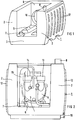
- the wall part 9 is designed as a hollow chamber part, so that a flow connection between the two vertical U-legs 2 is established via this wall part 9.
- Cooling or stiffening ribs 12 are formed on the outside of the vertical U-legs 2.
- the liquid ring pump 5 has an intake port 13 and an outlet port 14.
- the outlet connection 14 of the liquid ring pump 5 is connected to the first pipe connection 7 of the separating container 1 via corresponding pipe parts 15.
- a drain port 16 is arranged thereon.
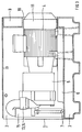
- the liquid ring pump 5 Via its intake port 13, the liquid ring pump 5 sucks in the gas to be compressed, which after compression in the liquid ring pump 5 is expelled via its outlet port 14 together with operating liquid and introduced via the pipe parts 15 and the first pipe port 7 into the separating container 1 below the liquid level.
- the gas flows through the horizontal U-yoke 3 of the separating tank 1, and then in the vertical U-legs 2 rise in the space above the liquid level of the liquid contained in the separating container 1, which is only filled with gas.
- the flow velocity of the gas When flowing through the horizontally lying U-yoke 3, the flow velocity of the gas is greatly reduced, as a result of which the separation of liquid particles carried in drop form in the gas bubbles is very favored. In this way and the subsequent passage of the gas through the space above the liquid level, a separation of the liquid particles carried in droplet form of almost 100% is achieved.
- the U-space of the separating container 1 which is already largely closed by the vertical U-legs 2 and the wall part 9, is also provided with a cover part placed on the head side of the U-legs 2, then this provides very good insulation for the drive motor 4 Achieve noises. In addition, there is good guidance of the cooling air blown by the motor fan over the motor surface.
- the pump unit consisting of the drive motor 4 and the liquid ring pump 5 is already mounted on the separating tank 1 by the manufacturer. This means that the pump set can be supplied as a complete unit and only needs to be set up and electrical and on-site to be connected in terms of flow. Any other fastening work is no longer required.
- the pump unit By installing the pump unit in the U-space of the separating container 1, there is also a high level of mechanical protection for the pump unit.
- the arrangement of the separating container 1 or at least parts thereof below the pump unit also offers the possibility of using this container as a liquid storage tank.
- the liquid in the separating container 1 can form the necessary liquid supply. It is then only necessary to replenish the amount of liquid lost due to saturation of the expelled gas.
- the liquid ring pump 5 empties at standstill to the level of the liquid level in the separating container 1.
- the liquid ring pump 5 is therefore no longer completely filled with liquid during standstill, as is the case with the pump unit according to the prior art due to the placement of the Separator tank above the liquid ring pump is the case. Because of the lower filling of the liquid ring pump, starting it up again when the pump unit is restarted is made considerably easier, since less or no liquid has to be pumped out of the pump in order to achieve its functionality. This greatly reduces the load on the pump when starting up.
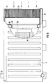
- the separating container 1 is U-shaped or horseshoe-shaped and is mounted on a base plate 17.
- the area 18 of the base plate 17 extending between the two U-legs serves for the arrangement of the drive motor and the Liquid ring pump existing pump unit.
- the first pipe socket 7 forming the inlet of the separating container 1 is provided in the lower region of a U-leg 2.
- the second pipe socket 8 forming the outlet is arranged on the top of the other U-leg. Since the flow connection of the two U-legs takes place solely via the wall part 9 forming the yoke of the U-shaped separating container 1, there is a very long flow path between the two pipe sockets 7 and 8. This is particularly advantageous for soundproofing.
- liquid ring pump 5 is only partially filled with liquid during the standstill, so that restarting is also facilitated here.
- both the separating container 1 and the pump unit 4/5 can already be mounted on the base plate 17 by the manufacturer, a ready-to-use unit is again available which can be set up by the operator of the pump unit without further measures.
- the wall 19 of the opening 10 as an air duct for the fan wheel of the engine cooling fan.
- the wall part 9 as a chamber part connecting the two U-legs 2
- a corresponding depth of this wall part 9 results, so that the opening 10 can perform the function of a guide channel, in particular when the fan wheel 20 is an axial fan wheel.
- a separate fan cover is therefore no longer required for the fan wheel 20.
- Such a cooler 21 can be combined with the pump unit to an operational unit in that the horizontal part 3 of the Separating tank 1 is axially extended beyond the drive motor 4 and the fan 20 arranged on the relevant end face thereof and the cooler 21 is arranged on this extended part 22.
- the fan 20 of the drive motor 4 can simultaneously serve to promote the cooling air required for the cooler 21.
- the cooler 21 can then be inserted between the legs 2 and receives mechanical protection from them.
- the leadership of the cooling air of the cooler 21 can be taken over by the legs 2, in particular in the U-shaped configuration of the separating container 1. If the separating container 1 is then still covered by a cover part resting on the vertical legs 2, a completely closed duct for the cooling air flowing through the cooler 21 is achieved.
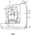
- the vertical leg 2 corresponds functionally to the two vertical legs 2 of the U-shaped separating container 1 and the horizontal leg 3a corresponds to the horizontal U-yoke 3 of the U-shaped separating container 1.
Landscapes
- Engineering & Computer Science (AREA)
- Mechanical Engineering (AREA)
- General Engineering & Computer Science (AREA)
- Structures Of Non-Positive Displacement Pumps (AREA)
- Compressor (AREA)
- Applications Or Details Of Rotary Compressors (AREA)
- Eye Examination Apparatus (AREA)
- Non-Positive Displacement Air Blowers (AREA)
Applications Claiming Priority (2)
| Application Number | Priority Date | Filing Date | Title |
|---|---|---|---|
| DE4417607A DE4417607C1 (de) | 1994-05-19 | 1994-05-19 | Pumpenaggregat |
| DE4417607 | 1994-05-19 |
Publications (3)
| Publication Number | Publication Date |
|---|---|
| EP0683322A2 true EP0683322A2 (fr) | 1995-11-22 |
| EP0683322A3 EP0683322A3 (fr) | 1996-01-31 |
| EP0683322B1 EP0683322B1 (fr) | 1997-08-06 |
Family
ID=6518514
Family Applications (1)
| Application Number | Title | Priority Date | Filing Date |
|---|---|---|---|
| EP95106941A Expired - Lifetime EP0683322B1 (fr) | 1994-05-19 | 1995-05-08 | Dispositif de pompage |
Country Status (5)
| Country | Link |
|---|---|
| US (1) | US5542822A (fr) |
| EP (1) | EP0683322B1 (fr) |
| JP (1) | JP3769047B2 (fr) |
| AT (1) | ATE156571T1 (fr) |
| DE (2) | DE4417607C1 (fr) |
Families Citing this family (15)
| Publication number | Priority date | Publication date | Assignee | Title |
|---|---|---|---|---|
| DE19711591A1 (de) * | 1997-03-20 | 1998-09-24 | Fluidtech Gmbh | Fluidkühlvorrichtung |
| DE19829446A1 (de) * | 1998-07-01 | 2000-01-13 | Siemens Ag | Verdichteraggregat |
| US6405748B1 (en) | 1999-03-22 | 2002-06-18 | David Muhs | Trailer and fuel tank assembly |
| US6390768B1 (en) | 1999-03-22 | 2002-05-21 | David Muhs | Pump impeller and related components |
| US6315524B1 (en) | 1999-03-22 | 2001-11-13 | David Muhs | Pump system with vacuum source |
| US6692234B2 (en) * | 1999-03-22 | 2004-02-17 | Water Management Systems | Pump system with vacuum source |
| DE10040235C2 (de) * | 2000-08-17 | 2003-04-24 | Siemens Ag | Flüssigkeitsringpumpe |
| DE10156180B4 (de) * | 2001-11-15 | 2015-10-15 | Oerlikon Leybold Vacuum Gmbh | Gekühlte Schraubenvakuumpumpe |
| US20040202549A1 (en) * | 2003-01-17 | 2004-10-14 | Barton Russell H. | Liquid ring pump |
| US7878768B2 (en) | 2007-01-19 | 2011-02-01 | David Muhs | Vacuum pump with wear adjustment |
| EP2230406A3 (fr) | 2009-01-31 | 2014-12-03 | Roland Empel | Système de pompe à gaz à anneau liquide doté d'une fondation de machine en matériau de base de type béton |
| US8998586B2 (en) * | 2009-08-24 | 2015-04-07 | David Muhs | Self priming pump assembly with a direct drive vacuum pump |
| US20130000281A1 (en) * | 2011-06-30 | 2013-01-03 | Caterpillar Inc. | Def pump mounted to tank |
| US20130189128A1 (en) * | 2012-01-25 | 2013-07-25 | Compressor Systems, Inc. | Compression system |
| DE202012005755U1 (de) * | 2012-06-12 | 2013-09-16 | Speck Pumpen Vakuumtechnik Gmbh | Pumpenaggregat |
Family Cites Families (11)
| Publication number | Priority date | Publication date | Assignee | Title |
|---|---|---|---|---|
| US1714735A (en) * | 1927-07-18 | 1929-05-28 | Minette E Skidmore | Vacuum and boiler-feed pump |
| DE969928C (de) * | 1953-12-18 | 1958-07-31 | Siemens Ag | Fluessigkeitsring-Saugpumpe |
| DE1293386B (de) * | 1960-05-24 | 1969-04-24 | Becker Gmbh Geb | Drehkolbenverdichter oder -Vakuumpumpe |
| DE2217022C3 (de) * | 1972-04-08 | 1975-03-27 | Sihi Gmbh & Co Kg, 2210 Itzehoe | Flüssigkeitsring-Vakuumpumpe mit Umlaufbehälter |
| DE2460268B2 (de) * | 1974-12-19 | 1977-02-03 | Siemens AG, 1000 Berlin und 8000 München | Fluessigkeitsabscheider |
| NL7606975A (nl) * | 1975-09-22 | 1977-03-24 | Siemens Ag | Vloeistofpompopstelling. |
| CN1005642B (zh) * | 1984-12-07 | 1989-11-01 | 西门子公司 | 真空设备 |
| JPS62291487A (ja) * | 1986-06-10 | 1987-12-18 | Fuji Electric Co Ltd | 水封式ポンプ装置 |
| JPS63186985A (ja) * | 1987-01-29 | 1988-08-02 | Fuji Electric Co Ltd | 水封式ポンプ装置 |
| SU1707249A1 (ru) * | 1990-01-08 | 1992-01-23 | Красноярский инженерно-строительный институт | Жидкостно-кольцева вакуумна установка |
| DE9210277U1 (de) * | 1992-07-31 | 1992-10-15 | Brey, Helmut, 8940 Memmingen | Vakuumanlage |
-
1994
- 1994-05-19 DE DE4417607A patent/DE4417607C1/de not_active Expired - Fee Related
-
1995
- 1995-05-08 EP EP95106941A patent/EP0683322B1/fr not_active Expired - Lifetime
- 1995-05-08 DE DE59500462T patent/DE59500462D1/de not_active Expired - Lifetime
- 1995-05-08 AT AT95106941T patent/ATE156571T1/de not_active IP Right Cessation
- 1995-05-17 JP JP14141095A patent/JP3769047B2/ja not_active Expired - Fee Related
- 1995-05-17 US US08/442,732 patent/US5542822A/en not_active Expired - Lifetime
Also Published As
| Publication number | Publication date |
|---|---|
| ATE156571T1 (de) | 1997-08-15 |
| JP3769047B2 (ja) | 2006-04-19 |
| EP0683322A3 (fr) | 1996-01-31 |
| DE4417607C1 (de) | 1995-10-19 |
| JPH07310688A (ja) | 1995-11-28 |
| DE59500462D1 (de) | 1997-09-11 |
| US5542822A (en) | 1996-08-06 |
| EP0683322B1 (fr) | 1997-08-06 |
Similar Documents
| Publication | Publication Date | Title |
|---|---|---|
| EP0683322B1 (fr) | Dispositif de pompage | |
| DE10248926B4 (de) | Kompressor | |
| DE69620669T2 (de) | Lärmdämpfungsgerät eines Lüfters | |
| EP3298241B1 (fr) | Pompe à vide à palettes lubrifiée à l'huile munie d'un dispositif de séparation et de recyclage de l'huile | |
| DE4401186B4 (de) | Schneidmaschine | |
| DE3445052A1 (de) | Vorrichtung zum entgasen einer mittels eines fluidabscheiders separierten fluessigphase | |
| EP0191153A2 (fr) | Séparateur de fluide, en particulier séparateur gaz/liquide | |
| DE2460268B2 (de) | Fluessigkeitsabscheider | |
| DE102005025665B4 (de) | Luftauslassvorrichtung für eine Motoranordnung sowie Staubsauger mit derselben | |
| DE4304149C1 (de) | Selbstansaugendes Motorpumpenaggregat | |
| DE10337974B4 (de) | Schmiervorrichtung für einen Kolbenverdichter | |
| DE69303447T2 (de) | Vakuumpumpgerät | |
| DE2805015C2 (fr) | ||
| EP0629522A1 (fr) | Système d'alimentation en carburant | |
| DE4421375A1 (de) | Hydraulikaggregat | |
| EP0050770B1 (fr) | Unité de compression enfermée dans une enceinte | |
| DE3031848A1 (de) | Kreiselmaschine, insbesondere radialverdichter | |
| DE19739279A1 (de) | Kompressor-Anlage | |
| EP0284727B1 (fr) | Réservoir d'huile | |
| DE2760023C2 (de) | Verdunstungsluftbefeuchter | |
| DE102008060411A1 (de) | Verbrennungsmotor | |
| DE10212635A1 (de) | Vorrichtung und Verfahren zum Ausleiten von Luft aus einem Fahrzeuggelenkgetriebegehäuse | |
| DE19501352B4 (de) | Brennstoffördereinrichtung mit Strahlpumpenanordnung | |
| DE2401261C3 (fr) | ||
| DE4000126C2 (de) | Vorrichtung zur Belüftung von Kühlschmierflüssigkeit |
Legal Events
| Date | Code | Title | Description |
|---|---|---|---|
| PUAI | Public reference made under article 153(3) epc to a published international application that has entered the european phase |
Free format text: ORIGINAL CODE: 0009012 |
|
| AK | Designated contracting states |
Kind code of ref document: A2 Designated state(s): AT BE CH DE FR GB IT LI NL SE |
|
| PUAL | Search report despatched |
Free format text: ORIGINAL CODE: 0009013 |
|
| AK | Designated contracting states |
Kind code of ref document: A3 Designated state(s): AT BE CH DE FR GB IT LI NL SE |
|
| 17P | Request for examination filed |
Effective date: 19960219 |
|
| GRAG | Despatch of communication of intention to grant |
Free format text: ORIGINAL CODE: EPIDOS AGRA |
|
| 17Q | First examination report despatched |
Effective date: 19960924 |
|
| GRAH | Despatch of communication of intention to grant a patent |
Free format text: ORIGINAL CODE: EPIDOS IGRA |
|
| GRAH | Despatch of communication of intention to grant a patent |
Free format text: ORIGINAL CODE: EPIDOS IGRA |
|
| GRAH | Despatch of communication of intention to grant a patent |
Free format text: ORIGINAL CODE: EPIDOS IGRA |
|
| GRAA | (expected) grant |
Free format text: ORIGINAL CODE: 0009210 |
|
| AK | Designated contracting states |
Kind code of ref document: B1 Designated state(s): AT BE CH DE FR GB IT LI NL SE |
|
| REF | Corresponds to: |
Ref document number: 156571 Country of ref document: AT Date of ref document: 19970815 Kind code of ref document: T |
|
| REG | Reference to a national code |
Ref country code: CH Ref legal event code: NV Representative=s name: SIEMENS SCHWEIZ AG Ref country code: CH Ref legal event code: EP |
|
| GBT | Gb: translation of ep patent filed (gb section 77(6)(a)/1977) |
Effective date: 19970819 |
|
| REF | Corresponds to: |
Ref document number: 59500462 Country of ref document: DE Date of ref document: 19970911 |
|
| ET | Fr: translation filed | ||
| ITF | It: translation for a ep patent filed | ||
| PLBE | No opposition filed within time limit |
Free format text: ORIGINAL CODE: 0009261 |
|
| STAA | Information on the status of an ep patent application or granted ep patent |
Free format text: STATUS: NO OPPOSITION FILED WITHIN TIME LIMIT |
|
| 26N | No opposition filed | ||
| PGFP | Annual fee paid to national office [announced via postgrant information from national office to epo] |
Ref country code: AT Payment date: 19990428 Year of fee payment: 5 |
|
| PGFP | Annual fee paid to national office [announced via postgrant information from national office to epo] |
Ref country code: NL Payment date: 19990518 Year of fee payment: 5 |
|
| PGFP | Annual fee paid to national office [announced via postgrant information from national office to epo] |
Ref country code: SE Payment date: 19990527 Year of fee payment: 5 |
|
| PG25 | Lapsed in a contracting state [announced via postgrant information from national office to epo] |
Ref country code: LI Free format text: LAPSE BECAUSE OF NON-PAYMENT OF DUE FEES Effective date: 19990531 Ref country code: CH Free format text: LAPSE BECAUSE OF NON-PAYMENT OF DUE FEES Effective date: 19990531 |
|
| PGFP | Annual fee paid to national office [announced via postgrant information from national office to epo] |
Ref country code: BE Payment date: 19990601 Year of fee payment: 5 |
|
| REG | Reference to a national code |
Ref country code: CH Ref legal event code: PL |
|
| PG25 | Lapsed in a contracting state [announced via postgrant information from national office to epo] |
Ref country code: AT Free format text: LAPSE BECAUSE OF NON-PAYMENT OF DUE FEES Effective date: 20000508 |
|
| PG25 | Lapsed in a contracting state [announced via postgrant information from national office to epo] |
Ref country code: SE Free format text: LAPSE BECAUSE OF NON-PAYMENT OF DUE FEES Effective date: 20000509 |
|
| PG25 | Lapsed in a contracting state [announced via postgrant information from national office to epo] |
Ref country code: BE Free format text: LAPSE BECAUSE OF NON-PAYMENT OF DUE FEES Effective date: 20000531 |
|
| BERE | Be: lapsed |
Owner name: SIEMENS A.G. Effective date: 20000531 |
|
| PG25 | Lapsed in a contracting state [announced via postgrant information from national office to epo] |
Ref country code: NL Free format text: LAPSE BECAUSE OF NON-PAYMENT OF DUE FEES Effective date: 20001201 |
|
| EUG | Se: european patent has lapsed |
Ref document number: 95106941.8 |
|
| NLV4 | Nl: lapsed or anulled due to non-payment of the annual fee |
Effective date: 20001201 |
|
| REG | Reference to a national code |
Ref country code: GB Ref legal event code: IF02 |
|
| REG | Reference to a national code |
Ref country code: GB Ref legal event code: 732E |
|
| REG | Reference to a national code |
Ref country code: FR Ref legal event code: TP |
|
| PGFP | Annual fee paid to national office [announced via postgrant information from national office to epo] |
Ref country code: GB Payment date: 20130528 Year of fee payment: 19 |
|
| PGFP | Annual fee paid to national office [announced via postgrant information from national office to epo] |
Ref country code: DE Payment date: 20140529 Year of fee payment: 20 Ref country code: FR Payment date: 20140519 Year of fee payment: 20 Ref country code: IT Payment date: 20140526 Year of fee payment: 20 |
|
| GBPC | Gb: european patent ceased through non-payment of renewal fee |
Effective date: 20140508 |
|
| REG | Reference to a national code |
Ref country code: DE Ref legal event code: R071 Ref document number: 59500462 Country of ref document: DE |
|
| PG25 | Lapsed in a contracting state [announced via postgrant information from national office to epo] |
Ref country code: GB Free format text: LAPSE BECAUSE OF NON-PAYMENT OF DUE FEES Effective date: 20140508 |