EP0683373B1 - Echangeur de chaleur et procédé pour sa fabrication - Google Patents
Echangeur de chaleur et procédé pour sa fabrication Download PDFInfo
- Publication number
- EP0683373B1 EP0683373B1 EP95107268A EP95107268A EP0683373B1 EP 0683373 B1 EP0683373 B1 EP 0683373B1 EP 95107268 A EP95107268 A EP 95107268A EP 95107268 A EP95107268 A EP 95107268A EP 0683373 B1 EP0683373 B1 EP 0683373B1
- Authority
- EP
- European Patent Office
- Prior art keywords
- tank
- partition
- bottom wall
- heat exchanger
- upper wall
- Prior art date
- Legal status (The legal status is an assumption and is not a legal conclusion. Google has not performed a legal analysis and makes no representation as to the accuracy of the status listed.)
- Expired - Lifetime
Links
- 238000004519 manufacturing process Methods 0.000 title claims description 7
- 238000005192 partition Methods 0.000 claims description 83
- 238000000034 method Methods 0.000 claims description 11
- 238000005452 bending Methods 0.000 claims 2
- 238000004891 communication Methods 0.000 claims 2
- 239000012530 fluid Substances 0.000 claims 2
- 238000005219 brazing Methods 0.000 description 9
- 238000004378 air conditioning Methods 0.000 description 2
- 238000005520 cutting process Methods 0.000 description 1
- 238000011161 development Methods 0.000 description 1
- 230000018109 developmental process Effects 0.000 description 1
Images




Classifications
-
- F—MECHANICAL ENGINEERING; LIGHTING; HEATING; WEAPONS; BLASTING
- F28—HEAT EXCHANGE IN GENERAL
- F28F—DETAILS OF HEAT-EXCHANGE AND HEAT-TRANSFER APPARATUS, OF GENERAL APPLICATION
- F28F9/00—Casings; Header boxes; Auxiliary supports for elements; Auxiliary members within casings
- F28F9/02—Header boxes; End plates
- F28F9/0202—Header boxes having their inner space divided by partitions
- F28F9/0204—Header boxes having their inner space divided by partitions for elongated header box, e.g. with transversal and longitudinal partitions
- F28F9/0207—Header boxes having their inner space divided by partitions for elongated header box, e.g. with transversal and longitudinal partitions the longitudinal or transversal partitions being separate elements attached to header boxes
-
- B—PERFORMING OPERATIONS; TRANSPORTING
- B21—MECHANICAL METAL-WORKING WITHOUT ESSENTIALLY REMOVING MATERIAL; PUNCHING METAL
- B21D—WORKING OR PROCESSING OF SHEET METAL OR METAL TUBES, RODS OR PROFILES WITHOUT ESSENTIALLY REMOVING MATERIAL; PUNCHING METAL
- B21D53/00—Making other particular articles
- B21D53/02—Making other particular articles heat exchangers or parts thereof, e.g. radiators, condensers fins, headers
-
- F—MECHANICAL ENGINEERING; LIGHTING; HEATING; WEAPONS; BLASTING
- F28—HEAT EXCHANGE IN GENERAL
- F28D—HEAT-EXCHANGE APPARATUS, NOT PROVIDED FOR IN ANOTHER SUBCLASS, IN WHICH THE HEAT-EXCHANGE MEDIA DO NOT COME INTO DIRECT CONTACT
- F28D1/00—Heat-exchange apparatus having stationary conduit assemblies for one heat-exchange medium only, the media being in contact with different sides of the conduit wall, in which the other heat-exchange medium is a large body of fluid, e.g. domestic or motor car radiators
- F28D1/02—Heat-exchange apparatus having stationary conduit assemblies for one heat-exchange medium only, the media being in contact with different sides of the conduit wall, in which the other heat-exchange medium is a large body of fluid, e.g. domestic or motor car radiators with heat-exchange conduits immersed in the body of fluid
- F28D1/04—Heat-exchange apparatus having stationary conduit assemblies for one heat-exchange medium only, the media being in contact with different sides of the conduit wall, in which the other heat-exchange medium is a large body of fluid, e.g. domestic or motor car radiators with heat-exchange conduits immersed in the body of fluid with tubular conduits
- F28D1/053—Heat-exchange apparatus having stationary conduit assemblies for one heat-exchange medium only, the media being in contact with different sides of the conduit wall, in which the other heat-exchange medium is a large body of fluid, e.g. domestic or motor car radiators with heat-exchange conduits immersed in the body of fluid with tubular conduits the conduits being straight
- F28D1/05316—Assemblies of conduits connected to common headers, e.g. core type radiators
- F28D1/05341—Assemblies of conduits connected to common headers, e.g. core type radiators with multiple rows of conduits or with multi-channel conduits combined with a particular flow pattern, e.g. multi-row multi-stage radiators
-
- Y—GENERAL TAGGING OF NEW TECHNOLOGICAL DEVELOPMENTS; GENERAL TAGGING OF CROSS-SECTIONAL TECHNOLOGIES SPANNING OVER SEVERAL SECTIONS OF THE IPC; TECHNICAL SUBJECTS COVERED BY FORMER USPC CROSS-REFERENCE ART COLLECTIONS [XRACs] AND DIGESTS
- Y10—TECHNICAL SUBJECTS COVERED BY FORMER USPC
- Y10S—TECHNICAL SUBJECTS COVERED BY FORMER USPC CROSS-REFERENCE ART COLLECTIONS [XRACs] AND DIGESTS
- Y10S165/00—Heat exchange
- Y10S165/454—Heat exchange having side-by-side conduits structure or conduit section
- Y10S165/471—Plural parallel conduits joined by manifold
- Y10S165/481—Partitions in manifold define serial flow pattern for conduits/conduit groups
- Y10S165/482—Partitions are separate members
-
- Y—GENERAL TAGGING OF NEW TECHNOLOGICAL DEVELOPMENTS; GENERAL TAGGING OF CROSS-SECTIONAL TECHNOLOGIES SPANNING OVER SEVERAL SECTIONS OF THE IPC; TECHNICAL SUBJECTS COVERED BY FORMER USPC CROSS-REFERENCE ART COLLECTIONS [XRACs] AND DIGESTS
- Y10—TECHNICAL SUBJECTS COVERED BY FORMER USPC
- Y10T—TECHNICAL SUBJECTS COVERED BY FORMER US CLASSIFICATION
- Y10T29/00—Metal working
- Y10T29/49—Method of mechanical manufacture
- Y10T29/4935—Heat exchanger or boiler making
- Y10T29/49389—Header or manifold making
Definitions
- This invention relates to a heat exchanger and method for making a heat exchanger for use in an air conditioning system for vehicles, and more particularly, to a heat exchanger that allows for efficient and easy assembly.
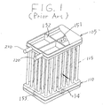
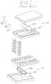
- Figs. 1 and 2 show a conventional heat exchanger used in an air conditioning system, for example, an evaporator or a condenser.
- a heat exchanger comprises an upper tank 105, a lower tank 110 and heat exchanger core 115 disposed between the upper tank and the lower tank.
- the heat exchanger core 115 comprises a plurality of beat transfer tubes disposed parallel to one another.
- the upper tank 105 has an upper wall and a lower wall, which are connected to each other.
- the upper tank 105 is divided into three chambers by first partition plate 151 and second partition plate 152.
- First partition plate 151 and second partition plate 152 include respectively notched portions formed in the centers thereof.
- First partition plate 151 includes a plurality of holes therethrough.
- Lower tank 110 is divided into two chambers, such as first lower chamber and a second lower chamber, by partition plate 153. Further, the lower tank includes preventing overturn plate 154 therein. Preventing overturn plate 154 includes a notched portion formed in the center thereof and a plurality of holes therein. The number of holes formed in preventing overturn plate 154 as well as their respective diameter is determined so that a heat exchanger medium may pass freely through the holes.
- the lower wall of the upper tank 105 and the upper wall of the lower tank 110 are provided with a plurality of connection holes, respectively, for interconnecting a plurality of heat transfer tubes therebetween.
- An inlet pipe 210 and outlet pipe 220 are connected to the upper tank 105.
- first partition plate 151 is placed on the lower wall of the upper tank 105 so as to be located in the center of the lower wall of the upper tank 105 and second partition plate 152 is connected with first partition plate 151 at right angles to each other, so that the notched portion of second partition plate 152 fixedly inserts into the center notched portion of first partition plate 151 in an attempt to prevent movement and overturning during brazing.
- partition plate 153 is placed on the lower wall of the lower tank 110 so as to be located in the center of the lower wall of the lower tank 110.
- preventing overturn plate 154 is connected with partition plate 153 at a right angle, so that the notched portion of partition plate 153 fixedly inserts into the center notched portion of the preventing overturn plate 154 to prevent movement and overturning during brazing.
- the heat exchanger may be placed in a brazing furnace, so that all of its parts may be brazed together.
- the partition plates 151 and 153 tend to fall down until they are connected with their corresponding partition plate 152 or the preventing overturn plate 154 respectively. Further, the partition plates 151, 152 and 153 and the preventing overturn plate 154 tend to incline and move from the desired location unless these parts are formed to extremely precise sizes.
- JP-A-3-260 554 a method of manufacturing a heat exchanger is known wherein temporarily a partition plate is fastened to the interior of a header pipe material having a U-shaped cross-section and being provided with a fitting groove.
- Fig. 1 is a perspective view of a prior art heat exchanger.
- Fig. 2 is an exploded view of the heat exchanger illustrated in Fig. 1.
- Fig. 3 is a plan view of the bottom wall of the top tank in the heat exchanger ellustrated in Fig. 1.
- Fig. 4 is a perspective view of a heat exchanger in accordance with a first embodiment of the present invention.
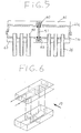
- Fig. 5 is an enlarged sectional view of the heat exchanger illustrated in Fig. 4.
- Fig. 6 is a schematic perspective view of a heat exchanger, showing an example of a heat exchanger medium flow path.
- Fig. 7 is an exploded view of the heat exchange unit illustrated in Fig. 4.
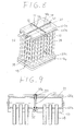
- Fig. 8 is a perspective view of a heat exchanger in accordance with a second embodiment of the present invention.
- Fig. 9 is an enlarged sectional view of the heat exchanger illustrated in Fig. 8.
- Fig. 10 is an exploded view of the heat exchange unit illustrated in Fig. 8.
- Fig. 11 is a perspective view of a heat exchanger in accordance with a third embodiment of the present invention.
- Fig. 12 is an enlarged sectional view of a heat exchanger illustrated in Fig. 11.
- FIG. 4 A heat exchanger in accordance with a first embodiment of the present invention is illustrated in Figs. 4 and 5.
- heat exchanger 20 comprises upper tank 21, lower tank 22 vertically spaced from upper tank 21 and heat exchanger core 23 disposed between upper tank 21 and lower tank 22.
- Heat exchanger core 23 comprise a plurality of heat transfer tubes 24 spaced from one another and disposed in paralleled to one another.
- Upper tank 21 includes upper wall 21a and bottom wall 21b, which are connected so as to form an enclosed tank.
- Upper wall 21a of upper tank 21 includes first concave surface 60 and second concave surface 61 formed inside of upper tank 21 and extending from one horizontal end to other horizontal end.
- First concave surface 60 and second concave surface 61 are formed to be U-shaped in cross section and are vertically projected toward the outside of upper tank 21. Further, first concave surface 60 and second concave surface 61 are formed to intersect each other and to be substantially perpendicular to each other so as to divide upper wall 21a into four areas.
- Bottom wall 21b of upper tank 21 includes third concave surface 62 and fourth concave surface 63 formed inside of upper tank 21.
- Third concave surface 62 and fourth concave surface 63 are formed to be U-shaped in cross section and are vertically projected toward the outside of upper tank 21. Further, third concave surface 62 and fourth concave surface 63 are formed to intersect each other and to be substantially perpendicular to each other so as to divide bottom wall 21b into four areas.
- Upper wall 22a of lower tank 22 includes concave surface 64 formed inside of lower tank 22.
- Bottom wall 22b of lower tank 22 includes concave surface 65 formed inside of lower tank 22.
- Concave surfaces 64 and 65 are formed to be U-shaped in cross section and are vertically projected toward the outside of lower tank 22. Further, concave surfaces 64 and 65 respectively divide upper wall 21a and bottom wall 22b into two areas.
- upper tank 21 includes end plates 21c and 21d respectively covering both ends of the cylindrical opening which are united with upper wall 21a and bottom wall 21b.
- Bottom wall 21b of upper tank 21 and upper wall 22a of lower tank 22 are provided with a plurality of connection holes 40 and 41, respectively, for interconnecting a plurality of heat transfer tubes 24 therebetween
- Upper tank 21 is divided into three chambers, such as first upper chamber 28, second upper chamber 29 and third upper chamber 30 by first partition plate 51 and second partition plate 52.
- Lower tank 22 is divided into two chambers such as first lower chamber 32 and second lower chamber 33, by partition plate 53 which is inserted into concave surfaces 64 and 65.
- Inlet pipe 45 and outlet pipe 46 are connected to upper tank 21.
- a heat exchanger medium may be introduced via inlet pipe 45 into first upper chamber 28 and may flow down through heat transfer tubes 24 until it reaches first lower chamber 32 of lower tank 22. The medium then may flow back into second upper chamber 29 through heat transfer tubes 24. Further, the heat exchanger medium may then flow from second upper chamber 29 of upper tank 21 through heat transfer tubes 24 into second lower chamber 33 of lower tank 22 and then back to third upper chamber 30 through heat transfer tubes 24. When the heat exchanger medium flows through heat transfer tubes 24, heat is exchanged between the exchanger medium and the air flow 17 passing across heat transfer tubes 24.
- first partition plate 51 includes notched portion 51a formed in the center thereof and a plurality of holes 51b therein.
- the plurality of holes 51b are formed with a predetermined number, pitch, and diameter, so that a heat exchanger medium may pass freely through holes 51b of first partition plate 51.
- Upper wall 21a and bottom wall 21b are formed to be U-shaped in cross section.
- Concave surfaces 60, 61, 62 and 63 may be formed by a press work.
- One long end of first partition 51 is inserted into third concave surface 62 of bottom wall 21b of upper tank 21 so as to be positioned in the center of upper tank 21.
- Second partition plate 52 is connected with first partition plate 51 at a right angle so the notched portion 52a of second partition plate 52 fixedly inserts into center notched portion 51a of first partition plate 51. Thereafter, upper wall 21a is placed on bottom wall 21b so that the other ends of partition plate 51 and 52 are respectively inserted into first concave surface 60 and second concave surface 61. Further, first end plate 21c and second end plate 21d are forcibly inserted into the openings which are formed by upper wall 21a and bottom wall 21b.
- partition plate 53 In assembling lower tank 22, one long end of partition plate 53 is inserted into concave surface 65 of bottom wall 22b of lower tank 22 so as to be positioned in the center of lower tank 22. Thereafter, upper wall 22a is placed on bottom wall 22b so that other end of partition plate 53 is inserted into concave surface 64. Further, first end plate 22c and second end plate 22d are forcibly inserted into the openings which are formed by upper wall 22a and bottom wall 22b.
- heat transfer tubes 24 are connected with upper tank 21 and lower tank 22 through connection holes 40 of bottom wall 21b and connection holes 41 of upper wall 22a Finally, assembled heat exchanger 10 may be placed in a brazing furnace, so that all of its parts may be simultaneously brazed together.
- first partition plate 51, second partition plate 52 of upper tank 21, and partition plate 53 of lower tank 53 do not fall down during the assembly process of the tanks. Further, these partition plates do not incline or move from a predetermined place even if the size of the parts, such as partition plates 51, 52, and 53, wall of upper tank 21 and lower tank 22 are not perfectly accurate.
- partition plates 51, 52, and 53 are fixedly and securely connected with upper tank 21 and lower tank 22 by brazing because there is no gap between these partition plates and walls of upper tank 21 and lower tank 22.
- the concave surfaces have a function which prevents the tanks from being deformed by pressure during operation or brazing.
- the heat exchanger of the present invention can be manufactured using a simple process and at a low cost in comparison with the prior art.
- FIGs. 8 and 9 illustrate a second embodiment of the present invention.
- upper wall 121a of upper tank 121 includes a first concave surface 70 and a second concave surface 71 formed inside of upper tank 121.
- the concave surfaces in this embodiment are formed in a box shape.
- First concave surface 70 and second concave surface 71 project toward the outside of upper tank 121 and are formed to be substantially perpendicular to each other so as to divide upper wall 121a into four areas.
- first concave surface 70 and second concave surface 71 include openings 70a and 71a respectively, formed outside of upper tank 121 by cutting out the top ends of concaves 70 and 71.
- Fig. 10 illustrates a method for forming a heat exchanger according to the second embodiment of this invention.
- Upper wall 121a is placed on bottom wall 121b so that they overlap.
- partition plate 51 is inserted into the inside of upper tank 121 through opening 70a.
- One long end of partition plate 51 may then be further inserted into concave 72.
- Second partition plate 52 may be inserted into upper tank 121 through opening 71a and connected with first partition plate 51 at right angles to each other, so that notched portion 52a of second partition plate 52 fixedly inserts into center notched portion 51a of first partition plate 51.
- One long end of partition plate 52 may be further inserted into concave 73 to prevent the movement thereof during brazing.
- partition plate 53 may be inserted into lower tank 122 through opening 74a. Partition plate is then further inserted into concave 75.
- substantially the same advantages as those in the first embodiment can be obtained.
- Figs. 11 and 12 illustrate a third embodiment of the present invention.
- upper wall 21a of upper tank 21 does not include a concave surface inside of upper tank 21.
- bottom wall 21b of upper tank 21 includes a first concave surface 62 and second concave surface 63 vertically projecting toward the outside of upper tank 21 and formed to intersect and be substantially perpendicular to each other so as to divide bottom wall 21b into four areas.
- upper wall 22a of lower tank 22 does not include a concave surface.
- Bottom wall 22b of lower tank 22 includes concave surface 65 formed inside of lower tank 22. Concave surface 65 is formed to be U-shaped in cross section and vertically projects toward the outside of lower tank 22. Further, concave surface 65 divides bottom wall 22b of lower tank 22 into two areas.
Landscapes
- Engineering & Computer Science (AREA)
- Mechanical Engineering (AREA)
- Physics & Mathematics (AREA)
- Thermal Sciences (AREA)
- General Engineering & Computer Science (AREA)
- Heat-Exchange Devices With Radiators And Conduit Assemblies (AREA)
Claims (9)
- Echangeur de chaleur comprenant :caractérisé en ce que lesdites parties concaves (60, 61, 62, 63 ; 70, 71, 72, 73) dudit premier réservoir (21) sont sensiblement en forme de croix et lesdites parties concaves (64, 65 ; 74, 75) dudit second réservoir (22) sont sensiblement de forme linéaire.un premier réservoir (21) comprenant une pluralité de trous de raccordement (40), une première cloison (51) et une deuxième cloison (52) disposées à l'intérieur de celui-ci pour diviser ledit premier réservoir (21) en un premier nombre de chambres, ledit premier réservoir (21) comprenant respectivement un orifice d'admission (45) afin de permettre à un milieu de transfert de chaleur de pénétrer dans ledit échangeur de chaleur et un orifice de sortie (46) afin de permettre à un milieu de transfert de chaleur de sortir dudit échangeur de chaleur ;un second réservoir (22) espacé dudit premier réservoir (21) et comprenant une pluralité de trous de raccordement (41), et une troisième cloison (53) disposée à l'intérieur de celui-ci pour diviser ledit second réservoir (22) en un second nombre de chambres ;une pluralité de tubes de transfert de chaleur (24) disposés de manière fixe entre ledit premier réservoir (21) et ledit second réservoir (22) en communication fluidique ;ledit premier réservoir (21) comprenant des parties concaves (60, 61, 62, 63) formées horizontalement sur une paroi supérieure (21a) et sur une paroi inférieure (21b) dudit premier réservoir (21), les extrémités de ladite première cloison (51) et ladite deuxième cloison (52) s'insérant respectivement dans lesdites parties concaves (60, 61, 62, 63 ; 70, 71, 72, 73) afin d'empêcher le renversement de ladite première cloison (51) et de ladite deuxième cloison (52) pendant l'assemblage dudit premier réservoir (21), ledit second réservoir (22) comprenant des parties concaves (64, 65 ; 74, 75) formées horizontalement sur une paroi supérieure (22a) et une paroi inférieure (22b) de celui-ci, les extrémités de ladite troisième cloison (53) s'insérant dans lesdites parties concaves (64, 65 ; 74, 75) afin d'empêcher le renversement de ladite troisième cloison (53) pendant l'assemblage dudit second réservoir (22) ;
- Echangeur de chaleur selon la revendication 1, dans lequel ledit second nombre de chambres est inférieur d'une unité audit premier nombre de chambres.
- Echangeur de chaleur selon la revendication 1 ou 2, dans lequel ladite pluralité de trous de raccordement (40, 41) est alignée en rangées.
- Echangeur de chaleur selon l'une des revendications 1 à 3, dans lequel lesdites parties concaves dudit premier réservoir (21) et dudit second réservoir (22) sont conformées sensiblement avec une section transversale en forme de U.
- Echangeur de chaleur selon la revendication 1, dans lequel lesdites parties concaves dudit premier réservoir et dudit second réservoir comprennent respectivement des parties supérieures formées pour être ouvertes à l'extérieur de ceux-ci.
- Procédé de fabrication d'un échangeur de chaleur selon la revendication 1, comprenant les étapes consistant à :cintrer une pluralité de plaques brutes planes afin d'avoir des coupes transversales en forme de U définissant une partie plate et des parties de bride s'étendant aux deux extrémités de ladite partie plate en tant que paroi supérieure (21a, 22a) et une partie inférieure (21b, 22b) dudit premier réservoir (21) et dudit second réservoir (22) ;percer une pluralité de trous de raccordement (40, 41) sur ladite partie plate de ladite paroi inférieure (21b) dudit premier réservoir (21) et de ladite paroi supérieure (22a) dudit second réservoir (22) ;former des parties concaves (60, 61, 62, 63) sur ladite partie plate de ladite paroi supérieure (21a) et de ladite paroi inférieure (21b) dudit premier réservoir sensiblement en forme de croix ;insérer une extrémité de ladite première cloison (51) dans une partie concave (62) de ladite paroi inférieure (21b) dudit premier réservoir (21) et insérer une extrémité de ladite deuxième cloison (52) dans une partie concave (63) de ladite paroi inférieure (21b) dudit premier réservoir (21) de sorte que ladite deuxième paroi (52) est sensiblement perpendiculaire à ladite première cloison (51) ;placer ladite paroi supérieure (21a) dudit premier réservoir (21) sur ladite paroi inférieure (21b) dudit premier réservoir (21) de manière que ladite paroi inférieure (21b) dudit premier réservoir (21) soit recouverte par ladite paroi supérieure (21a), et que les autres extrémités de ladite première cloison (51) et de ladite seconde cloison (52) s'insèrent dans lesdites parties concaves (60, 61) de ladite paroi supérieure (21a) et de ladite paroi inférieure (21b) dudit premier réservoir (21) ;insérer une extrémité de ladite troisième cloison (53) dans la partie concave linéaire (65) de ladite paroi inférieure (22b) dudit second réservoir (22) ;placer ladite paroi supérieure (22a) dudit second réservoir (22) sur ladite paroi inférieure (22b) dudit second réservoir (22), de manière que ladite paroi inférieure (22b) dudit second réservoir (22) soit récouverte par ladite paroi supérieure (22a), et que l'autre extrémité de ladite troisième cloison (53) s'insère dans les parties concaves linéaires (64) de ladite paroi supérieure (22a) et de ladite paroi inférieure (22b) dudit réservoir inférieur (22) ; etinsérer les extrémités opposées desdits tubes de transfert de chaleur (24) dans les trous de raccordement respectifs (40, 41) dudit premier réservoir (21) et dudit second réservoir (22).
- Procédé selon la revendication 6, dans lequel ledit second nombre de chambres est inférieur d'une unité audit premier nombre de chambres.
- Procédé de fabrication d'un échangeur de chaleur selon la revendication 1, comprenant les étapes consistant à :cintrer une pluralité de plaques brutes planes afin d'obtenir une coupe transversale en forme de U définissant une partie plate et des parties de bride s'étendant aux deux extrémités de ladite partie plate en tant que paroi supérieure (121a, 122a) et une paroi inférieure (121b, 122b) dudit premier réservoir (121) et dudit second réservoir (122) ;percer une pluralité de trous de raccordement (40, 41) dans ladite partie plate de ladite paroi inférieure (121b) dudit premier réservoir (121) et de ladite paroi supérieure (122a) dudit second réservoir (122) ;former des parties concaves (70 à 73) dans ladite partie plate de ladite paroi supérieure (121a) et de ladite paroi inférieure (121b) dudit premier réservoir (121) sensiblement en forme de croix ;former des ouvertures (70a, 71a) sur le dessus de ladite partie concave (70, 71) ;placer ladite paroi supérieure (121a) dudit premier réservoir (121) sur ladite paroi inférieure (121b) dudit premier réservoir (121) de manière que ladite paroi inférieure (221b) dudit premier réservoir (121) soit recouverte ladite paroi supérieure (121a) ;insérer une extrémité de ladite première cloison (51) dans ladite partie concave (72) de ladite paroi inférieure (121b) dudit premier réservoir (121) à travers ladite ouverture (70a) ;insérer une deuxième cloison (52) dans ladite partie concave (73) de ladite paroi inférieure (121b) à travers ladite ouverture (71a) de manière que la deuxième cloison (52) soit sensiblement perpendiculaire à ladite première cloison (51) ;former des parties concaves linéaires (74, 75) sur ladite partie plate de ladite paroi supérieure (122a) et sur ladite paroi inférieure (122b) dudit second réservoir (122) ;former une ouverture (74a) sur le dessus de ladite partie concave (74) ;placer ladite paroi supérieure (122a) dudit second réservoir (122) sur ladite paroi inférieure (122b) dudit second réservoir (122) de manière que ladite paroi inférieure (122b) dudit second réservoir (122) soit recouverte par ladite paroi supérieure (122a) ;insérer une extrémité de ladite troisième cloison (53) dans ladite partie concave (75) de ladite paroi inférieure (122b) dudit second réservoir (122) à travers ladite ouverture (74a) ; etinsérer les extrémités desdits tubes de transfert de chaleur (24) dans lesdits trous de raccordement respectifs (40, 41) dudit premier réservoir (121) et dudit second réservoir (122).
- Echangeur de chaleur comprenant :caractérisé en ce queun premier réservoir (21) comprenant une pluralité de trous de raccordement (40), une première cloison (51) et une deuxième cloison (52) disposées à l'intérieur de celui-ci afin de le diviser en un premier nombre de chambres, ledit premier réservoir (21) comprenant respectivement un orifice d'admission (45) afin de permettre à un milieu de transfert de chaleur de pénétrer dans ledit échangeur de chaleur et un orifice de sortie (46) afin de permettre au milieu de transfert de chaleur de sortir dudit échangeur de chaleur ;un second réservoir (22) espacé dudit premier réservoir (21) et comprenant une pluralité de trous de raccordement (41) et une troisième cloison (53) disposée à l'intérieur de celui-ci afin de diviser ledit second réservoir (22) en un second nombre de chambres ;une pluralité de tubes de. transfert de chaleur (24) disposés de manière fixe entre ledit premier réservoir (21) et ledit second réservoir (22) en communication fluidique ;ledit premier réservoir (21) comprenant une première partie concave (62) et une seconde partie concave (63) formées horizontalement sur une paroi inférieure (21b) dudit premier réservoir (21) et faisant saillie verticalement vers l'extérieur du réservoir supérieur (21), les extrémités de ladite première cloison (51) et de ladite deuxième cloison (52) s'insérant respectivement dans lesdites parties concaves (62, 63) afin d'empêcher le renversement de ladite première cloison (51) et de ladite deuxième cloison (52) pendant l'assemblage dudit premier réservoir (21), ledit second réservoir (22) comprenant une partie concave (65) ayant une coupe transversale en forme de U formée horizontalement sur une paroi inférieure (22b) de celui-ci et faisant saillie verticalement à l'extérieur du réservoir inférieur (22), les extrémités de ladite troisième cloison (53) s'insérant dans ladite partie concave (65) afin d'empêcher le renversement de ladite troisième cloison (53) pendant l'assemblage dudit second réservoir (22) ;lesdites parties concaves (62, 63) dudit premier réservoir (21) sont sensiblement en forme de croix et ladite partie concave (65) dudit second réservoir (22) est sensiblement de forme linéaire.
Applications Claiming Priority (2)
| Application Number | Priority Date | Filing Date | Title |
|---|---|---|---|
| JP6124690A JPH07305990A (ja) | 1994-05-16 | 1994-05-16 | 多管式熱交換器 |
| JP124690/94 | 1994-05-16 |
Publications (2)
| Publication Number | Publication Date |
|---|---|
| EP0683373A1 EP0683373A1 (fr) | 1995-11-22 |
| EP0683373B1 true EP0683373B1 (fr) | 1998-08-12 |
Family
ID=14891684
Family Applications (1)
| Application Number | Title | Priority Date | Filing Date |
|---|---|---|---|
| EP95107268A Expired - Lifetime EP0683373B1 (fr) | 1994-05-16 | 1995-05-12 | Echangeur de chaleur et procédé pour sa fabrication |
Country Status (4)
| Country | Link |
|---|---|
| US (1) | US5582239A (fr) |
| EP (1) | EP0683373B1 (fr) |
| JP (1) | JPH07305990A (fr) |
| DE (1) | DE69503966T2 (fr) |
Families Citing this family (62)
| Publication number | Priority date | Publication date | Assignee | Title |
|---|---|---|---|---|
| KR0165067B1 (ko) * | 1996-04-09 | 1999-01-15 | 구자홍 | 2열 플랫튜브형 열교환기 |
| DE19719251C2 (de) * | 1997-05-07 | 2002-09-26 | Valeo Klimatech Gmbh & Co Kg | Verteil-/Sammel-Kasten eines mindestens zweiflutigen Verdampfers einer Kraftfahrzeugklimaanlage |
| US5941303A (en) * | 1997-11-04 | 1999-08-24 | Thermal Components | Extruded manifold with multiple passages and cross-counterflow heat exchanger incorporating same |
| JPH11287587A (ja) * | 1998-04-03 | 1999-10-19 | Denso Corp | 冷媒蒸発器 |
| DE19819247A1 (de) * | 1998-04-29 | 1999-11-11 | Valeo Klimatech Gmbh & Co Kg | Wärmetauscher für Kraftfahrzeuge, insbesondere Wasser/Luft-Wärmetauscher oder Verdampfer |
| DE19825561A1 (de) | 1998-06-08 | 1999-12-09 | Valeo Klimatech Gmbh & Co Kg | Wärmetauscher mit verrippten Flachrohren, insbesondere Heizungswärmetauscher, Motorkühler, Verflüssiger oder Verdampfer, für Kraftfahrzeuge |
| US6742256B2 (en) | 1998-12-08 | 2004-06-01 | Honeywell International Inc. | Method and apparatus for flexible construction of heat exchanger tanks |
| JP2000304488A (ja) | 1999-04-23 | 2000-11-02 | Calsonic Kansei Corp | アルミニウム合金製熱交換器 |
| US6449979B1 (en) | 1999-07-02 | 2002-09-17 | Denso Corporation | Refrigerant evaporator with refrigerant distribution |
| US6289585B1 (en) | 2000-03-10 | 2001-09-18 | Adrian Staruszkiewicz | Method of attaching pipes |
| JP4094806B2 (ja) * | 2000-12-28 | 2008-06-04 | カルソニックカンセイ株式会社 | 熱交換器の製造方法 |
| US6745827B2 (en) * | 2001-09-29 | 2004-06-08 | Halla Climate Control Corporation | Heat exchanger |
| KR100825708B1 (ko) * | 2001-09-29 | 2008-04-29 | 한라공조주식회사 | 이산화탄소용 열교환기 |
| CN100368752C (zh) * | 2001-12-21 | 2008-02-13 | 贝洱两合公司 | 用于汽车的热交换器 |
| DE10237648A1 (de) * | 2002-08-13 | 2004-02-26 | Behr Gmbh & Co. | Wärmeübertrager |
| EP1577628A4 (fr) * | 2002-12-12 | 2006-06-07 | Zexel Valeo Climate Contr Corp | Reservoir pour echangeur de chaleur |
| JP4124136B2 (ja) * | 2003-04-21 | 2008-07-23 | 株式会社デンソー | 冷媒蒸発器 |
| DE102004003789A1 (de) * | 2004-01-23 | 2005-08-18 | Behr Gmbh & Co. Kg | Wärmetauscher |
| JP4653803B2 (ja) * | 2004-03-05 | 2011-03-16 | ベール ゲーエムベーハー ウント コー カーゲー | 熱を交換する装置およびそれを形成する方法 |
| KR100590658B1 (ko) * | 2004-04-28 | 2006-06-19 | 모딘코리아 유한회사 | 자동차용 증발기의 헤더 파이프 |
| CN100585320C (zh) * | 2004-07-16 | 2010-01-27 | 贝洱两合公司 | 热交换器,为热交换器容纳流体的箱以及制造这种箱的方法 |
| CN100499090C (zh) * | 2004-07-31 | 2009-06-10 | 鸿富锦精密工业(深圳)有限公司 | 液冷式散热装置 |
| DE102004056790A1 (de) * | 2004-10-04 | 2006-04-06 | Behr Gmbh & Co. Kg | Wärmetauscher |
| US7275394B2 (en) * | 2005-04-22 | 2007-10-02 | Visteon Global Technologies, Inc. | Heat exchanger having a distributer plate |
| US20070051504A1 (en) * | 2005-09-06 | 2007-03-08 | Showa Denko K.K. | Heat exchanger |
| DE102006016341A1 (de) * | 2006-04-05 | 2007-10-11 | Behr Gmbh & Co. Kg | Wärmeübertrager |
| ES2387134T3 (es) * | 2006-10-13 | 2012-09-14 | Carrier Corporation | Intercambiadores de calor multipasos que tienen colectores de retorno con insertos de distribución |
| US20080185134A1 (en) * | 2007-02-07 | 2008-08-07 | Hoehne Mark R | Two-piece header/manifold construction for a heat exchanger having flattened tubes |
| CN201059823Y (zh) * | 2007-06-19 | 2008-05-14 | 上海双桦汽车零部件股份有限公司 | 平行流蒸发器 |
| KR101372303B1 (ko) * | 2007-08-09 | 2014-03-11 | 한라비스테온공조 주식회사 | 열교환기 |
| JP4881276B2 (ja) * | 2007-10-19 | 2012-02-22 | 株式会社ティラド | 熱交換器の製造方法および熱交換器 |
| US8353330B2 (en) * | 2007-11-02 | 2013-01-15 | Halla Climate Control Corp. | Heat exchanger |
| WO2009061157A2 (fr) * | 2007-11-09 | 2009-05-14 | Halla Climate Control Corp. | Échangeur de chaleur |
| CN101910775B (zh) | 2007-11-09 | 2012-10-17 | 汉拏空调株式会社 | 热交换器 |
| US20100147501A1 (en) * | 2008-12-15 | 2010-06-17 | Delphi Technologies, Inc. | Curled manifold for evaporator |
| US8851158B2 (en) | 2009-02-17 | 2014-10-07 | Hamilton Sundstrand Corporation | Multi-chamber heat exchanger header and method of making |
| WO2015142615A1 (fr) | 2014-03-18 | 2015-09-24 | Carrier Corporation | Évaporateur d'échangeur de chaleur à micro-canaux |
| US20110005719A1 (en) * | 2009-07-10 | 2011-01-13 | Keihin Corporation | Heat exchanger for vehicular air conditioning apparatus |
| DE102010003631A1 (de) * | 2010-04-01 | 2011-10-06 | Behr Gmbh & Co. Kg | Verfahren zur Herstellung eines Metallteils |
| JP5651991B2 (ja) | 2010-05-10 | 2015-01-14 | 富士通株式会社 | ラジエータ及びそれを備えた電子機器 |
| TWI551803B (zh) | 2010-06-15 | 2016-10-01 | 拜歐菲樂Ip有限責任公司 | 低溫熱力閥裝置、含有該低溫熱力閥裝置之系統及使用該低溫熱力閥裝置之方法 |
| KR101786965B1 (ko) * | 2010-10-28 | 2017-11-15 | 삼성전자주식회사 | 헤더유닛 및 이를 가지는 열교환기 |
| CN102818471A (zh) * | 2011-06-09 | 2012-12-12 | 张荣伟 | 钢三柱一体插接式片头 |
| JP5852811B2 (ja) * | 2011-08-26 | 2016-02-03 | 株式会社ケーヒン・サーマル・テクノロジー | 熱交換器 |
| TWI575062B (zh) | 2011-12-16 | 2017-03-21 | 拜歐菲樂Ip有限責任公司 | 低溫注射組成物,用於低溫調節導管中流量之系統及方法 |
| US9222734B2 (en) * | 2012-01-03 | 2015-12-29 | Denso International America, Inc. | Heat exchanger tank groove geometry |
| JP6075956B2 (ja) * | 2012-01-31 | 2017-02-08 | 株式会社ケーヒン・サーマル・テクノロジー | エバポレータ |
| JP6088905B2 (ja) * | 2013-05-24 | 2017-03-01 | サンデンホールディングス株式会社 | 複式熱交換器 |
| WO2015010853A1 (fr) * | 2013-07-25 | 2015-01-29 | Jaeggi Hybridtechnologie Ag | Tube collecteur pour dispositif échangeur de chaleur, dispositif échangeur de chaleur et procédé de purge d'un dispositif échangeur de chaleur |
| MX2016003270A (es) | 2013-09-13 | 2016-10-26 | Biofilm Ip Llc | Valvulas magneto-criogenicas, sistemas y metodos para modular flujo en un conducto. |
| FR3013436B1 (fr) * | 2013-11-18 | 2018-12-07 | Valeo Systemes Thermiques | Collecteur pour echangeur de chaleur |
| DE102015010288A1 (de) | 2014-08-22 | 2016-02-25 | Modine Manufacturing Company | Wärmetauscher, Behälter für Wärmetauscher und Verfahren zur Herstellung desselben |
| KR102622735B1 (ko) * | 2016-09-13 | 2024-01-09 | 삼성전자주식회사 | 열교환기 |
| IL248304B (en) * | 2016-10-10 | 2021-07-29 | Magen Eco Energy A C S Ltd | Heat exchanger and its module |
| JP6369648B1 (ja) | 2017-03-27 | 2018-08-08 | ダイキン工業株式会社 | 熱交換器および空気調和装置 |
| WO2018181338A1 (fr) * | 2017-03-27 | 2018-10-04 | ダイキン工業株式会社 | Échangeur de chaleur et dispositif de climatisation |
| US11415375B2 (en) * | 2018-02-12 | 2022-08-16 | Mahle International Gmbh | Thermal component, method for producing same, and heat exchanger |
| CN108759535B (zh) * | 2018-03-19 | 2020-09-01 | 天津科技大学 | 一种模块式相变储能换热器 |
| TWI677659B (zh) * | 2019-01-16 | 2019-11-21 | 萬在工業股份有限公司 | 並聯式冷凝裝置 |
| KR102833395B1 (ko) * | 2021-02-02 | 2025-07-11 | 한온시스템 주식회사 | 열교환기의 헤더탱크 |
| US11737246B2 (en) * | 2021-04-27 | 2023-08-22 | Quanta Computer Inc. | Dual-radiator cooling device |
| WO2023121302A1 (fr) * | 2021-12-22 | 2023-06-29 | 한온시스템 주식회사 | Échangeur de chaleur |
Family Cites Families (12)
| Publication number | Priority date | Publication date | Assignee | Title |
|---|---|---|---|---|
| US3835920A (en) * | 1972-02-22 | 1974-09-17 | Gen Motors Corp | Compact fluid heat exchanger |
| JPS59229195A (ja) * | 1984-05-18 | 1984-12-22 | Matsushita Refrig Co | 熱交換器 |
| DE3918312A1 (de) * | 1988-12-22 | 1990-12-06 | Thermal Waerme Kaelte Klima | Flachrohrverfluessiger, herstellungsverfahren und anwendung |
| JPH02103666U (fr) * | 1989-02-02 | 1990-08-17 | ||
| JP2513997Y2 (ja) * | 1989-04-11 | 1996-10-09 | サンデン株式会社 | ヘッダパイプ |
| JP2790890B2 (ja) * | 1990-03-07 | 1998-08-27 | サンデン株式会社 | 熱交換器用ヘッダーパイプの製造方法 |
| JPH0729416Y2 (ja) * | 1990-04-05 | 1995-07-05 | 株式会社ゼクセル | 熱交換器のタンク部仕切り装置 |
| CA2036494C (fr) * | 1990-05-11 | 1995-06-27 | Tai W. Kwok | Echange de chaleur pour procede d'alkylation |
| JPH04225796A (ja) * | 1990-12-27 | 1992-08-14 | Nippondenso Co Ltd | 熱交換器用タンク |
| DE4137037A1 (de) * | 1991-07-02 | 1993-01-14 | Thermal Waerme Kaelte Klima | Sammler fuer einen flachrohrverfluessiger |
| JPH0731030B2 (ja) * | 1991-12-20 | 1995-04-10 | サンデン株式会社 | 熱交換器用ヘッダ−パイプの仕切板組付構造及び組付方法 |
| US5329995A (en) * | 1992-08-28 | 1994-07-19 | Valeo Engine Cooling Incorporated | Heat exchanger assembly I |
-
1994
- 1994-05-16 JP JP6124690A patent/JPH07305990A/ja active Pending
-
1995
- 1995-05-12 DE DE69503966T patent/DE69503966T2/de not_active Expired - Fee Related
- 1995-05-12 EP EP95107268A patent/EP0683373B1/fr not_active Expired - Lifetime
- 1995-05-15 US US08/441,417 patent/US5582239A/en not_active Expired - Fee Related
Also Published As
| Publication number | Publication date |
|---|---|
| US5582239A (en) | 1996-12-10 |
| EP0683373A1 (fr) | 1995-11-22 |
| DE69503966D1 (de) | 1998-09-17 |
| DE69503966T2 (de) | 1999-01-14 |
| JPH07305990A (ja) | 1995-11-21 |
Similar Documents
| Publication | Publication Date | Title |
|---|---|---|
| US5582239A (en) | Heat exchanger and method of making same | |
| EP0660063B1 (fr) | Echangeur de chaleur | |
| EP0807794B1 (fr) | Echangeurs de chaleur à plaques | |
| US5417280A (en) | Stacked heat exchanger and method of manufacturing the same | |
| US4960169A (en) | Baffle for tubular heat exchanger header | |
| US5517757A (en) | Method of manufacturing a stacked heat exchanger | |
| AU668403B2 (en) | Stacked heat exchanger | |
| EP1012523B1 (fr) | Supports de fixation alveoles et etages pour echangeurs de chaleur | |
| EP1167911B1 (fr) | Evaporateur | |
| US6073688A (en) | Flat tubes for heat exchanger | |
| EP0622599B1 (fr) | Echangeur de chaleur | |
| EP0584994B1 (fr) | Echangeur de chaleur | |
| EP3301394B1 (fr) | Échangeur de chaleur, son collecteur et son procédé de fabrication | |
| EP0640804A1 (fr) | Echangeur de chaleur et arrangement de tubes pour cela | |
| JPH04177094A (ja) | 積層型熱交換器 | |
| EP0704666B1 (fr) | Echangeur de chaleur | |
| US4775006A (en) | Heat exchanger, particularly a coolant evaporator | |
| US6142217A (en) | Motor vehicle flat tube heat exchanger with flat tubes retained on collars of a tube bottom | |
| EP0657711B1 (fr) | Echangeur de chaleur | |
| EP0745821B1 (fr) | Procédé de fabrication d'un échangeur de chaleur avec collecteur compartimenté | |
| KR0146488B1 (ko) | 적층형 열교환기 | |
| EP0797067B1 (fr) | Procédé pour la fabrication d'un dispositif pour la distribution uniforme du fluide vers une pluralité de tubes d'un échangeur de chaleur | |
| JPH1163881A (ja) | 積層型熱交換器 | |
| EP0601622A2 (fr) | Evaporateurs à écoulement en épingle pour des systèmes de climatisation de véhicule | |
| JPH04335996A (ja) | 熱交換器 |
Legal Events
| Date | Code | Title | Description |
|---|---|---|---|
| PUAI | Public reference made under article 153(3) epc to a published international application that has entered the european phase |
Free format text: ORIGINAL CODE: 0009012 |
|
| AK | Designated contracting states |
Kind code of ref document: A1 Designated state(s): DE FR GB IT SE |
|
| 17P | Request for examination filed |
Effective date: 19951107 |
|
| 17Q | First examination report despatched |
Effective date: 19961219 |
|
| GRAG | Despatch of communication of intention to grant |
Free format text: ORIGINAL CODE: EPIDOS AGRA |
|
| GRAG | Despatch of communication of intention to grant |
Free format text: ORIGINAL CODE: EPIDOS AGRA |
|
| GRAG | Despatch of communication of intention to grant |
Free format text: ORIGINAL CODE: EPIDOS AGRA |
|
| GRAH | Despatch of communication of intention to grant a patent |
Free format text: ORIGINAL CODE: EPIDOS IGRA |
|
| GRAH | Despatch of communication of intention to grant a patent |
Free format text: ORIGINAL CODE: EPIDOS IGRA |
|
| GRAH | Despatch of communication of intention to grant a patent |
Free format text: ORIGINAL CODE: EPIDOS IGRA |
|
| GRAH | Despatch of communication of intention to grant a patent |
Free format text: ORIGINAL CODE: EPIDOS IGRA |
|
| GRAA | (expected) grant |
Free format text: ORIGINAL CODE: 0009210 |
|
| AK | Designated contracting states |
Kind code of ref document: B1 Designated state(s): DE FR GB IT SE |
|
| ITF | It: translation for a ep patent filed | ||
| REF | Corresponds to: |
Ref document number: 69503966 Country of ref document: DE Date of ref document: 19980917 |
|
| ET | Fr: translation filed | ||
| PGFP | Annual fee paid to national office [announced via postgrant information from national office to epo] |
Ref country code: SE Payment date: 19990414 Year of fee payment: 5 |
|
| PGFP | Annual fee paid to national office [announced via postgrant information from national office to epo] |
Ref country code: FR Payment date: 19990511 Year of fee payment: 5 |
|
| PGFP | Annual fee paid to national office [announced via postgrant information from national office to epo] |
Ref country code: GB Payment date: 19990512 Year of fee payment: 5 |
|
| PGFP | Annual fee paid to national office [announced via postgrant information from national office to epo] |
Ref country code: DE Payment date: 19990514 Year of fee payment: 5 |
|
| PLBE | No opposition filed within time limit |
Free format text: ORIGINAL CODE: 0009261 |
|
| STAA | Information on the status of an ep patent application or granted ep patent |
Free format text: STATUS: NO OPPOSITION FILED WITHIN TIME LIMIT |
|
| 26N | No opposition filed | ||
| PG25 | Lapsed in a contracting state [announced via postgrant information from national office to epo] |
Ref country code: GB Free format text: LAPSE BECAUSE OF NON-PAYMENT OF DUE FEES Effective date: 20000512 |
|
| PG25 | Lapsed in a contracting state [announced via postgrant information from national office to epo] |
Ref country code: SE Free format text: LAPSE BECAUSE OF NON-PAYMENT OF DUE FEES Effective date: 20000513 |
|
| GBPC | Gb: european patent ceased through non-payment of renewal fee |
Effective date: 20000512 |
|
| EUG | Se: european patent has lapsed |
Ref document number: 95107268.5 |
|
| PG25 | Lapsed in a contracting state [announced via postgrant information from national office to epo] |
Ref country code: FR Free format text: LAPSE BECAUSE OF NON-PAYMENT OF DUE FEES Effective date: 20010131 |
|
| PG25 | Lapsed in a contracting state [announced via postgrant information from national office to epo] |
Ref country code: DE Free format text: LAPSE BECAUSE OF NON-PAYMENT OF DUE FEES Effective date: 20010301 |
|
| REG | Reference to a national code |
Ref country code: FR Ref legal event code: ST |
|
| PG25 | Lapsed in a contracting state [announced via postgrant information from national office to epo] |
Ref country code: IT Free format text: LAPSE BECAUSE OF NON-PAYMENT OF DUE FEES;WARNING: LAPSES OF ITALIAN PATENTS WITH EFFECTIVE DATE BEFORE 2007 MAY HAVE OCCURRED AT ANY TIME BEFORE 2007. THE CORRECT EFFECTIVE DATE MAY BE DIFFERENT FROM THE ONE RECORDED. Effective date: 20050512 |