EP0685592B1 - Stahldraht-Litzenseil - Google Patents
Stahldraht-Litzenseil Download PDFInfo
- Publication number
- EP0685592B1 EP0685592B1 EP95810339A EP95810339A EP0685592B1 EP 0685592 B1 EP0685592 B1 EP 0685592B1 EP 95810339 A EP95810339 A EP 95810339A EP 95810339 A EP95810339 A EP 95810339A EP 0685592 B1 EP0685592 B1 EP 0685592B1
- Authority
- EP
- European Patent Office
- Prior art keywords
- rope
- wire rope
- steel wire
- cross
- base portions
- Prior art date
- Legal status (The legal status is an assumption and is not a legal conclusion. Google has not performed a legal analysis and makes no representation as to the accuracy of the status listed.)
- Expired - Lifetime
Links
Images

Classifications
-
- D—TEXTILES; PAPER
- D07—ROPES; CABLES OTHER THAN ELECTRIC
- D07B—ROPES OR CABLES IN GENERAL
- D07B1/00—Constructional features of ropes or cables
- D07B1/16—Ropes or cables with an enveloping sheathing or inlays of rubber or plastics
- D07B1/165—Ropes or cables with an enveloping sheathing or inlays of rubber or plastics characterised by a plastic or rubber inlay
- D07B1/167—Ropes or cables with an enveloping sheathing or inlays of rubber or plastics characterised by a plastic or rubber inlay having a predetermined shape
-
- D—TEXTILES; PAPER
- D07—ROPES; CABLES OTHER THAN ELECTRIC
- D07B—ROPES OR CABLES IN GENERAL
- D07B2201/00—Ropes or cables
- D07B2201/20—Rope or cable components
- D07B2201/2047—Cores
- D07B2201/2048—Cores characterised by their cross-sectional shape
- D07B2201/2049—Cores characterised by their cross-sectional shape having protrusions extending radially functioning as spacer between strands or wires
-
- D—TEXTILES; PAPER
- D07—ROPES; CABLES OTHER THAN ELECTRIC
- D07B—ROPES OR CABLES IN GENERAL
- D07B2201/00—Ropes or cables
- D07B2201/20—Rope or cable components
- D07B2201/2071—Spacers
- D07B2201/2073—Spacers in circumferencial direction
-
- D—TEXTILES; PAPER
- D07—ROPES; CABLES OTHER THAN ELECTRIC
- D07B—ROPES OR CABLES IN GENERAL
- D07B7/00—Details of, or auxiliary devices incorporated in, rope- or cable-making machines; Auxiliary apparatus associated with such machines
- D07B7/16—Auxiliary apparatus
- D07B7/167—Auxiliary apparatus for joining rope components
-
- D—TEXTILES; PAPER
- D07—ROPES; CABLES OTHER THAN ELECTRIC
- D07B—ROPES OR CABLES IN GENERAL
- D07B7/00—Details of, or auxiliary devices incorporated in, rope- or cable-making machines; Auxiliary apparatus associated with such machines
- D07B7/16—Auxiliary apparatus
- D07B7/169—Auxiliary apparatus for interconnecting two cable or rope ends, e.g. by splicing or sewing
Definitions
- the invention relates to a steel wire strand rope with six helical stranded wire strands.
- Wire ropes are manufactured in a conventional manner so that steel wire strands in a stranding machine usually helical around one round core - also called soul - are wound. During the stranding the initially round core deforms under the radial pressure the wire teats, whereby the rope gets its final shape.
- German patent application DE-A-31 49 783 shows a wire rope several strands arranged around a round core rope. Between a filler element is arranged on each strand. The head of these fillers is curved and adapted to the circumference of the wire rope. The foot each of these filling elements has a concave curvature and lies against the core rope, which is round in cross section.
- the object of the invention is to achieve a steel wire stranded rope to create that in comparison to conventional ropes in operation undergoes a much smaller permanent extension when running is less vibration over rollers and has a longer life.
- the head parts of the that extend to the circumference of the rope Deposits double the contact and support points when the rope runs over support or guide rollers. This results in a quieter vibration-free run, because when crossing support rollers the vibration excitation is reduced or eliminated becomes. This enables the rope speed to be increased.
- the steel wire stranded rope 1 shown in cross section in FIG. 1 is for use as a conveyor or pull rope, for example in cable car systems certainly.
- This steel wire strand rope 1 contains one A plurality of wire strands 2, at least four, preferably six or eight, in special cases more such wire strands 2 can be present.
- each of the wire strands 2 seven stranded wires; however, depending on the application, a larger or smaller number of such stranded wires to form a stranded wire 2 be stranded.
- a core that extends in the longitudinal direction of the rope 3 available.
- the individual inserts 4 contain a head part 6, a middle part 7 and a foot part 8.
- the head and foot parts 6, 8 each have a cross section thickened relative to the middle part 7.
- the middle part 7 contains - seen in cross section - two opposing concave Curvatures 9, the radius of which is the circumferential radius of the wire strands 2 corresponds.
- the foot parts 8 are not connected to one another and opposite one another broadened the middle section. As a result of the radial pressure at the The originally round core 3 becomes stranded at the support points of the rounded foot part 8 deformed helically.
- the inserts 4 preferably consist of an extruded one or extruded plastic tape profile.
- A is suitable for this glass fiber reinforced epoxy vinyl ester resin or polyethylene. It is however, it is also possible to make the inserts 4 from a different material to manufacture.
- Fig.2 it may be appropriate to in the deposits to provide regular intervals with radial incisions 11. These incisions 11 extend from the head part 6 to approximately Middle of the middle part 7 and cause the reduction of because of Length difference between head and foot tensions.
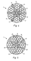
- a central core waived.
- the foot parts 8 are close to the center 12 led, but not connected to each other.
- FIG. 5 shows an embodiment of the inserts 4, at which the head part 6 'is widened to such an extent that it has a bead 10 has, which is in a room consisting of the theoretically circular circumference of the rope and the periphery two adjacent wire strands 2. This space is from the head 6 ' the insert 4 approximately filled. This results in a Roll crossing instead of a line contact - as in Fig. 1 - one Surface contact.
- Such a steel wire stranded rope is produced in the way that on a conventional wire stranding machine band-shaped profiled inserts 4 such as additional shaped wires, or wire strands handled and stranded together with the wire strands become.
Landscapes
- Ropes Or Cables (AREA)
Description
- Fig. 1
- einen Querschnitt durch eine erste Ausführungsform eines Stahldraht-Litzenseiles
- Fig.2
- eine Seitenansicht einer Einlage
- Fig.3
- eine Ansicht des Stahldraht-Litzenseiles mit schrägem Stirnanschnitt
- Fig.4
- einen Querschnitt durch eine zweite Ausführungsform ohne Kern
- Fig.5
- einen Querschnitt durch eine dritte Ausführungsform eines Stahldraht-Litzenseiles mit verbreitertem Kopfteil und ohne Kern.
Claims (2)
- Stahldraht-Litzenseil mit sechs wendelförmig verseilten Drahtlitzen wobei zwischen je zwei benachbarten Drahtlitzen (2) eine sich je über die Seillänge erstreckende bandförmige Einlage (4) vorhanden ist mit einem Kopfteil (6), einem Fussteil (8) und einem dazwischen liegenden Mittelteil (7) und wobei der Mittelteil (7) im Querschnitt zwei sich gegenüberliegende, den Querschnitt einschnürende, konkave Wölbungen (9) enthält, gegen welche die Drahtlitzen (2) anliegen, die Kopfteile (6) je am Umkreis (14) des Seiles endigen und die Fussteile (8) untereinander unverbunden sind, dadurch gekennzeichnet, dass die Fussteile (8) je eine Keilform mit einem sich je nach der Seilaussenseite öffnenden Winkel von 60° bilden, die innern Enden der Fussteile (8) gegen einen von den Drahtlitzen radial distanzierten Kern (3) anliegen oder einen zentralen Hohlraum (12) begrenzen.
- Stahldraht-Litzenseil nach Anspruch 1, dadurch gekennzeichnet, dass die Einlagen (4) aus extrudiertem oder stranggezogenem Epoxy-Vinylesterharz oder Polyäthylen bestehen.
Applications Claiming Priority (2)
| Application Number | Priority Date | Filing Date | Title |
|---|---|---|---|
| CH1741/94 | 1994-06-03 | ||
| CH01741/94A CH688915A5 (de) | 1994-06-03 | 1994-06-03 | Stahldrahtseil. |
Publications (2)
| Publication Number | Publication Date |
|---|---|
| EP0685592A1 EP0685592A1 (de) | 1995-12-06 |
| EP0685592B1 true EP0685592B1 (de) | 1999-03-17 |
Family
ID=4217500
Family Applications (1)
| Application Number | Title | Priority Date | Filing Date |
|---|---|---|---|
| EP95810339A Expired - Lifetime EP0685592B1 (de) | 1994-06-03 | 1995-05-23 | Stahldraht-Litzenseil |
Country Status (5)
| Country | Link |
|---|---|
| EP (1) | EP0685592B1 (de) |
| JP (1) | JP3493248B2 (de) |
| CN (1) | CN1121532C (de) |
| AT (1) | ATE177799T1 (de) |
| CH (1) | CH688915A5 (de) |
Cited By (1)
| Publication number | Priority date | Publication date | Assignee | Title |
|---|---|---|---|---|
| EP4424907A1 (de) * | 2023-03-01 | 2024-09-04 | Fatzer Ag | Seil, seilseele, seilinstallation und verfahren |
Families Citing this family (19)
| Publication number | Priority date | Publication date | Assignee | Title |
|---|---|---|---|---|
| CH688096A5 (de) | 1994-10-11 | 1997-05-15 | Fatzer Ag | Kunststoff-Einlage fuer ein Drahtseil. |
| NO304839B1 (no) * | 1997-03-07 | 1999-02-22 | Kv Rner Oilfield Products As | Strekklegeme og fremgangsmÕte for Õ installere strekklegeme som strekkstag pÕ oljeplattform |
| GB2332454B (en) * | 1997-12-19 | 2000-02-16 | Bridon Plc | Rope for conveying systems |
| NO321272B1 (no) | 2000-05-31 | 2006-04-10 | Aker Kvaerner Subsea As | Strekklegeme |
| EP1359248B1 (de) | 2002-05-02 | 2009-06-03 | Fatzer AG | Leuchtendes Seil |
| JP4625043B2 (ja) | 2007-03-30 | 2011-02-02 | 東京製綱株式会社 | 動索用ワイヤロープ |
| CN101793567B (zh) * | 2010-02-11 | 2011-08-31 | 中国矿业大学 | 衬垫与钢丝绳的滑动摩擦温度与应变测量方法及装置 |
| CN102345237A (zh) * | 2010-08-06 | 2012-02-08 | 贝尔卡特(青岛)钢丝产品有限公司 | 六股填充纤维芯钢丝绳及其制造工艺和专用设备 |
| EP2655234B1 (de) * | 2010-12-22 | 2023-05-17 | Otis Elevator Company | Aufzugssystem |
| EP2688827A4 (de) * | 2011-03-21 | 2014-11-19 | Otis Elevator Co | Zugglied für einen aufzug |
| AT12824U1 (de) * | 2011-04-21 | 2012-12-15 | Teufelberger Seil Ges M B H | Drahtseil mit einer langspleissverbindung |
| JP5806644B2 (ja) * | 2012-05-31 | 2015-11-10 | 東京製綱株式会社 | ハイブリッド心ロープ |
| CH707004B1 (de) | 2012-09-17 | 2016-07-29 | Fatzer Ag | Drahtseil sowie ein Zwischenstück für eine Spleissverbindung eines Drahtseils. |
| CN109295780A (zh) * | 2018-09-17 | 2019-02-01 | 江苏普乐菲塑料有限公司 | 一种高韧性的pp塑料绳 |
| CN109518501B (zh) * | 2018-12-25 | 2021-12-03 | 鞍钢钢绳有限责任公司 | 一种防腐皮带运输机钢丝绳的生产方法 |
| CN110761097B (zh) * | 2019-11-08 | 2024-04-19 | 江苏艾可森钢绳有限公司 | 一种涂塑钢丝绳 |
| CN113957734A (zh) * | 2021-10-21 | 2022-01-21 | 微山金源煤矿 | 一种钢丝绳连接套插接装置 |
| CN116200958A (zh) * | 2021-11-30 | 2023-06-02 | 扬州力达绳缆科技有限公司 | 一种船帆牵引拉拽缆绳 |
| CN117535995A (zh) * | 2023-10-24 | 2024-02-09 | 东台磊达钢帘线有限公司 | 一种避免多股钢帘线相互错位的波纹钢帘线及其制备工艺 |
Family Cites Families (4)
| Publication number | Priority date | Publication date | Assignee | Title |
|---|---|---|---|---|
| GB191027736A (en) * | 1910-08-03 | 1911-05-18 | Thomas Gore | Improvements in the Manufacture of Wire Ropes or Cables. |
| US2136865A (en) * | 1936-10-22 | 1938-11-15 | Malcolm W Reed | Wire rope |
| US2136866A (en) | 1938-06-10 | 1938-11-15 | Malcolm W Reed | Wire rope |
| JPS57121684A (en) * | 1980-12-27 | 1982-07-29 | Shinko Wire Co Ltd | Method and apparatus for producing wire rope with filler |
-
1994
- 1994-06-03 CH CH01741/94A patent/CH688915A5/de not_active IP Right Cessation
-
1995
- 1995-05-23 AT AT95810339T patent/ATE177799T1/de not_active IP Right Cessation
- 1995-05-23 EP EP95810339A patent/EP0685592B1/de not_active Expired - Lifetime
- 1995-06-03 CN CN95108574A patent/CN1121532C/zh not_active Expired - Fee Related
- 1995-06-05 JP JP16015995A patent/JP3493248B2/ja not_active Expired - Fee Related
Cited By (1)
| Publication number | Priority date | Publication date | Assignee | Title |
|---|---|---|---|---|
| EP4424907A1 (de) * | 2023-03-01 | 2024-09-04 | Fatzer Ag | Seil, seilseele, seilinstallation und verfahren |
Also Published As
| Publication number | Publication date |
|---|---|
| ATE177799T1 (de) | 1999-04-15 |
| CN1119230A (zh) | 1996-03-27 |
| EP0685592A1 (de) | 1995-12-06 |
| CN1121532C (zh) | 2003-09-17 |
| CH688915A5 (de) | 1998-05-29 |
| JPH08170287A (ja) | 1996-07-02 |
| JP3493248B2 (ja) | 2004-02-03 |
Similar Documents
| Publication | Publication Date | Title |
|---|---|---|
| EP0685592A1 (de) | Stahldraht-Litzenseil | |
| DE69811271T2 (de) | Stahlseil mit gewellten elementen | |
| DE2619086C2 (de) | Verstärkungsseil für Elastomererzeugnisse, Verfahren und Vorrichtung zur Herstellung | |
| DE10124362B4 (de) | Zugelement für Aufzüge | |
| DE3317744C2 (de) | Verstärkungscord mit Umschlingungsdraht | |
| DE69315181T2 (de) | Stahlseil mit mehreren Litzen | |
| DE69110771T2 (de) | Stahlkabel zur Verstärkung von elastomeren Erzeugnissen. | |
| EP1550629B1 (de) | Aufzugssystem | |
| DE69516259T2 (de) | Stahlseile zur Verstärkung elastomerer Erzeugnisse | |
| DE3149783C2 (de) | Drahtseil | |
| DE69002107T2 (de) | Metalldrahtkabel zur Verstärkung von Elastomeren. | |
| DE60121671T2 (de) | Drahtseil für Kraftwagenfensterheber | |
| DE2943830A1 (de) | Metallschnur | |
| DE68910294T2 (de) | Verbundstahlkord. | |
| DE112016006384B4 (de) | Fahrstuhl-Seil und zugehöriges Herstellungsverfahren | |
| CH674226A5 (de) | ||
| DE19526721B4 (de) | Reifencord | |
| DE69806809T2 (de) | Seil für förderanlagen | |
| DE3510384C2 (de) | ||
| DE69503676T2 (de) | Verstärkung für Fahrzeugreifen | |
| AT395731B (de) | Metallkord zur verstaerkung von elastomerkoerpern | |
| DE4212846C2 (de) | Verstärkungscord für elastomere Erzeugnisse | |
| DE2903854A1 (de) | Dreikantlitzenseil | |
| EP2708642A2 (de) | Drahtseil sowie ein Zwischenstück für dessem verspleissten Bereich | |
| EP1001831A1 (de) | Rohr sowie golfschläger mit schaft aus diesem rohr |
Legal Events
| Date | Code | Title | Description |
|---|---|---|---|
| PUAI | Public reference made under article 153(3) epc to a published international application that has entered the european phase |
Free format text: ORIGINAL CODE: 0009012 |
|
| AK | Designated contracting states |
Kind code of ref document: A1 Designated state(s): AT CH FR GB IT LI |
|
| 17P | Request for examination filed |
Effective date: 19960202 |
|
| 17Q | First examination report despatched |
Effective date: 19970320 |
|
| GRAG | Despatch of communication of intention to grant |
Free format text: ORIGINAL CODE: EPIDOS AGRA |
|
| GRAG | Despatch of communication of intention to grant |
Free format text: ORIGINAL CODE: EPIDOS AGRA |
|
| GRAG | Despatch of communication of intention to grant |
Free format text: ORIGINAL CODE: EPIDOS AGRA |
|
| GRAH | Despatch of communication of intention to grant a patent |
Free format text: ORIGINAL CODE: EPIDOS IGRA |
|
| GRAH | Despatch of communication of intention to grant a patent |
Free format text: ORIGINAL CODE: EPIDOS IGRA |
|
| GRAA | (expected) grant |
Free format text: ORIGINAL CODE: 0009210 |
|
| AK | Designated contracting states |
Kind code of ref document: B1 Designated state(s): AT CH FR GB IT LI |
|
| REF | Corresponds to: |
Ref document number: 177799 Country of ref document: AT Date of ref document: 19990415 Kind code of ref document: T |
|
| REG | Reference to a national code |
Ref country code: CH Ref legal event code: EP |
|
| ITF | It: translation for a ep patent filed | ||
| REG | Reference to a national code |
Ref country code: CH Ref legal event code: NV Representative=s name: LUCHS & PARTNER PATENTANWAELTE |
|
| GBT | Gb: translation of ep patent filed (gb section 77(6)(a)/1977) |
Effective date: 19990601 |
|
| ET | Fr: translation filed | ||
| PLBE | No opposition filed within time limit |
Free format text: ORIGINAL CODE: 0009261 |
|
| STAA | Information on the status of an ep patent application or granted ep patent |
Free format text: STATUS: NO OPPOSITION FILED WITHIN TIME LIMIT |
|
| 26N | No opposition filed | ||
| REG | Reference to a national code |
Ref country code: GB Ref legal event code: IF02 |
|
| PGFP | Annual fee paid to national office [announced via postgrant information from national office to epo] |
Ref country code: FR Payment date: 20100608 Year of fee payment: 16 |
|
| PGFP | Annual fee paid to national office [announced via postgrant information from national office to epo] |
Ref country code: IT Payment date: 20100527 Year of fee payment: 16 Ref country code: AT Payment date: 20100520 Year of fee payment: 16 |
|
| PGFP | Annual fee paid to national office [announced via postgrant information from national office to epo] |
Ref country code: CH Payment date: 20100527 Year of fee payment: 16 |
|
| PGFP | Annual fee paid to national office [announced via postgrant information from national office to epo] |
Ref country code: GB Payment date: 20100521 Year of fee payment: 16 |
|
| REG | Reference to a national code |
Ref country code: CH Ref legal event code: PL |
|
| GBPC | Gb: european patent ceased through non-payment of renewal fee |
Effective date: 20110523 |
|
| PG25 | Lapsed in a contracting state [announced via postgrant information from national office to epo] |
Ref country code: LI Free format text: LAPSE BECAUSE OF NON-PAYMENT OF DUE FEES Effective date: 20110531 Ref country code: CH Free format text: LAPSE BECAUSE OF NON-PAYMENT OF DUE FEES Effective date: 20110531 |
|
| REG | Reference to a national code |
Ref country code: AT Ref legal event code: MM01 Ref document number: 177799 Country of ref document: AT Kind code of ref document: T Effective date: 20110523 |
|
| REG | Reference to a national code |
Ref country code: FR Ref legal event code: ST Effective date: 20120131 |
|
| PG25 | Lapsed in a contracting state [announced via postgrant information from national office to epo] |
Ref country code: IT Free format text: LAPSE BECAUSE OF NON-PAYMENT OF DUE FEES Effective date: 20110523 Ref country code: AT Free format text: LAPSE BECAUSE OF NON-PAYMENT OF DUE FEES Effective date: 20110523 |
|
| PG25 | Lapsed in a contracting state [announced via postgrant information from national office to epo] |
Ref country code: FR Free format text: LAPSE BECAUSE OF NON-PAYMENT OF DUE FEES Effective date: 20110531 |
|
| PG25 | Lapsed in a contracting state [announced via postgrant information from national office to epo] |
Ref country code: GB Free format text: LAPSE BECAUSE OF NON-PAYMENT OF DUE FEES Effective date: 20110523 |