EP0686834B1 - Dispositif pour la détermination et/ou la surveillance d'un niveau prédéterminé dans un réservoir - Google Patents
Dispositif pour la détermination et/ou la surveillance d'un niveau prédéterminé dans un réservoir Download PDFInfo
- Publication number
- EP0686834B1 EP0686834B1 EP95108009A EP95108009A EP0686834B1 EP 0686834 B1 EP0686834 B1 EP 0686834B1 EP 95108009 A EP95108009 A EP 95108009A EP 95108009 A EP95108009 A EP 95108009A EP 0686834 B1 EP0686834 B1 EP 0686834B1
- Authority
- EP
- European Patent Office
- Prior art keywords
- circuit
- channel
- transducer
- frequency
- measuring signal
- Prior art date
- Legal status (The legal status is an assumption and is not a legal conclusion. Google has not performed a legal analysis and makes no representation as to the accuracy of the status listed.)
- Expired - Lifetime
Links
- 238000012544 monitoring process Methods 0.000 title claims description 11
- 238000011156 evaluation Methods 0.000 claims description 26
- 230000005284 excitation Effects 0.000 claims description 11
- 239000000463 material Substances 0.000 claims description 9
- 230000010355 oscillation Effects 0.000 claims description 6
- 230000005540 biological transmission Effects 0.000 claims description 5
- 230000000737 periodic effect Effects 0.000 claims description 2
- 230000003534 oscillatory effect Effects 0.000 claims 5
- 230000000977 initiatory effect Effects 0.000 claims 1
- 238000005259 measurement Methods 0.000 description 46
- 238000010586 diagram Methods 0.000 description 9
- 239000012528 membrane Substances 0.000 description 7
- 238000000034 method Methods 0.000 description 3
- 230000000295 complement effect Effects 0.000 description 2
- 239000013078 crystal Substances 0.000 description 2
- 239000007788 liquid Substances 0.000 description 2
- 230000007257 malfunction Effects 0.000 description 2
- 230000010358 mechanical oscillation Effects 0.000 description 2
- 230000000630 rising effect Effects 0.000 description 2
- 230000001960 triggered effect Effects 0.000 description 2
- 230000037007 arousal Effects 0.000 description 1
- 230000007797 corrosion Effects 0.000 description 1
- 238000005260 corrosion Methods 0.000 description 1
- 238000001514 detection method Methods 0.000 description 1
- 238000011161 development Methods 0.000 description 1
- 230000018109 developmental process Effects 0.000 description 1
- 230000001771 impaired effect Effects 0.000 description 1
- 238000003780 insertion Methods 0.000 description 1
- 230000037431 insertion Effects 0.000 description 1
- 238000009434 installation Methods 0.000 description 1
- 238000004519 manufacturing process Methods 0.000 description 1
Images

Classifications
-
- G—PHYSICS
- G01—MEASURING; TESTING
- G01F—MEASURING VOLUME, VOLUME FLOW, MASS FLOW OR LIQUID LEVEL; METERING BY VOLUME
- G01F23/00—Indicating or measuring liquid level or level of fluent solid material, e.g. indicating in terms of volume or indicating by means of an alarm
- G01F23/22—Indicating or measuring liquid level or level of fluent solid material, e.g. indicating in terms of volume or indicating by means of an alarm by measuring physical variables, other than linear dimensions, pressure or weight, dependent on the level to be measured, e.g. by difference of heat transfer of steam or water
- G01F23/28—Indicating or measuring liquid level or level of fluent solid material, e.g. indicating in terms of volume or indicating by means of an alarm by measuring physical variables, other than linear dimensions, pressure or weight, dependent on the level to be measured, e.g. by difference of heat transfer of steam or water by measuring the variations of parameters of electromagnetic or acoustic waves applied directly to the liquid or fluent solid material
- G01F23/296—Acoustic waves
- G01F23/2966—Acoustic waves making use of acoustical resonance or standing waves
- G01F23/2967—Acoustic waves making use of acoustical resonance or standing waves for discrete levels
Definitions
- the invention relates to an arrangement for detection and / or monitoring a predetermined fill level in one Container using a level sensor, which is a mechanical Vibration system, an electromechanical excitation converter and at least one electromechanical receive converter contains, with the mechanical vibration system on the Height of the predetermined level is attached so that it comes into contact with the filling material if it has the predetermined Level reached, and the receiving transducer is connected to the input of a first circuit channel, which contains an amplifier circuit, the output of which with the Excitation converter is connected and which is designed that the mechanical vibration system to vibrate with its Natural resonance frequency is excited, and with an evaluation device for triggering display and / or switching processes depending on the frequency of the output signal the amplifier circuit, the circuit channel further contains a measuring signal converter, one for transmission the evaluation device generates a suitable measurement signal that Information about the frequency of the output signal of the Includes amplifier circuit.
- a level sensor which is a mechanical Vibration system
- an electromechanical excitation converter and at least one electromechanical receive converter contains, with the mechanical vibration system on the Height of
- this instantaneous frequency by more than a predetermined difference is lower than the nominal frequency, it is assumed that the mechanical vibrating system in contact with the product stands, while in the other case it is assumed that mechanical vibration system vibrates in air.
- a maximum fill level overfill protection
- monitoring a minimal Level means the first case that the one to be monitored Level in the container has not yet been reached, and the second case that the level to be monitored in the container reached or fallen short of.
- the evaluation device can use the frequency determined by it also certain errors in the level monitoring arrangement detect. If the measured frequency is zero, there is a Total failure of the device. If the measured frequency is significantly higher than the nominal frequency, it is suspected that the vibrating rods are shortened by corrosion or demolition are. In such cases, the evaluation device can Issue alarm signal; is monitoring the level but then no longer possible until the error has been rectified.
- a second circuit channel is provided, which is constructed in the same way as the first circuit channel and with the excitation and reception transducers of the mechanical Vibration system is connected to a control circuit is provided, the two circuit channels alternately activated, and that the transducer each Circuit channel is designed so that it to the measurement signal adds an identifier associated with the circuit channel that from the identifier assigned to the other circuit channel is different.
- the evaluation device receives in regular operation, the measurement signals of the one and the other circuit channel; these measurement signals contain the same information about the one to be monitored Frequency and differ only in the identifier the circuit channel from which the measurement signal just received comes from.
- the evaluation device can be identified using the identifiers the perfect functioning of the electronic at all times Check the circuits of the level sensor and additional information when errors occur win. For example, if one of the two circuit channels fails, there are pauses in the transmitted measurement signals, and from the measurement signals still transmitted that can Identify the evaluation device based on the identifier which of the both circuit channels has failed.
- the evaluation device recognizes that the regular changes between the switching channels are not more takes place. In every such malfunction, that solves Evaluation device an alarm so that the fault is remedied is, however, it can monitor the level now continue as long as there are still measurement signals from one of the receives two circuit channels.
- Fig. 1 of the drawing shows a level sensor 10 with a mechanical vibration system 11, an electromechanical Excitation converter 12 and two electromechanical receive converters 13 and 14.
- the mechanical vibration system 11 consists of two vibrating bars in the example shown 15 and 16, each with one end at one common membrane 17 are attached all around their Circumferential edge with an annular screw-in piece 18 connected is.
- the electromechanical excitation converter 12 is designed so that it is a supplied electrical AC signal (AC voltage or AC) into one can convert mechanical vibration, and either of the two electromechanical receiving transducer 13, 14 is designed that he has a mechanical vibration acting on him can convert into an alternating electrical signal.
- each converter 12, 13, 14 a piezoelectric transducer, which is at least one piezoelectric Contains item.
- Such a piezoelectric Element is known to consist of a disc-shaped Piezo crystal, which is arranged between two electrodes.
- the thickness of the piezo crystal changes depending on the voltage applied to the electrodes, and vice versa mechanically forced changes in thickness produce an electrical Voltage on the electrodes.
- the arousal converter 12 is connected to the membrane 17 that it due to the Thickness vibrations of his piezocrystal when applied an electrical alternating voltage are generated, the Diaphragm vibrated on the two Vibrating rods are transmitted so that these vibrating rods opposite mechanical vibrations transverse to their longitudinal direction To run.
- Each receive converter 13, 14 is so with the membrane 17 connected that due to the mechanical Vibrations of the membrane and the vibrating rods are electrical AC voltage between its two electrodes is produced.
- connection 22 for the excitation converter 12 is connected to a ground connection, for example formed by the membrane 17 and the screw 18 can be.
- the other electrodes form a connection 22 for the excitation converter 12, a connection 23 for the Receive converter 13 or a connection 24 for the receive converter 14.
- the connection 23 of the receiving transducer 13 is with the input of a circuit channel 30 connected in series an input amplifier 31, a phase shifter 32, a power amplifier 33, a channel switch 34 and one Measuring signal converter 35 contains.
- the connection 22 of the excitation converter 12 is via a diode 36 to the output of the channel switch 34 connected.
- connection is 24 of the receive converter 14 with the input of a circuit channel 40 connected, in completely the same way as that Circuit channel 30 is formed and thus one behind the other an input amplifier 41, a phase shifter 42, one Power amplifier 43, a channel switch 44 and a measurement signal converter 45 contains, the terminal 22 of the excitation transducer 12 via a diode 46 to the output of the Channel switch 44 is connected.
- a control circuit 50 puts on the two channel switches 34 and 44 to each other complementary control signals, so that the channel switch 44th is open when the channel switch 34 is closed, and vice versa. These control signals are preferably periodic and symmetrical, so that each channel switch alternately for same times open and closed.
- the period of Control signals can be 1 Hz, for example, so that each channel switch alternately open for 0.5 s and for 0.5 s is closed.
- the channel switches 34 and 44 that represented symbolically by mechanical switch contacts are, of course, really fast electronic ones Switches designed for example in CMOS technology are.
- the level sensor lies 10 with the two transducers 12 and 13 that over the mechanical vibration system 11 are coupled to one another, in the feedback circuit of the amplifier circuit of the circuit channel 30 by circuits 31, 32 and 33 is formed.
- This amplifier circuit is designed that the self-excitation condition is fulfilled, so that the mechanical vibration system 11 via the two transducers 12 and 13 excited to vibrate at its natural resonance frequency becomes.
- the channel switch 44 is closed, is the level sensor 10 with the two transducers 12 and 14, which are connected to one another via the mechanical vibration system 11 are coupled, in the feedback circuit of the amplifier circuit of the circuit channel 40 through the circuits 41, 42 and 43 is formed.
- This amplifier circuit too is designed so that the self-excitation condition is met is so that the mechanical vibration system 11 over the two Transducers 12 and 14 vibrate at its natural resonance frequency is excited.
- the level sensor 10 attached to the container in a known manner that the two vibrating rods 15 and 16 with the contents in Come into contact when this reaches the predetermined level reached. If the predetermined level in the container is not is reached, the two vibrating rods 15 and 16 swing in Air.
- the natural resonance frequency of the mechanical vibration system 11 a known value, the for example, 450 Hz.
- the two Vibrating rods 15 and 16 come into contact with the filling material, takes the natural resonance frequency of the mechanical vibration system from; it is, for example, for a filling product high density or high viscosity about 100 Hz if the two vibrating rods completely covered by the filling material are. Based on the frequency of the output signal of the power amplifier 33 or 43, which always with the vibration frequency of the mechanical vibration system 11 matches, can then be determined whether the contents in the container has reached the predetermined level or not.
- the measuring signal converter 35 the output signal of the power amplifier 33 receives when the channel switch 34 is closed is at the output provides a measurement signal that contains the information about the vibration frequency of the mechanical vibration system 11 contains.
- a measurement signal that contains the same information is supplied by the output of the measuring signal converter 45, when the channel switch 44 is closed.
- the outputs of the two transducers 35 and 45 are connected to the inputs a transmission circuit 51 connected, the output of a line 52 is connected to an evaluation device 53, which can be located remotely while the remaining circuits shown in Fig. 1, the on-site electronics form which is located at the location of the container whose fill level is monitored with the aid of the fill level sensor 10 becomes.
- the evaluation device 53 thus receives that from the Measurement signal converter 35 generated measurement signal when the channel switch 34 is closed, while the transducer 45 then no measurement signal generated since the channel switch 44 is open and diode 46 prevents the output signal of the power amplifier 33 arrives at the measuring signal converter 45; against it receives the evaluation device 53 that of the measurement signal converter 45 generated measurement signal when the channel switch 44 is closed is, while the measurement signal converter 35 then does not generate a measurement signal, because the channel switch 34 is open and the diode 36 prevents the output signal of the power amplifier 43 from Measuring signal converter 35 arrives. From every received measurement signal can the evaluation device 53 the oscillation frequency of the determine mechanical vibration system 11 and determine from it, whether the level to be monitored in the container is reached or not.
- Line 52 is a common practice Two-wire line, on the one hand, the supply current from the evaluation device 53 to the one at the level of the level sensor 10 on-site electronics is supplied, and via the on the other hand, the measurement signals from the on-site electronics to Evaluation device 53 are transmitted.
- the measurement signal converter 35 and 45 are therefore designed so that they generate measurement signals, the supply current transmitted via line 52 can be overlaid. This can be due to a known way that the measurement signals pulses are with the information about the vibration frequency of the mechanical vibration system 11 are modulated.
- the modulation given to the pulses is pulse frequency modulation (PFM), so that the line 52 to Evaluation device 53 transmitted pulses a repetition frequency have the same as the vibration frequency of the mechanical Vibration system 11 is or in a known ratio to this vibration frequency.
- the transmission circuit 51 is designed in a manner known per se so that it the PFM pulses the supply current on line 52 superimposed, and the evaluation device 53 is designed such that the superimposed PFM pulses from the supply current separates.
- a special feature of the arrangement described here is not only in that two identical circuit channels 30 and 40 are provided, alternately by closing the associated Channel switch 34 or 44 are activated, but also in that each measuring signal converter 35 or 45 that of it generates a measurement signal adds an identifier that the Circuit channel identifies and from the identifier of the other Circuit channel is different, so that the evaluation device 53 can recognize from which circuit channel the measurement signal that it is currently receiving.
- the identifiers are formed in the case can that the measurement signals are PFM pulses.
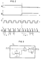
- Diagram A of Fig. 2 shows the control signal that of the control circuit 50 is applied to the channel switch 34 and diagram B shows the complementary one Control signal applied to the channel switch 44.
- Each channel switch is closed when the applied Control signal has the high signal value and it is open when the applied control signal has the low signal value
- Has. 2 correspond to those on the left of the dash-dotted line Diagrams depicting the state in the line the circuit channel 30 is activated, and that in the right Diagrams shown in part correspond to the state in which the circuit channel 40 is activated.
- Diagram C of FIG. 2 shows the output signals of the power amplifiers 33 and 43 in the respectively activated circuit channel; these output signals are identical.
- the output amplifiers 33 and 43 are limiter amplifiers which emit square-wave voltages at the output, the frequency of which is equal to the oscillation frequency of the mechanical oscillation system 11.
- Each measuring signal converter 35 and 45 generates a short measuring pulse M of duration T I for each rising edge of the square wave voltage; the repetition frequency of these measurement pulses M is thus equal to the oscillation frequency of the mechanical vibration system 11.
- the measurement signal converter 35 generates a short identification pulse K in each period T M of the measurement pulses M, which follows the measurement pulse M at a fixed time interval T 1 and preferably has the same duration T has I ; in the same way, the measurement signal converter 45 generates in each period of the measurement pulses M a short identification pulse K of the duration T I , which follows the measurement pulse M at a fixed time interval T 2 , the time interval T 2 being different from the time interval T 1 . It can thus be seen from the time intervals T 1 and T 2 from which circuit channel the measurement signals originate.
- the time interval T 1 forms the identifier for the circuit channel 30, and the time interval T 2 forms the identifier for the circuit channel 40.
- Fig. 3 shows an embodiment of the measurement signal converter 35, with which the previously described measurement and identification pulses can be generated.
- the square-wave signal supplied by the power amplifier 33 and transmitted via the closed channel switch 34 is applied via an EXCLUSIVE-OR circuit 55 to a monoflop 56, which is triggered by each rising edge of the square-wave signal and generates a measuring pulse M of duration T I.
- the same square-wave signal is also applied to a second monoflop 57, the hold time of which is equal to the time interval T 1 for the identification of the circuit channel 30.
- the monoflop 57 After each triggering, the monoflop 57 thus generates a rectangular pulse of the duration T 1 , which is fed to the monoflop 56 via the second input of the EXCLUSIVE-OR circuit 55, which is triggered again by the trailing edge of this rectangular pulse and an identification pulse K of the duration T I generated, which follows the previously generated measuring pulse M at time interval T 1 .
- the measurement signal converter 45 of the second circuit channel 40 is constructed in the same way, but with the difference that the hold time of the second monoflop is set to the time interval T 2 .
- the determination of the oscillation frequency of the mechanical oscillation system 11 in the evaluation device 53 is in no way impaired by the additional identification pulses. If the vibration frequency is determined by counting the pulses of the measurement signal at predetermined time intervals, the identification pulses result in only twice the number of pulses per time interval, which can easily be taken into account when calculating the vibration frequency. If, on the other hand, the oscillation frequency is determined by measuring the subsequent period T M of the measuring pulses, this subsequent period can easily be obtained by measuring two successive time intervals between pulses and adding these time intervals, since one of these time intervals is the time interval T 1 or T 2 between a measuring pulse M and the following identification pulse K and the other time interval is that between an identification pulse K and the following measuring pulse M.
- the evaluation device 53 can be operated at any time check the proper functioning of the on-site electronics and additional information when errors occur win. For example, if one of the two circuit channels 30, 40 fails, there are breaks of each 0.5 s in the transmitted measurement signals, and from the still The evaluation device 53 can transmit the measurement signals on hand identify which of the two circuit channels has failed. If, on the other hand, measurement signals are transmitted without gaps are recognized, but the identifier remains unchanged the evaluation device 53 that the regular change between the circuit channels no longer takes place, which in particular conclude that the control circuit 50 has failed leaves. The evaluation unit triggers in such a malfunction an alarm so that the fault can be rectified, it can however, continue to monitor the level, as long as they still have measurement signals from one of the two circuit channels receives.
- the mechanical Vibration system 11 contains two receiving transducers 13, 14 from which the one receive converter 13 with the one circuit channel 30 and the other receive converter with the other Circuit channel 40 is connected. Basically, that would Arrangement also work with a single receive transducer, to which both circuit channels would be connected; however, the use of two receive converters enables a better mutual decoupling of the circuit channels.
- the arrangement described is not on the Use of mechanical vibration systems with two Vibrating bars limited; it can also be used with level sensors be equipped with only one vibrating rod, or with level sensors without vibrating rods, where only the vibrating membrane with the product in Contact comes.
- the previously described transmission of PFM measurement signals corresponds a preferred technique because the frequency to be measured directly through the repetition frequency of the PFM pulses can be expressed and because the PFM impulses on particular simple way the supply direct current on the two-wire line can be overlaid.
- this technique proves to be particularly inexpensive because it the insertion of the identifier into the measurement signal in a simple manner in the form of the time interval of identification pulses.
- the principle described can also applied to other types of measurement signals, provided that this one identifies the circuit channel ID can be added.
Landscapes
- Physics & Mathematics (AREA)
- Acoustics & Sound (AREA)
- Electromagnetism (AREA)
- Thermal Sciences (AREA)
- Fluid Mechanics (AREA)
- General Physics & Mathematics (AREA)
- Measurement Of Levels Of Liquids Or Fluent Solid Materials (AREA)
- Arrangements For Transmission Of Measured Signals (AREA)
- Burglar Alarm Systems (AREA)
Claims (4)
- Dispositif pour la détermination et/ou la surveillance d'un niveau de remplissage prédéterminé dans un récipient à l'aide d'une sonde de niveau de remplissage qui comprend un système à vibration mécanique, un convertisseur d'excitation électromécanique et au moins un convertisseur de réception électromécanique, le système oscillant mécanique étant placé à la hauteur du niveau de remplissage prédéterminé de manière à venir en contact avec la charge quand celle-ci atteint le niveau de remplissage prédéterminé et le convertisseur de réception étant relié à l'entrée d'un premier canal de circuit qui contient un montage amplificateur dont la sortie est reliée au convertisseur d'excitation et qui est conçu de manière à exciter le système mécanique oscillant pour qu'il effectue des oscillations avec une fréquence de résonance propre, et est reliée à un appareil d'évaluation pour le déclenchement d'opérations d'affichage et/ou de commande en fonction de la fréquence du signal de sortie du montage amplificateur, le premier canal de circuit comprenant en outre un convertisseur de signal de mesure qui génère son propre signal de mesure pour la transmission à l'appareil d'évaluation, signal qui contient l'information sur la fréquence du signal de sortie du montage amplificateur, caractérisé en ce qu'il est prévu un second canal de circuit qui est réalisé de la même manière que le premier canal de circuit et qui est relié aux convertisseurs de réception et d'excitation du système mécanique oscillant, en ce qu'il est prévu un circuit de commande qui active en alternance les deux canaux de circuit et en ce que le convertisseur de signal de mesure de chaque canal de circuit est conçu pour ajouter au signal de mesure une indication caractéristique associée au canal de circuit qui est différente de l'indication caractéristique associée à l'autre canal de circuit.
- Dispositif selon la revendication 1, caractérisé en ce que chaque canal de circuit comprend un interrupteur de canal et en ce que le circuit de commande ouvre et ferme en alternance les interrupteurs des deux canaux de circuit.
- Dispositif selon la revendication 1 ou 2, caractérisé en ce que le système mécanique oscillant présente deux convertisseurs de réception dont l'un est relié à l'entrée de l'un des canaux de circuit et l'autre à l'entrée de l'autre canal de circuit.
- Dispositif selon l'une des revendications précédentes, caractérisé en ce que chaque convertisseur de signal de mesure génère un signal de mesure à modulation d'impulsions en fréquence qui se compose d'une suite périodique de courtes impulsions de mesure dont la fréquence en série se trouve dans un rapport connu vis-à-vis de la fréquence du signal de sortie du montage amplificateur et en ce que chaque convertisseur de signaux de mesure génère dans chaque période du signal de mesure une impulsion courte d'indication caractéristique qui suit l'impulsion de mesure précédente à un intervalle de temps prédéterminé, les intervalles de temps étant différents les uns des autres dans les deux canaux de circuit et représentant les indications caractéristiques des canaux de circuit.
Applications Claiming Priority (2)
| Application Number | Priority Date | Filing Date | Title |
|---|---|---|---|
| DE4419617A DE4419617C2 (de) | 1994-06-03 | 1994-06-03 | Anordnung zur Feststellung und/oder Überwachung eines vorbestimmten Füllstands in einem Behälter |
| DE4419617 | 1994-06-03 |
Publications (2)
| Publication Number | Publication Date |
|---|---|
| EP0686834A1 EP0686834A1 (fr) | 1995-12-13 |
| EP0686834B1 true EP0686834B1 (fr) | 1999-03-17 |
Family
ID=6519831
Family Applications (1)
| Application Number | Title | Priority Date | Filing Date |
|---|---|---|---|
| EP95108009A Expired - Lifetime EP0686834B1 (fr) | 1994-06-03 | 1995-05-24 | Dispositif pour la détermination et/ou la surveillance d'un niveau prédéterminé dans un réservoir |
Country Status (6)
| Country | Link |
|---|---|
| US (1) | US5631633A (fr) |
| EP (1) | EP0686834B1 (fr) |
| JP (1) | JP2716678B2 (fr) |
| CA (1) | CA2150855C (fr) |
| DE (2) | DE4419617C2 (fr) |
| ES (1) | ES2128609T3 (fr) |
Families Citing this family (25)
| Publication number | Priority date | Publication date | Assignee | Title |
|---|---|---|---|---|
| EP0762088A3 (fr) * | 1995-09-11 | 1997-11-05 | Georg Fischer Rohrleitungssysteme AG | Procédé et dispositif pour la détection d'un niveau critique pour fluides et matière en vrac |
| US5969621A (en) * | 1997-04-30 | 1999-10-19 | Endress + Hauser Gmbh + Co. | Apparatus for establishing and/or monitoring a predetermined filling level in a container |
| DE59712748D1 (de) * | 1997-04-30 | 2006-11-23 | Endress & Hauser Gmbh & Co Kg | Vorrichtung zur Feststellung und/oder Überwachung eines vorbestimmten Füllstands in einem Behälter |
| EP0875741B1 (fr) * | 1997-04-30 | 2008-08-20 | Endress + Hauser GmbH + Co. KG | Dispositif pour la détermination et/ou la surveillance d'un niveau prédéterminé dans un réservoir |
| US6138507A (en) * | 1997-04-30 | 2000-10-31 | Endress + Hauser Gmbh + Co. | Apparatus for establishing and/or monitoring a predetermined filling level in a container through controlled transducer phase and impedance |
| DE59712903D1 (de) * | 1997-04-30 | 2008-01-31 | Endress & Hauser Gmbh & Co Kg | Vorrichtung zur Feststellung und/oder Überwachung eines vorbestimmten Füllstands in einem Behälter |
| US5844491A (en) * | 1997-04-30 | 1998-12-01 | Endress + Hauser Gmbh + Co. | Apparatus for establishing and/or monitoring a predetermined filling level in a container |
| EP0875739B1 (fr) * | 1997-04-30 | 2006-10-18 | Endress + Hauser GmbH + Co. KG | Dispositif pour la détermination et/ou la surveillance d'un niveau prédéterminé dans un réservoir |
| DE19840796C1 (de) * | 1998-09-08 | 2000-03-09 | Grieshaber Vega Kg | Verfahren zum Betreiben und Funktionstesten eines Vibrationsgrenzstandsensors und hierfür geeigneter Vibrationsgrenzstandsensor |
| US6236322B1 (en) | 1998-09-09 | 2001-05-22 | Endress + Hauser Gmbh + Co. | Apparatus for establishing and/or monitoring a predetermined filling level in a container |
| EP0985916B1 (fr) * | 1998-09-09 | 2007-07-18 | Endress + Hauser GmbH + Co. KG | Dispositif de détection et/ou de surveillance d'un niveau prédéterminé dans un résevoir |
| JP2000283825A (ja) * | 1999-03-31 | 2000-10-13 | Fuji Photo Film Co Ltd | 液面検出装置 |
| DE50106202D1 (de) * | 2000-03-08 | 2005-06-16 | Endress & Hauser Gmbh & Co Kg | Vorrichtung zur feststellung und/oder überwachung eines vorbestimmten füllstandes in einem behälter |
| CN1214237C (zh) * | 2001-03-28 | 2005-08-10 | 恩德莱斯和豪瑟尔两合公司 | 用于确定和/或监控容器内预定填充液面的装置 |
| JP2004526251A (ja) * | 2001-03-28 | 2004-08-26 | エンドレス ウント ハウザー ゲーエムベーハー ウント コンパニー コマンディートゲゼルシャフト | 容器内の所定の充填レベルを決定及び/又は監視する装置 |
| DE10129556A1 (de) * | 2001-06-19 | 2003-01-09 | Endress & Hauser Gmbh & Co Kg | Vorrichtung zur Bestimmung und/oder Überwachung des Füllstandes eines Mediums in einem Behälter |
| DE10234303A1 (de) * | 2002-07-26 | 2004-02-19 | Endress + Hauser Gmbh + Co. Kg | Vorrichtung zur Bestimmung und/oder Überwachung einer physikalischen oder chemischen Prozeßgröße |
| BRPI0418141A2 (pt) | 2003-12-23 | 2017-03-01 | Inesa East Ltd | um método para a avaliação não evasiva do nível do material de enchimento de um recipiente |
| US7819144B2 (en) * | 2005-09-01 | 2010-10-26 | Wotring Blake R | Method and apparatus for loading and conditioning materials |
| DE102010039585A1 (de) | 2010-08-20 | 2012-02-23 | Endress + Hauser Gmbh + Co. Kg | Vorrichtung zur Bestimmung und/oder Überwachung zumindest eines vorbestimmten Füllstands |
| DE102011088304B4 (de) * | 2011-12-12 | 2023-09-21 | Endress+Hauser SE+Co. KG | Vorrichtung zur Bestimmung und/oder Überwachung mindestens einer Prozessgröße |
| CN105209901B (zh) | 2013-02-06 | 2018-08-24 | 乌尔蒂莫测量有限责任公司 | 用于测量容器中自由流动物质的物理性质的非侵入性方法 |
| US9816848B2 (en) | 2014-01-23 | 2017-11-14 | Ultimo Measurement Llc | Method and apparatus for non-invasively measuring physical properties of materials in a conduit |
| DE102014115693A1 (de) * | 2014-10-29 | 2016-05-04 | Endress + Hauser Gmbh + Co. Kg | Vibronischer Sensor |
| CN112146718B (zh) * | 2020-08-19 | 2022-06-17 | 天津大学 | 一种基于涡街传感器的质量流量测量方法 |
Family Cites Families (15)
| Publication number | Priority date | Publication date | Assignee | Title |
|---|---|---|---|---|
| US4400976A (en) * | 1980-07-02 | 1983-08-30 | Purecycle Corporation | Ultrasonic transceiver circuit for level sensing |
| GB2090415A (en) * | 1980-12-30 | 1982-07-07 | Haynes Joel Erwin | Liquid level meter |
| US4540981A (en) * | 1981-10-29 | 1985-09-10 | Edo Western Corporation | Method and apparatus for detecting the presence of liquid |
| DE3336991A1 (de) * | 1983-10-11 | 1985-05-02 | Endress U. Hauser Gmbh U. Co, 7867 Maulburg | Vorrichtung zur feststellung und/oder ueberwachung eines vorbestimmten fuellstands in einem behaelter |
| DE3516200A1 (de) * | 1985-05-06 | 1986-11-06 | Schittek, Margarete, 2805 Stuhr | Verfahren zur fuellstandskontrolle und einrichtung zur durchfuehrung des verfahrens |
| US4785664A (en) * | 1986-04-28 | 1988-11-22 | Kay-Ray, Inc. | Ultrasonic sensor |
| JPS62178329U (fr) * | 1986-05-01 | 1987-11-12 | ||
| US4742244A (en) * | 1986-10-15 | 1988-05-03 | Itt Avionics | Electronic float switch apparatus |
| DD260325A1 (de) * | 1987-04-29 | 1988-09-21 | Greiz Plasttechnik | Vorrichtung zur fuellstandsgrenzmessung und fuellstandsregelung von vorwiegend sehr leichten, rieselfaehigen schuettguetern, insbesondere von vorgeschaeumtem expandierbaren polystyrol (eps) |
| JPS6410236A (en) * | 1987-07-02 | 1989-01-13 | Matsushita Electric Industrial Co Ltd | Pattern forming material |
| DE3931453C1 (fr) * | 1989-09-21 | 1991-02-28 | Endress U. Hauser Gmbh U. Co, 7864 Maulburg, De | |
| US5062295A (en) * | 1990-12-24 | 1991-11-05 | Sparktech | Dual tube sonic level gage |
| GB2254429A (en) * | 1991-04-04 | 1992-10-07 | Birt Electronic Systems Ltd | Liquid level sensor |
| DE4118793C2 (de) * | 1991-06-07 | 1995-02-09 | Endress Hauser Gmbh Co | Vorrichtung zur Feststellung und/oder Überwachung eines vorbestimmten Füllstandes in einem Behälter |
| JPH0643000A (ja) * | 1992-04-04 | 1994-02-18 | Showa Kiki Kogyo Kk | ガソリンスタンドにおける無線式液面計信号伝送装置 |
-
1994
- 1994-06-03 DE DE4419617A patent/DE4419617C2/de not_active Expired - Fee Related
-
1995
- 1995-05-24 DE DE59505355T patent/DE59505355D1/de not_active Expired - Lifetime
- 1995-05-24 EP EP95108009A patent/EP0686834B1/fr not_active Expired - Lifetime
- 1995-05-24 ES ES95108009T patent/ES2128609T3/es not_active Expired - Lifetime
- 1995-06-01 JP JP7135449A patent/JP2716678B2/ja not_active Expired - Fee Related
- 1995-06-02 US US08/458,796 patent/US5631633A/en not_active Expired - Lifetime
- 1995-06-02 CA CA002150855A patent/CA2150855C/fr not_active Expired - Fee Related
Also Published As
| Publication number | Publication date |
|---|---|
| JPH07333038A (ja) | 1995-12-22 |
| DE4419617C2 (de) | 1998-07-02 |
| DE59505355D1 (de) | 1999-04-22 |
| CA2150855C (fr) | 1998-05-19 |
| EP0686834A1 (fr) | 1995-12-13 |
| US5631633A (en) | 1997-05-20 |
| DE4419617A1 (de) | 1995-12-07 |
| CA2150855A1 (fr) | 1995-12-04 |
| JP2716678B2 (ja) | 1998-02-18 |
| ES2128609T3 (es) | 1999-05-16 |
Similar Documents
| Publication | Publication Date | Title |
|---|---|---|
| EP0686834B1 (fr) | Dispositif pour la détermination et/ou la surveillance d'un niveau prédéterminé dans un réservoir | |
| EP0690976B1 (fr) | Procede et systeme permettant de constater et/ou de controler un niveau de remplissage predetermine d'un reservoir | |
| EP1058093B1 (fr) | Procédé et circuit d'alimentation et de surveillance du fonctionnement d'au moins un convertisseur de valeurs de mesure | |
| DE3127637C2 (de) | Anordnung zur Feststellung des Füllstands in einem Behälter | |
| DE2431999C3 (de) | Bruchdetektor | |
| EP0875741B1 (fr) | Dispositif pour la détermination et/ou la surveillance d'un niveau prédéterminé dans un réservoir | |
| EP0614519B1 (fr) | Dispositif de detection et/ou de controle d'un niveau predetermine dans un reservoir | |
| DE2738793A1 (de) | Verfahren und vorrichtung zum feststellen der bei beschaedigung eines objektes, insbesondere einer glasscheibe, auftretenden schwingungen | |
| DE102012102589A1 (de) | Vorrichtung zur Überwachung eines vorbestimmten Füllstands | |
| CH615505A5 (fr) | ||
| DE102008032887A1 (de) | Vorrichtung zur Bestimmung und/oder Überwachung einer Prozessgröße und Verfahren zur Prüfung einer Vorrichtung | |
| DE3627241A1 (de) | Schaltung und verfahren zur ueberpruefung elektronischer sensoren | |
| DE3348119C2 (en) | Device for ascertaining and/or monitoring a predetermined filling level in a container | |
| EP0358887B1 (fr) | Circuit de détection d'erreur dans un appareil de mesure | |
| DE2801122A1 (de) | Fernwirksystem zum selektiven ansteuern von verbrauchern, insbesondere in einem kraftfahrzeug | |
| DE2936761A1 (de) | Kontrollsystem zur ueberwachung von unter gasdruck stehenden rotorblaettern | |
| EP0875739B1 (fr) | Dispositif pour la détermination et/ou la surveillance d'un niveau prédéterminé dans un réservoir | |
| EP1989521B1 (fr) | Ensemble circuit et procédé de surveillance fonctionnelle d'un interrupteur de fin de course à vibrations et / ou d'un dispositif de mesure de niveau de remplissage | |
| DE4244761C2 (de) | Füllstand-Grenzschalter | |
| DE2602029A1 (de) | Ueberwachungsvorrichtung fuer fehlerhafte nadeln an laufenden wirk- und strickmaschinen | |
| DE102004027397A1 (de) | Vorrichtung zur Bestimmung und/oder Überwachung einer Prozessgröße eines Mediums | |
| DE2719223C2 (de) | Anordnung zum Umsetzen von Alarmsignalen zwischen einem digitalen Nachrichtenübertragungssystem und einer zentralen Betriebsüberwachung | |
| DE2611692A1 (de) | Glasbruchmelder fuer ruhestrom-alarm- anlagen | |
| EP0222682B1 (fr) | Système de transmission de signaux pour un dispositif de protection à comparaison | |
| DE2049086A1 (de) | Einrichtung zur Erfassung der Straßen verkehrsdichte |
Legal Events
| Date | Code | Title | Description |
|---|---|---|---|
| PUAI | Public reference made under article 153(3) epc to a published international application that has entered the european phase |
Free format text: ORIGINAL CODE: 0009012 |
|
| AK | Designated contracting states |
Kind code of ref document: A1 Designated state(s): CH DE ES FR GB IT LI SE |
|
| 17P | Request for examination filed |
Effective date: 19960103 |
|
| GRAG | Despatch of communication of intention to grant |
Free format text: ORIGINAL CODE: EPIDOS AGRA |
|
| GRAG | Despatch of communication of intention to grant |
Free format text: ORIGINAL CODE: EPIDOS AGRA |
|
| GRAG | Despatch of communication of intention to grant |
Free format text: ORIGINAL CODE: EPIDOS AGRA |
|
| GRAH | Despatch of communication of intention to grant a patent |
Free format text: ORIGINAL CODE: EPIDOS IGRA |
|
| 17Q | First examination report despatched |
Effective date: 19980804 |
|
| GRAH | Despatch of communication of intention to grant a patent |
Free format text: ORIGINAL CODE: EPIDOS IGRA |
|
| GRAA | (expected) grant |
Free format text: ORIGINAL CODE: 0009210 |
|
| AK | Designated contracting states |
Kind code of ref document: B1 Designated state(s): CH DE ES FR GB IT LI SE |
|
| ITF | It: translation for a ep patent filed | ||
| REG | Reference to a national code |
Ref country code: CH Ref legal event code: EP |
|
| GBT | Gb: translation of ep patent filed (gb section 77(6)(a)/1977) |
Effective date: 19990322 |
|
| REF | Corresponds to: |
Ref document number: 59505355 Country of ref document: DE Date of ref document: 19990422 |
|
| ET | Fr: translation filed | ||
| REG | Reference to a national code |
Ref country code: ES Ref legal event code: FG2A Ref document number: 2128609 Country of ref document: ES Kind code of ref document: T3 |
|
| REG | Reference to a national code |
Ref country code: CH Ref legal event code: NV Representative=s name: ENDRESS + HAUSER FLOWTEC AG |
|
| PLBE | No opposition filed within time limit |
Free format text: ORIGINAL CODE: 0009261 |
|
| STAA | Information on the status of an ep patent application or granted ep patent |
Free format text: STATUS: NO OPPOSITION FILED WITHIN TIME LIMIT |
|
| 26N | No opposition filed | ||
| PGFP | Annual fee paid to national office [announced via postgrant information from national office to epo] |
Ref country code: CH Payment date: 20000412 Year of fee payment: 6 |
|
| PGFP | Annual fee paid to national office [announced via postgrant information from national office to epo] |
Ref country code: SE Payment date: 20000420 Year of fee payment: 6 |
|
| PGFP | Annual fee paid to national office [announced via postgrant information from national office to epo] |
Ref country code: ES Payment date: 20000519 Year of fee payment: 6 |
|
| PG25 | Lapsed in a contracting state [announced via postgrant information from national office to epo] |
Ref country code: SE Free format text: LAPSE BECAUSE OF NON-PAYMENT OF DUE FEES Effective date: 20010525 Ref country code: ES Free format text: LAPSE BECAUSE OF NON-PAYMENT OF DUE FEES Effective date: 20010525 |
|
| PG25 | Lapsed in a contracting state [announced via postgrant information from national office to epo] |
Ref country code: LI Free format text: LAPSE BECAUSE OF NON-PAYMENT OF DUE FEES Effective date: 20010623 Ref country code: CH Free format text: LAPSE BECAUSE OF NON-PAYMENT OF DUE FEES Effective date: 20010623 |
|
| REG | Reference to a national code |
Ref country code: GB Ref legal event code: IF02 |
|
| REG | Reference to a national code |
Ref country code: CH Ref legal event code: PL |
|
| REG | Reference to a national code |
Ref country code: ES Ref legal event code: FD2A Effective date: 20030203 |
|
| PGFP | Annual fee paid to national office [announced via postgrant information from national office to epo] |
Ref country code: IT Payment date: 20070525 Year of fee payment: 13 |
|
| PGFP | Annual fee paid to national office [announced via postgrant information from national office to epo] |
Ref country code: FR Payment date: 20070516 Year of fee payment: 13 |
|
| REG | Reference to a national code |
Ref country code: FR Ref legal event code: ST Effective date: 20090119 |
|
| PG25 | Lapsed in a contracting state [announced via postgrant information from national office to epo] |
Ref country code: FR Free format text: LAPSE BECAUSE OF NON-PAYMENT OF DUE FEES Effective date: 20080602 |
|
| PG25 | Lapsed in a contracting state [announced via postgrant information from national office to epo] |
Ref country code: IT Free format text: LAPSE BECAUSE OF NON-PAYMENT OF DUE FEES Effective date: 20080524 |
|
| PGFP | Annual fee paid to national office [announced via postgrant information from national office to epo] |
Ref country code: GB Payment date: 20110520 Year of fee payment: 17 |
|
| PGFP | Annual fee paid to national office [announced via postgrant information from national office to epo] |
Ref country code: DE Payment date: 20110520 Year of fee payment: 17 |
|
| GBPC | Gb: european patent ceased through non-payment of renewal fee |
Effective date: 20120524 |
|
| REG | Reference to a national code |
Ref country code: DE Ref legal event code: R119 Ref document number: 59505355 Country of ref document: DE Effective date: 20121201 |
|
| PG25 | Lapsed in a contracting state [announced via postgrant information from national office to epo] |
Ref country code: GB Free format text: LAPSE BECAUSE OF NON-PAYMENT OF DUE FEES Effective date: 20120524 |
|
| PG25 | Lapsed in a contracting state [announced via postgrant information from national office to epo] |
Ref country code: DE Free format text: LAPSE BECAUSE OF NON-PAYMENT OF DUE FEES Effective date: 20121201 |