EP0687597B1 - Luftsackmodul - Google Patents
Luftsackmodul Download PDFInfo
- Publication number
- EP0687597B1 EP0687597B1 EP95109060A EP95109060A EP0687597B1 EP 0687597 B1 EP0687597 B1 EP 0687597B1 EP 95109060 A EP95109060 A EP 95109060A EP 95109060 A EP95109060 A EP 95109060A EP 0687597 B1 EP0687597 B1 EP 0687597B1
- Authority
- EP
- European Patent Office
- Prior art keywords
- diffuser structure
- chamber
- end portion
- end cap
- inflator
- Prior art date
- Legal status (The legal status is an assumption and is not a legal conclusion. Google has not performed a legal analysis and makes no representation as to the accuracy of the status listed.)
- Expired - Lifetime
Links
- 239000012530 fluid Substances 0.000 claims description 34
- 239000004744 fabric Substances 0.000 claims description 33
- 239000000463 material Substances 0.000 description 8
- 229910000831 Steel Inorganic materials 0.000 description 7
- 239000010959 steel Substances 0.000 description 7
- 239000007789 gas Substances 0.000 description 5
- 230000002093 peripheral effect Effects 0.000 description 5
- XAGFODPZIPBFFR-UHFFFAOYSA-N aluminium Chemical compound [Al] XAGFODPZIPBFFR-UHFFFAOYSA-N 0.000 description 4
- 229910052782 aluminium Inorganic materials 0.000 description 4
- 239000000203 mixture Substances 0.000 description 4
- 239000002131 composite material Substances 0.000 description 2
- 238000010276 construction Methods 0.000 description 2
- 239000004033 plastic Substances 0.000 description 2
- 230000000452 restraining effect Effects 0.000 description 2
- 239000012815 thermoplastic material Substances 0.000 description 2
- FYYHWMGAXLPEAU-UHFFFAOYSA-N Magnesium Chemical compound [Mg] FYYHWMGAXLPEAU-UHFFFAOYSA-N 0.000 description 1
- 239000004775 Tyvek Substances 0.000 description 1
- 229920000690 Tyvek Polymers 0.000 description 1
- 238000013459 approach Methods 0.000 description 1
- 238000005266 casting Methods 0.000 description 1
- 230000001419 dependent effect Effects 0.000 description 1
- 239000003365 glass fiber Substances 0.000 description 1
- 238000003780 insertion Methods 0.000 description 1
- 230000037431 insertion Effects 0.000 description 1
- 229910052749 magnesium Inorganic materials 0.000 description 1
- 239000011777 magnesium Substances 0.000 description 1
- 238000000034 method Methods 0.000 description 1
- 238000012986 modification Methods 0.000 description 1
- 230000004048 modification Effects 0.000 description 1
- 239000002985 plastic film Substances 0.000 description 1
- 229920006255 plastic film Polymers 0.000 description 1
- 238000003466 welding Methods 0.000 description 1
Images




Classifications
-
- B—PERFORMING OPERATIONS; TRANSPORTING
- B60—VEHICLES IN GENERAL
- B60R—VEHICLES, VEHICLE FITTINGS, OR VEHICLE PARTS, NOT OTHERWISE PROVIDED FOR
- B60R21/00—Arrangements or fittings on vehicles for protecting or preventing injuries to occupants or pedestrians in case of accidents or other traffic risks
- B60R21/02—Occupant safety arrangements or fittings, e.g. crash pads
- B60R21/16—Inflatable occupant restraints or confinements designed to inflate upon impact or impending impact, e.g. air bags
-
- B—PERFORMING OPERATIONS; TRANSPORTING
- B60—VEHICLES IN GENERAL
- B60R—VEHICLES, VEHICLE FITTINGS, OR VEHICLE PARTS, NOT OTHERWISE PROVIDED FOR
- B60R21/00—Arrangements or fittings on vehicles for protecting or preventing injuries to occupants or pedestrians in case of accidents or other traffic risks
- B60R21/02—Occupant safety arrangements or fittings, e.g. crash pads
- B60R21/16—Inflatable occupant restraints or confinements designed to inflate upon impact or impending impact, e.g. air bags
- B60R21/20—Arrangements for storing inflatable members in their non-use or deflated condition; Arrangement or mounting of air bag modules or components
- B60R21/217—Inflation fluid source retainers, e.g. reaction canisters; Connection of bags, covers, diffusers or inflation fluid sources therewith or together
- B60R21/2171—Inflation fluid source retainers, e.g. reaction canisters; Connection of bags, covers, diffusers or inflation fluid sources therewith or together specially adapted for elongated cylindrical or bottle-like inflators with a symmetry axis perpendicular to the main direction of bag deployment, e.g. extruded reaction canisters
-
- B—PERFORMING OPERATIONS; TRANSPORTING
- B60—VEHICLES IN GENERAL
- B60R—VEHICLES, VEHICLE FITTINGS, OR VEHICLE PARTS, NOT OTHERWISE PROVIDED FOR
- B60R21/00—Arrangements or fittings on vehicles for protecting or preventing injuries to occupants or pedestrians in case of accidents or other traffic risks
- B60R21/02—Occupant safety arrangements or fittings, e.g. crash pads
- B60R21/16—Inflatable occupant restraints or confinements designed to inflate upon impact or impending impact, e.g. air bags
- B60R21/20—Arrangements for storing inflatable members in their non-use or deflated condition; Arrangement or mounting of air bag modules or components
- B60R21/201—Packaging straps or envelopes for inflatable members
-
- B—PERFORMING OPERATIONS; TRANSPORTING
- B60—VEHICLES IN GENERAL
- B60R—VEHICLES, VEHICLE FITTINGS, OR VEHICLE PARTS, NOT OTHERWISE PROVIDED FOR
- B60R21/00—Arrangements or fittings on vehicles for protecting or preventing injuries to occupants or pedestrians in case of accidents or other traffic risks
- B60R21/02—Occupant safety arrangements or fittings, e.g. crash pads
- B60R21/16—Inflatable occupant restraints or confinements designed to inflate upon impact or impending impact, e.g. air bags
- B60R21/26—Inflatable occupant restraints or confinements designed to inflate upon impact or impending impact, e.g. air bags characterised by the inflation fluid source or means to control inflation fluid flow
-
- B—PERFORMING OPERATIONS; TRANSPORTING
- B60—VEHICLES IN GENERAL
- B60R—VEHICLES, VEHICLE FITTINGS, OR VEHICLE PARTS, NOT OTHERWISE PROVIDED FOR
- B60R21/00—Arrangements or fittings on vehicles for protecting or preventing injuries to occupants or pedestrians in case of accidents or other traffic risks
- B60R21/02—Occupant safety arrangements or fittings, e.g. crash pads
- B60R21/16—Inflatable occupant restraints or confinements designed to inflate upon impact or impending impact, e.g. air bags
- B60R21/26—Inflatable occupant restraints or confinements designed to inflate upon impact or impending impact, e.g. air bags characterised by the inflation fluid source or means to control inflation fluid flow
- B60R21/261—Inflatable occupant restraints or confinements designed to inflate upon impact or impending impact, e.g. air bags characterised by the inflation fluid source or means to control inflation fluid flow with means other than bag structure to diffuse or guide inflation fluid
Definitions
- the present invention relates to an air bag for restraining an occupant of a vehicle, and particularly relates to an air bag module including an air bag and an inflator for inflating the air bag.
- An air bag for restraining an occupant of a vehicle is inflated upon the occurrence of a vehicle collision.
- Inflation fluid is directed to flow from a source of inflation fluid into the air bag to inflate the air bag.
- the inflation fluid inflates the air bag from a stored condition to an inflated condition in which the air bag extends into the vehicle occupant compartment.
- the air bag When the air bag is inflated into the vehicle occupant compartment, it restrains an occupant of the vehicle from forcefully striking parts of the vehicle.
- US-A- 4 241 221 shows an air bag assembly comprising a reaction housing having two end plates, with one end plate having a recessed boss for receiving a gas generator and the other end plate having a clearance hole for axially inserting the gas generator. Further, an end cap may be attached to the end plate having the clearance hole for securing the gas generator in place.
- the apparatus comprises a diffuser structure having first and second end portions.
- the diffuser structure defines a chamber between the first and second end portions, and includes a fluid outlet means for directing the inflation fluid to flow outward from the chamber.
- Supporting means supports the first axial end portion of the inflator at the first end portion of the diffuser structure, and supports the second axial end portion of the inflator at the second end portion of the diffuser structure.
- the inflator is movable axially into the chamber in a direction extending from the first end portion of the diffuser structure toward the second end portion of the diffuser structure.
- the end cap is movable into the fastened position in the same direction.
- the end cap has a surface which faces in that direction, and which directs the supporting force against the first axial end portion of the inflator upon such movement of the end cap into the fastened position.
- a stress riser (not shown) of known construction, such as a thinned or notched section of material, is preferably included in the deployment door 50 so as to cause the deployment door 50 to rupture and move pivotally out of the path of the inflating air bag 12 in a desired configuration.
- a stress riser may also be included in the plastic cover 28.
- the cover 28 is preferably constructed as a thin-walled structure which ruptures readily under the pressure of the inflation fluid without the use of a stress riser.
- the material of which the cover 28 is formed is preferably a thermoplastic material, such as the thermoplastic material marketed by E. I. DuPont de Nemours & Co. under the trademark TYVEK.
- the cover 28 may alternatively be formed as a shrink wrap of plastic film.
- the inflation fluid contained in the storage chamber 70 may have any suitable composition known in the art, but preferably comprises a combustible mixture of gases in accordance with the invention set forth in copending U.S. Patent Application Serial No. 947,147, filed September 18, 1992, entitled “Apparatus for Inflating a Vehicle Occupant Restraint Using an Inflammable Gas Mixture," and assigned to TRW Vehicle Safety Systems Inc.
- the storage chamber 70 is closed by a rupturable closure wall (not shown) of the container 60.
- the rupturable closure wall of the container 60 may have any suitable structure known in the art, but is preferably constructed in accordance with the invention set forth in copending U.S. Patent Application 166,521, filed December 13, 1993, entitled “Apparatus and Method for Inflating an Inflatable Vehicle Occupant Restraint,” and also assigned to TRW Vehicle Safety Systems Inc.
- the manifold 74 also is preferably formed of steel or aluminum, and is secured to the first end wall 64 of the container 60 by screw threads (not shown) in a known manner. As best shown in Fig. 4, the manifold 74 has a pair of diametrically opposed arcuate outer surfaces 80 and 81, and has a pair of diametrically opposed flat outer surfaces 82 and 83. A plurality of fluid outlet openings 84 (Fig. 3) at the arcuate outer surfaces 80 and 81 communicate with the rupturable closure wall of the container 60 so as to direct the inflation fluid radially outward from the manifold 74 when the air bag 12 is to be inflated.
- the first flat outer surface 82 is somewhat larger than the second flat outer surface 83, and lies in a plane that is spaced radially from the axis 62 of the container 60.
- the second flat outer surface 83 also lies in a plane that is spaced radially from the axis 62, and is parallel to the first flat outer surface 82.
- An alignment pin 85 projects radially outward from the second flat outer surface 83.
- the alignment pin 85 is preferably formed of steel or aluminum to match the material of the manifold 74, and is fixed to the manifold 74.
- the manifold 74 also has an annular outer end surface 86 and a frustoconical outer end surface 88, both of which face axially away from the container 60.
- the diffuser 20 has a first end wall 90 at one end of the tubular body wall 24, and has a second end wall 92 at the opposite end of the tubular body wall 24.
- the diffuser 20 defines an elongated chamber 94 which extends longitudinally through the tubular body wall 24 from the first end wall 90 to the second end wall 92.
- the diffuser 20 is preferably formed in a single piece as a casting of aluminum or magnesium, or as a composite such as a composite of plastic reinforced with glass fibers.
- the diffuser 20 could be formed of steel, with separate steel pieces defining the walls 24, 90 and/or 92.
- the tubular body wall 24 of the diffuser 20 has a major wall portion 96 and a minor wall portion 98.
- the major wall portion 96 has a shape which approaches that of an elongated cylinder centered on a longitudinal central axis 100.
- the major wall portion 96 thus defines an elongated, cylindrically shaped portion 102 (Fig. 3) of the chamber 94.
- a plurality of diffuser openings 104 extend through the major wall portion 96 at the front side of the diffuser 20.
- the minor wall portion 98 interrupts the major wall portion 96 circumferentially at the rear side of the diffuser 20, and has the shape of a rectangular channel which is elongated in the direction of the axis 100.
- the minor wall portion 98 thus defines an elongated rectangular portion 106 (Fig. 3) of the chamber 94 which adjoins the cylindrically shaped portion 102 at the rear side of the diffuser 20.
- apertures 108 extend through the minor wall portion 98 of the diffuser 20.
- the apertures 108 are arranged on the minor wall portion 98 in an asymmetrical array in which one of the apertures 108' is offset slightly from the corner of an otherwise rectangular array.
- the first end wall 90 of the diffuser 20 has a peripheral edge surface 110.
- the peripheral edge surface 110 defines four corners of the first end wall 90 at locations radially outward of the tubular body wall 24.
- Four fastener pins 112 project outward from the first end wall 90, with each the four fastener pins 112 being located adjacent to a respective one of the four corners of the first end wall 90.
- An inner edge surface 114 of the first end wall 90 follows the contour of the major and minor portions 96 and 98 of the tubular body wall 24. The inner edge surface 114 thus defines an opening 116 into the chamber 94 which is fully open at both the cylindrical and rectangular portions 102 and 106 of the chamber 94.
- the second end wall 92 of the diffuser 20 is coextensive with the tubular body wall 24 about the periphery of the tubular body wall 24, and is fully continuous transversely across the chamber 94.
- the second end wall 92 thus closes the chamber 94 fully across both the cylindrical and rectangular portions 102 and 106 of the chamber 100.
- the diffuser 20 further includes a plurality of ribs 120 projecting radially inward from the major portion 96 of the tubular body wall 24, as shown in Fig. 5.
- Each of the ribs 120 has a tapered end surface 122, and has an elongated inner surface 124 which extends axially from the second end wall 92.
- the elongated inner surfaces 124 of the ribs 120 define a reduced diameter D 1 of the cylindrical portion 102 of the chamber 94.
- the reduced diameter D 1 is equal to the outer diameter of the longitudinal body wall 68 of the container 60, and is less than the full diameter D 2 of the cylindrical portion 102 of the chamber 94.
- the module 10 further includes a steel fastener strip 130 which supports the mounting bolts 30.
- Each of the mounting bolts 30 extends through a respective aperture (ndt shown) in the fastener strip 130 in an interference fit, but could alternatively be fixed to the fastener strip 130 by a weld.
- the four mounting bolts 30 are arranged on the fastener strip 130 in the same asymmetrical array in which the four apertures 108 (Fig. 6) are arranged on the minor wall portion 98 of the diffuser 20.
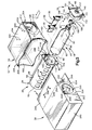
- the end cap 26 is preferably formed of the same material of which the diffuser 20 is formed. As shown in Figs. 3 and 6, the end cap 26 includes a flange 140 and a cylindrical body 142 projecting from the flange 140. An annular inner edge surface 146 of the flange 140 defines a circular access opening 148 extending through the center of the flange 140. The access opening 148 provides access to the electrical contact pins 52, as shown in Figs. 1 and 2. An annular inner side surface 149 (Fig. 6) of the flange 140 surrounds the access opening 148. The flange 140 further has a peripheral edge surface 150 with a contour closely matching the contour of the peripheral edge surface 110 of the first end wall 90 of the diffuser 20.
- the cylindrical body 142 of the end cap 26 has a cylindrical outer surface 156 with a diameter nearly equal to the full diameter D 2 (Fig. 5) of the cylindrical portion 102 of the chamber 94 in the diffuser 20.
- a cylindrical inner surface 158 of the body 142 extends inward from an open end 160 of the body 142.
- the body 142 further has a pair of diametrically opposed flat inner surfaces 162, and an adjoining pair of diametrically opposed arcuate inner surfaces 164, with one of each being visible in Fig. 6.
- the inner surfaces 162 and 164 extend from the flange 140 toward the open end 160 of the body 142.
- Another arcuate inner surface 166 extends from the adjoining pairs of inner surfaces 162 and 164 to the cylindrical inner surface 158.
- the arcuate inner surface 166 has a concave contour facing outward toward the open end 160.
- annular elastomeric seal 180 is receivable in the cylindrical body 142 of the end cap 26.
- the seal 180 has a pair of diametrically opposed flat outer surfaces 182, and has an adjoining pair of diametrically opposed arcuate outer surfaces 184.
- the outer surfaces 182 and 184 of the seal 180 register with the inner surfaces 162 and 164 of the end cap 26, respectively, upon insertion of the seal 180 into the body 142 of the end cap 26.
- the seal 180 further has an annular outer side surface 185 which abuts the annular inner side surface 149 of the end cap 26 when the seal 180 is received in the end cap 26, as shown in Fig. 5.
- An annular inner side surface 186 and a frustoconical inner surface 188 of the seal 180 then face toward the open end 160 of the end cap 26.
- the first and third fabric panels 190 and 194 are fastened to each other by stitches 202 at a seam 204.
- the seam 204 extends fully about the periphery of the first fabric panel 190 at one side of the third fabric panel 194.
- the second and third fabric panels 192 and 194 are similarly fastened to each other by stitches 206 at a seam 208.
- the seam 208 extends fully about the periphery of the second fabric panel 190 at the other side of the third fabric panel 194.
- the diffuser 20 (containing the fastener strip 130 and the mounting bolts 30) is moved longitudinally past the fabric panel 190 or 192 and into the compartment 196 through an incomplete seam 204 or 208 that fastens the fabric panel 190 or 192 to the third fabric panel 194.
- the mounting bolts 30 projecting from the rear end of the diffuser 20 are then received through the apertures 200 in the third fabric panel 194 so as to extend outward from the rear end portion 16 of the air bag 12, as shown in Figs. 1 and 2.
- the cover 28 in the preferred embodiment of the invention is shaped as a rectangular box.
- a closure wall 240 of the cover 28 closes the forward end of the cover 28.
- An opening 242 and a pair of closure flaps 244 are located at the rear end of the cover 28.
- the folded air bag 12, with the diffuser 20 contained in the compartment 196, is moved to into the cover 28 through the opening 242 at the rear end of the cover 28.
- the forward end portion 14 of the air bag 12 is then located adjacent to the closure wall 240 at the forward end of the cover 28.
- the closure flaps 244 are then folded pivotally about hinge lines 246 to close the opening 242.
- Screw threaded fasteners or the like could be used in place of the deformable fastener pins 112.
- the flange 140 on the end cap 26 then overlies a portion of the side wall 252 of the cover 28 which surrounds the opening 250, and also overlies an adjacent portion of the first fabric panel 190 which surrounds the opening 198.
- the end cap 26 thus clamps those portions of the cover 28 and the air bag 12 firmly between the flange 140 and the first end wall 90 of the diffuser 20. In this manner the end cap 26 blocks the flow of inflation fluid outward from the compartment 196 in the air bag 12 through the openings 116, 198 and 250.
Landscapes
- Engineering & Computer Science (AREA)
- Mechanical Engineering (AREA)
- Physics & Mathematics (AREA)
- Fluid Mechanics (AREA)
- Air Bags (AREA)
- Yarns And Mechanical Finishing Of Yarns Or Ropes (AREA)
Claims (19)
- Vorrichtung (10), die folgendes aufweist:wobei die Tragmittel eine Endkappe (26) und Mittel (112) aufweisen zum Befestigen der Endkappe (26) an dem ersten Endteil der Diffusorstruktur (20) in einer befestigten Position, in der die Endkappe (26) eine axial gerichtete Tragkraft auf die Aufblasmittel (18) ausübt, wobei die Tragkraft die Aufblasmittel an einem ersten Endteil (90) der Diffusorstruktur axial nach innen zu der Kammer (94) drückt und an dem zweiten Endteil (92) der Diffusorstruktur axial nach außen aus der Kammer drückt.Eine aufblasbare Fahrzeuginsassenrückhaltevorrichtung (12);Aufblasmittel (18) zum Vorsehen von Aufblasströmungsmittel zum Aufblasen der Rückhaltevorrichtung, wobei die Aufblasmittel (18) eine Achse (62), einen ersten axialen Endteil (64), einen zweiten axialen Endteil (66) und mindestens eine Strömungsmittelauslaßöffnung aufweisen;eine Diffusorstruktur (20) mit ersten (90) und zweiten (92) Endteilen, wobei die Diffusorstruktur eine Kammer (94) definiert, die sich von dem ersten Endteil (90) der Diffusorstruktur zu dem zweiten Endteil (92) der Diffusorstruktur erstreckt, wobei die Diffusorstruktur ferner Strömungsmittelauslaßmittel (104) aufweist zum Leiten des Aufblasströmungsmittels, so daß es aus der Kammer (94) ausströmt; undTragmittel zum Tragen der Aufblasmittel (18) in der Kammer (94), wobei der erste axiale Endteil (64) der Aufblasmittel an dem ersten Endteil (90) der Diffusorstruktur getragen wird und wobei der zweite axiale Endteil (66) der Aufblasmittel an dem zweiten Endteil (92) der Diffusorstruktur getragen ist;
- Vorrichtung nach Anspruch 1, wobei die Aufblasmittel (18) axial in die Kammer (94) bewegbar sind, und zwar in eine Richtung, die sich von dem ersten Endteil (90) der Diffusorstruktur zu dem zweiten Endteil (92) der Diffusorstruktur erstreckt, wobei die Endkappe (26) in die befestigte Position in die Richtung bewegbar ist, wobei die Endkappe (26) eine Oberfläche aufweist, die in die Richtung weist und welche die Tragkraft gegen den ersten axialen Endteil (64) der Aufblasmittel richtet bei einer solchen Bewegung der Endkappe (26) in die befestigte Position.
- Vorrichtung nach Anspruch 1 oder 2, wobei die Aufblasmittel (18) ein elektrisches Kontaktglied (52) an dem ersten axialen Endteil (64) aufweisen, wobei die Endkappe (26) Mittel aufweist zum Definieren einer Öffnung (148), die sich durch die Endkappe erstreckt, um einen Zugriff auf das elektrische Kontaktglied (52) vorzusehen.
- Vorrichtung nach Anspruch 1, wobei die Aufblasmittel eine erste flache Oberfläche (82) in einer Ebene aufweisen, die radial von der Achse (62) beabstandet ist, wobei die Endkappe (26) eine zweite flache Oberfläche (174) aufweist, die an der ersten flachen Oberfläche anliegt, um die Aufblasmittel in einer vorbestimmten Drehposition bezüglich der Diffusorstruktur (20) zu halten, wenn die Endkappe in der befestigten Position ist.
- Vorrichtung nach Anspruch 1, wobei die Endkappe (26) Oberflächenmittel (158) aufweist zum Umlenken des Aufblasströmungsmittels von der Endkappe zu den Strömungsmittelauslaßmitteln (104).
- Vorrichtung nach Anspruch 5, wobei die Oberflächenmittel (158) einen Oberflächenteil der Endkappe (26) aufweisen, der sich axial über die Aufblasmittel (18) erstreckt, und zwar an einer Stelle radial nach außen beabstandet von der Strömungsmittelauslaßöffnung (84), wenn sich die Endkappe in der befestigten Position befindet.
- Vorrichtung nach Anspruch 5 oder 6, wobei die Oberflächenmittel (158) einen Oberflächenteil der Endkappe (26) mit einer konkaven Kontur aufweisen, die nach innen zu der Kammer (94) weist, wenn die Endkappe in der befestigten Position ist.
- Vorrichtung nach Anspruch 1, wobei die Aufblasmittel (18) axial in die Kammer (94) bewegbar sind, und zwar von dem ersten Endteil (90) der Diffusorstruktur (20) zu dem zweiten Endteil (92) der Diffusorstruktur, wobei die Tragmittel Mittel (120) aufweisen zum Ineingriffkommen mit dem zweiten axialen Endteil (66) der Aufblasmittel, um eine solche Bewegung der Aufblasmittel in die Kammer (94) zu führen.
- Vorrichtung nach Anspruch 8, wobei der zweite Endteil (92) der Diffusorstruktur (20) eine Endwand (92) aufweist, die sich quer über die Kammer (94) erstreckt, wobei die Mittel (120) zum Ineingriffkommen mit dem zweiten Endteil der Aufblasmittel eine Vielzahl von Rippen (120) aufweist, die radial nach innen in die Kammer (94) vorragen, wobei die Rippen (120) in einer Richtung, die sich von der Endwand (92) zu dem ersten Endteil (90) der Diffusorstruktur erstreckt, langgestreckt sind.
- Vorrichtung nach Anspruch 1, wobei die Diffusorstruktur (20) ferner Mittel aufweist zum Schließen der Kammer an dem zweiten Endteil der Diffusorstruktur, um zu verhindern, daß Aufblasströmungsmittel aus der Kammer (94) in einer Richtung nach außen an dem zweiten Endteil der Diffusorstruktur vorbei austritt.
- Vorrichtung nach Anspruch 10, wobei die Mittel zum Schließen der Kammer eine Endwand (92) der Diffusorstruktur (20) umfaßt, wobei sich die Endwand vollständig kontinuierlich quer über die Kammer (94) erstreckt, um die Kammer vollständig über die Kammer hinweg zu schließen.
- Vorrichtung nach Anspruch 1, wobei die Diffusorstruktur (20) eine Wand (24) eines rohrförmigen Körpers aufweist, die die Kammer (94) definiert, wobei die Wand des rohrförmigen Körpers eine Vielzahl von Öffnungen (108, 108') aufweist, wobei die Vorrichtung ferner Anbringungsmittel aufweist zum Anbringen der Diffusorstruktur in einem Fahrzeug, wobei die Anbringungsmittel eine Vielzahl von Befestigern (30) umfassen, die jeweils von einem Befestigerstreifen (130) vorragen, der in der Kammer (94) in einer Position aufnehmbar ist, in der sich die Befestiger nach außen aus der Kammer durch die Öffnungen (108, 108') in der Wand des rohrförmigen Körpers erstrecken.
- Vorrichtung nach Anspruch 12, wobei die aufblasbare Fahrzeuginsassenrückhaltevorrichtung (12) eine Vielzahl von Stoff oder Gewebebahnen (190, 192, 194) aufweist, die aneinander an Nähten befestigt sind, um einen Endteil (16) der Rückhaltevorrichtung zu definieren, in dem die Diffusorstruktur (20) aufnehmbar ist, wobei eine der Gewebebahnen (194) sich nahtlos um die Diffusorstruktur herum erstreckt und eine Vielzahl von Öffnungen (200) aufweist zum Aufnehmen der Befestiger (30), wenn die Diffusorstruktur in dem Endteil der Rückhaltevorrichtung aufgenommen ist.
- Vorrichtung nach Anspruch 1, wobei die aufblasbare Fahrzeuginsassenrückhaltevorrichtung (12) ein Gewebebahnteil (190) aufweist, der eine Öffnung (198) definiert, durch die die Aufblasmittel (18) axial in die Rückhaltevorrichtung (12) bewegbar sind, wobei der Gewebebahnteil der Rückhaltevorrichtung zwischen die Endkappe (26) und die Diffusorstruktur (20) um den Umfang der Öffnung (198) geklemmt ist, wenn die Endkappe sich in der befestigten Position befindet.
- Vorrichtung nach Anspruch 1, wobei die Aufblasmittel (18) ein Druckgefäß (22) aufweisen, daß ein unter Druck stehendes Aufblasströmungsmittel enthält.
- Vorrichtung nach Anspruch 1, wobei die Rückhaltevorrichtung (12) Mittel aufweist zum Definieren eines Abteils oder Raums (196) innerhalb der Rückhaltevorrichtung, in dem die Aufblasmittel (18) und die Diffusorstruktur (20) enthalten sind.
- Vorrichtung nach Anspruch 16, wobei die Vorrichtung ferner eine Abdeckung (28) aufweist, die die Rückhaltevorrichtung (12), die Aufblasmittel (18) und die Diffusorstruktur (20) enthält.
- Vorrichtung nach Anspruch 17, wobei die Abdeckung (28) und die Rückhaltevorrichtung (12) an der Diffusorstruktur (20) befestigt sind.
- Vorrichtung nach Anspruch 16, wobei die Aufblasmittel (18) axial in die Kammer (94) in einer Richtung bewegbar sind, die sich von dem ersten Endteil (90) der Diffusorstruktur (20) zu dem zweiten Endteil (92) der Diffusorstruktur erstreckt, wenn die Diffusorstruktur in dem Abteil (196) innerhalb der Rückhaltevorrichtung angeordnet ist, wobei die Endkappe (26) in die befestigte Position in die Richtung bewegbar ist, wobei die Endkappe eine Oberfläche (158) aufweist, die in die Richtung weist und die die Tragkraft gegen den ersten axialen Endteil (64) der Aufblasmittel leitet bei einer solchen Bewegung der Endkappe in die befestigte Position.
Applications Claiming Priority (2)
| Application Number | Priority Date | Filing Date | Title |
|---|---|---|---|
| US259298 | 1994-06-13 | ||
| US08/259,298 US5468012A (en) | 1994-06-13 | 1994-06-13 | Air bag module |
Publications (2)
| Publication Number | Publication Date |
|---|---|
| EP0687597A1 EP0687597A1 (de) | 1995-12-20 |
| EP0687597B1 true EP0687597B1 (de) | 2000-05-24 |
Family
ID=22984369
Family Applications (1)
| Application Number | Title | Priority Date | Filing Date |
|---|---|---|---|
| EP95109060A Expired - Lifetime EP0687597B1 (de) | 1994-06-13 | 1995-06-12 | Luftsackmodul |
Country Status (10)
| Country | Link |
|---|---|
| US (1) | US5468012A (de) |
| EP (1) | EP0687597B1 (de) |
| JP (1) | JP2667964B2 (de) |
| KR (1) | KR0183180B1 (de) |
| AT (1) | ATE193253T1 (de) |
| CA (1) | CA2150443C (de) |
| CZ (1) | CZ152695A3 (de) |
| DE (1) | DE69517092T2 (de) |
| NO (1) | NO952306L (de) |
| PL (1) | PL176517B1 (de) |
Families Citing this family (51)
| Publication number | Priority date | Publication date | Assignee | Title |
|---|---|---|---|---|
| US5498030A (en) * | 1995-03-28 | 1996-03-12 | General Motors Corporation | Air bag module |
| US5582422A (en) * | 1995-03-29 | 1996-12-10 | Trw Vehicle Safety Systems Inc. | Inflator mounting structure |
| FR2737493B1 (fr) * | 1995-08-04 | 1997-08-29 | Livbag Snc | Generateur pyrotechnique de gaz chauds pour coussin lateral de protection |
| US5951038A (en) * | 1995-08-11 | 1999-09-14 | Denso Corporation | Air bag device having inner and outer bags for selectively directed expansion thereof |
| US5566973A (en) * | 1995-10-04 | 1996-10-22 | Morton International, Inc. | Advanced passenger inflator with slide in attachment to extruded module |
| US5667241A (en) * | 1995-10-17 | 1997-09-16 | Morton International, Inc. | Seat mounted side impact airbags |
| US5568936A (en) * | 1995-11-08 | 1996-10-29 | Morton International, Inc. | Airbag module case for side impact airbag module |
| JPH09142243A (ja) * | 1995-11-20 | 1997-06-03 | Honda Motor Co Ltd | 乗員保護用エアバッグ装置 |
| US5611563A (en) * | 1996-01-05 | 1997-03-18 | Morton International, Inc. | Airbag inflator attachment with snap-in sleeve |
| US5671945A (en) * | 1996-01-26 | 1997-09-30 | General Motors Corporation | Air bag assembly with diffuser |
| US5615913A (en) * | 1996-02-06 | 1997-04-01 | Morton International, Inc. | Hybrid inflator with integral diffuser |
| US5918898A (en) * | 1996-02-15 | 1999-07-06 | Trw Vehicle Safety Systems Inc. | Side impact air bag module |
| DE19610529A1 (de) * | 1996-03-18 | 1997-09-25 | Opel Adam Ag | Anordnung eines Beifahrer-Airbags |
| US5690354A (en) * | 1996-03-19 | 1997-11-25 | General Motors Corporation | Air bag module |
| JPH09323605A (ja) * | 1996-03-27 | 1997-12-16 | Morton Internatl Inc | 自動車の乗客室内の占有者を保護する方法とエアバッグクッションを折りたたむ方法 |
| US5613704A (en) * | 1996-04-22 | 1997-03-25 | Trw Vehicle Safety Systems Inc. | Diffuser structure for clamping an inflator in an air bag module |
| DE19616940C1 (de) * | 1996-04-27 | 1997-07-24 | Mst Automotive Gmbh | Beifahrer-Airbag-Modul |
| US6425601B1 (en) | 1996-06-03 | 2002-07-30 | Universal Propulsion Company, Inc. | Air bag module |
| JP2000511489A (ja) * | 1996-06-03 | 2000-09-05 | ユニヴァーサル プロパルション コムパニー インコーポレイテッド | 側面衝突エアバッグ装置 |
| JP2957479B2 (ja) * | 1996-07-17 | 1999-10-04 | 群馬日本電気株式会社 | 擬視判読装置 |
| US5687988A (en) * | 1996-07-17 | 1997-11-18 | Morton International, Inc. | Airbag cushion and airbag inflator retention device |
| US5810386A (en) * | 1996-07-23 | 1998-09-22 | Trw Vehicle Safety Systems Inc. | Sealing ring for vehicle occupant protection apparatus |
| DE29613269U1 (de) * | 1996-07-31 | 1996-11-28 | Trw Occupant Restraint Systems Gmbh, 73551 Alfdorf | Gassack-Modul für ein Fahrzeuginsassen-Rückhaltesystem |
| US5823566A (en) * | 1996-10-16 | 1998-10-20 | Alliedsignal Inc. | Air bag module with deployment flap |
| DE19642964A1 (de) * | 1996-10-18 | 1998-04-23 | Happich Gmbh Gebr | Airbagvorrichtung |
| DE19648137C2 (de) * | 1996-11-21 | 2001-10-18 | Opel Adam Ag | Airbagmodul |
| DE19705830C1 (de) * | 1997-02-15 | 1998-08-20 | Mst Automotive Gmbh | Beifahrer-Airbagmodul |
| DE19705829C1 (de) * | 1997-02-15 | 1998-05-20 | Mst Automotive Gmbh | Flexibler Airbag-Behälter |
| US5799969A (en) * | 1997-03-18 | 1998-09-01 | Trw Inc. | Vehicle occupant protection apparatus |
| US5897134A (en) * | 1997-06-13 | 1999-04-27 | Trw Vehicle Safety Systems Inc. | Vehicle occupant protection apparatus |
| US5947510A (en) * | 1998-05-08 | 1999-09-07 | Breed Automotive Technology, Inc. | Air bag module |
| EP1188624A4 (de) | 2000-04-25 | 2005-06-08 | Toyoda Gosei Kk | Gassackmodul |
| US7032925B2 (en) | 2001-12-14 | 2006-04-25 | Daicel Chemical Industries, Ltd. | Rupturable plate for inflator |
| JP2003182506A (ja) * | 2001-12-14 | 2003-07-03 | Daicel Chem Ind Ltd | インフレータ用破裂板 |
| US6976700B2 (en) * | 2002-11-12 | 2005-12-20 | Trw Vehicle Safety Systems Inc. | Air bag inflator bracket |
| US6846005B2 (en) * | 2002-12-09 | 2005-01-25 | Key Safety Systems, Inc. | Air bag cushion and module |
| US7374198B2 (en) * | 2004-04-02 | 2008-05-20 | Toyoda Gosei Co., Ltd | Airbag module canister |
| DE102006031117B4 (de) * | 2006-07-05 | 2017-07-06 | Lear Corp. | Verfahren zum Zusammenbau einer Airbag-Baugruppe und Airbag-Baugruppe |
| EP1911636A1 (de) * | 2006-10-09 | 2008-04-16 | Key Safety Systems, Inc. | Airbag gasgenerator mit Strömungsdiffusorschild |
| DE102007046227A1 (de) | 2007-01-19 | 2008-07-24 | Johnson Controls Gmbh | Gleichstrommotor in Kompaktbauweise |
| US8052167B2 (en) * | 2007-06-22 | 2011-11-08 | Tk Holdings Inc. | Airbag assembly |
| WO2009029203A1 (en) * | 2007-08-27 | 2009-03-05 | Key Safety Systems, Inc. | Knee airbag module |
| DE102007046824A1 (de) * | 2007-09-26 | 2009-04-09 | Takata-Petri Ag | Aufblaseinrichtung für ein Airbagmodul |
| KR101782076B1 (ko) * | 2008-09-30 | 2017-09-26 | 티알더블유 에어백 시스템즈 게엠베하 | 가스 발생기, 가스 발생기 제조 방법 및 가스 발생기를 구비하는 모듈 |
| US20100181746A1 (en) * | 2009-01-16 | 2010-07-22 | Rose Larry D | Airbag module housing |
| US7966920B2 (en) * | 2009-02-04 | 2011-06-28 | Toyota Motor Engineering & Manufacturing North America, Inc. | Airbag deployment and disposal devices and methods |
| DE102010012136B4 (de) * | 2010-03-20 | 2015-12-31 | Volkswagen Ag | Vorrichtung, insbesondere Schusskanalmodul, zur Befestigung eines Airbagmoduls |
| DE102010052782A1 (de) * | 2010-11-30 | 2012-05-31 | Trw Automotive Gmbh | Fahrzeuginsassenrückhaltesystem für ein Fahrzeug und Dichtungselement |
| DE102012019628B4 (de) * | 2012-10-06 | 2017-03-23 | Autoliv Development Ab | Gassackmodul für ein Kraftfahrzeug |
| DE102014005099B4 (de) | 2014-04-08 | 2019-07-11 | Autoliv Development Ab | Verfahren zum Montieren eines Airbagmoduls und Airbagmodul |
| US10518736B2 (en) | 2017-11-02 | 2019-12-31 | The Boeing Company | Thrust neutral inflation assembly and methods of use |
Family Cites Families (16)
| Publication number | Priority date | Publication date | Assignee | Title |
|---|---|---|---|---|
| US4153273A (en) * | 1978-04-14 | 1979-05-08 | General Motors Corporation | Occupant restraint cushion system |
| US4191392A (en) * | 1978-08-24 | 1980-03-04 | General Motors Corporation | Occupant restraint cushion system |
| US4964654A (en) * | 1989-05-11 | 1990-10-23 | Allied-Signal Inc. | Air bag assembly |
| US5062664A (en) * | 1989-05-11 | 1991-11-05 | Allied-Signal Inc. | Air bag assembly |
| US5069480A (en) * | 1989-05-31 | 1991-12-03 | Allied-Signal Inc. | Air bag retainer assembly |
| US5031932A (en) * | 1990-04-05 | 1991-07-16 | Frantom Richard L | Single pyrotechnic hybrid inflator |
| US5149130A (en) * | 1991-05-28 | 1992-09-22 | General Motors Corporation | Liner for inflatable occupant restraint cushion |
| WO1993008042A1 (en) * | 1991-10-21 | 1993-04-29 | Trw Vehicle Safety Systems Inc. | Airbag assembly |
| US5257815A (en) * | 1991-10-21 | 1993-11-02 | Trw Vehicle Safety Systems Inc. | Inflator mounting system |
| US5332256A (en) * | 1992-02-24 | 1994-07-26 | Morton International, Inc. | Continuous circumference diffuser reaction canister |
| US5234227A (en) * | 1992-03-02 | 1993-08-10 | General Motors Corporation | Mounting for air bag assembly |
| JP2812076B2 (ja) * | 1992-06-11 | 1998-10-15 | 池田物産株式会社 | エアバッグ装置 |
| JP2580938B2 (ja) * | 1992-09-09 | 1997-02-12 | 池田物産株式会社 | エアバッグ装置 |
| DE4241221A1 (de) * | 1992-12-08 | 1994-06-09 | Dynamit Nobel Ag | Flüssiggasgenerator für ein aufblasbares Aufprallschutzkissen zum Schutz eines Kraftfahrzeug-Insassen vor Verletzungen |
| US5356175A (en) * | 1993-07-02 | 1994-10-18 | Morton International, Inc. | Anti-rattle and retention structure for a flangeless inflator of an airbag restraint assembly |
| US5441705A (en) * | 1994-03-14 | 1995-08-15 | Morton International, Inc. | Combined reaction can and inflator with extruded generant |
-
1994
- 1994-06-13 US US08/259,298 patent/US5468012A/en not_active Expired - Fee Related
-
1995
- 1995-05-29 CA CA002150443A patent/CA2150443C/en not_active Expired - Fee Related
- 1995-06-08 KR KR1019950015026A patent/KR0183180B1/ko not_active Expired - Fee Related
- 1995-06-12 EP EP95109060A patent/EP0687597B1/de not_active Expired - Lifetime
- 1995-06-12 DE DE69517092T patent/DE69517092T2/de not_active Expired - Fee Related
- 1995-06-12 NO NO952306A patent/NO952306L/no not_active Application Discontinuation
- 1995-06-12 PL PL95309079A patent/PL176517B1/pl unknown
- 1995-06-12 AT AT95109060T patent/ATE193253T1/de not_active IP Right Cessation
- 1995-06-13 JP JP7146380A patent/JP2667964B2/ja not_active Expired - Lifetime
- 1995-06-13 CZ CZ951526A patent/CZ152695A3/cs unknown
Also Published As
| Publication number | Publication date |
|---|---|
| KR0183180B1 (ko) | 1999-05-01 |
| DE69517092T2 (de) | 2001-02-15 |
| JPH082366A (ja) | 1996-01-09 |
| NO952306L (no) | 1995-12-14 |
| JP2667964B2 (ja) | 1997-10-27 |
| ATE193253T1 (de) | 2000-06-15 |
| DE69517092D1 (de) | 2000-06-29 |
| PL309079A1 (en) | 1995-12-27 |
| EP0687597A1 (de) | 1995-12-20 |
| CA2150443C (en) | 1998-11-24 |
| CA2150443A1 (en) | 1995-12-14 |
| NO952306D0 (no) | 1995-06-12 |
| CZ152695A3 (en) | 1996-01-17 |
| US5468012A (en) | 1995-11-21 |
| KR960000643A (ko) | 1996-01-25 |
| PL176517B1 (pl) | 1999-06-30 |
Similar Documents
| Publication | Publication Date | Title |
|---|---|---|
| US5468012A (en) | Air bag module | |
| KR960002429B1 (ko) | 팽창가능한 자동차용 안전장치 | |
| US5615910A (en) | Apparatus for restraining a driver of a vehicle | |
| US6082765A (en) | Air bag module with fluid venting | |
| US5639112A (en) | Air bag module | |
| US5667241A (en) | Seat mounted side impact airbags | |
| US5810390A (en) | Module case for side impact airbag module | |
| US5588667A (en) | Vehicle occupant restraint apparatus and method of assembly | |
| EP0812740B1 (de) | Gerichtete Druckgas-Aufblasvorrichtung | |
| US5685558A (en) | Air bag inflator mounting | |
| US6250665B1 (en) | Retainer structure for an inflatable vehicle occupant protection device | |
| US5441299A (en) | Air bag inflator subassembly for installation onto the dashboard substrate of a motor vehicle | |
| US5503429A (en) | Vehicle occupant restraint apparatus and method of assembly | |
| US5738366A (en) | Chute structure for an inflatable vehicle occupant restraint | |
| EP0668196B1 (de) | Rückhaltevorrichtung für Fahrzeuginsassen | |
| US5876058A (en) | Air bag module | |
| US5673930A (en) | Vehicle occupant protection apparatus | |
| US5782481A (en) | Vehicle occupant protection apparatus | |
| US5799969A (en) | Vehicle occupant protection apparatus | |
| US6164684A (en) | Fastening structure for interconnecting parts of a vehicle occupant protection apparatus | |
| US5662351A (en) | Air bag deployment door | |
| US6017055A (en) | Vehicle occupant protection apparatus | |
| US5458363A (en) | Cylindrical inflator retainer ring | |
| US5609355A (en) | Deployment apparatus for an inflatable vehicle occupant restraint | |
| JP3424394B2 (ja) | エアバッグ装置 |
Legal Events
| Date | Code | Title | Description |
|---|---|---|---|
| PUAI | Public reference made under article 153(3) epc to a published international application that has entered the european phase |
Free format text: ORIGINAL CODE: 0009012 |
|
| 17P | Request for examination filed |
Effective date: 19950612 |
|
| AK | Designated contracting states |
Kind code of ref document: A1 Designated state(s): AT BE CH DE DK ES FR GB GR IE IT LI LU MC NL PT SE |
|
| 17Q | First examination report despatched |
Effective date: 19980414 |
|
| GRAG | Despatch of communication of intention to grant |
Free format text: ORIGINAL CODE: EPIDOS AGRA |
|
| GRAG | Despatch of communication of intention to grant |
Free format text: ORIGINAL CODE: EPIDOS AGRA |
|
| GRAH | Despatch of communication of intention to grant a patent |
Free format text: ORIGINAL CODE: EPIDOS IGRA |
|
| GRAH | Despatch of communication of intention to grant a patent |
Free format text: ORIGINAL CODE: EPIDOS IGRA |
|
| GRAA | (expected) grant |
Free format text: ORIGINAL CODE: 0009210 |
|
| AK | Designated contracting states |
Kind code of ref document: B1 Designated state(s): AT BE CH DE DK ES FR GB GR IE IT LI LU MC NL PT SE |
|
| PG25 | Lapsed in a contracting state [announced via postgrant information from national office to epo] |
Ref country code: NL Free format text: LAPSE BECAUSE OF FAILURE TO SUBMIT A TRANSLATION OF THE DESCRIPTION OR TO PAY THE FEE WITHIN THE PRESCRIBED TIME-LIMIT Effective date: 20000524 Ref country code: LI Free format text: LAPSE BECAUSE OF FAILURE TO SUBMIT A TRANSLATION OF THE DESCRIPTION OR TO PAY THE FEE WITHIN THE PRESCRIBED TIME-LIMIT Effective date: 20000524 Ref country code: IT Free format text: LAPSE BECAUSE OF FAILURE TO SUBMIT A TRANSLATION OF THE DESCRIPTION OR TO PAY THE FEE WITHIN THE PRESCRIBED TIME-LIMIT;WARNING: LAPSES OF ITALIAN PATENTS WITH EFFECTIVE DATE BEFORE 2007 MAY HAVE OCCURRED AT ANY TIME BEFORE 2007. THE CORRECT EFFECTIVE DATE MAY BE DIFFERENT FROM THE ONE RECORDED. Effective date: 20000524 Ref country code: GR Free format text: LAPSE BECAUSE OF NON-PAYMENT OF DUE FEES Effective date: 20000524 Ref country code: FR Free format text: LAPSE BECAUSE OF FAILURE TO SUBMIT A TRANSLATION OF THE DESCRIPTION OR TO PAY THE FEE WITHIN THE PRESCRIBED TIME-LIMIT Effective date: 20000524 Ref country code: ES Free format text: THE PATENT HAS BEEN ANNULLED BY A DECISION OF A NATIONAL AUTHORITY Effective date: 20000524 Ref country code: CH Free format text: LAPSE BECAUSE OF FAILURE TO SUBMIT A TRANSLATION OF THE DESCRIPTION OR TO PAY THE FEE WITHIN THE PRESCRIBED TIME-LIMIT Effective date: 20000524 Ref country code: BE Free format text: LAPSE BECAUSE OF FAILURE TO SUBMIT A TRANSLATION OF THE DESCRIPTION OR TO PAY THE FEE WITHIN THE PRESCRIBED TIME-LIMIT Effective date: 20000524 Ref country code: AT Free format text: LAPSE BECAUSE OF FAILURE TO SUBMIT A TRANSLATION OF THE DESCRIPTION OR TO PAY THE FEE WITHIN THE PRESCRIBED TIME-LIMIT Effective date: 20000524 |
|
| REF | Corresponds to: |
Ref document number: 193253 Country of ref document: AT Date of ref document: 20000615 Kind code of ref document: T |
|
| REG | Reference to a national code |
Ref country code: CH Ref legal event code: EP |
|
| PG25 | Lapsed in a contracting state [announced via postgrant information from national office to epo] |
Ref country code: LU Free format text: LAPSE BECAUSE OF NON-PAYMENT OF DUE FEES Effective date: 20000612 Ref country code: IE Free format text: LAPSE BECAUSE OF NON-PAYMENT OF DUE FEES Effective date: 20000612 |
|
| REG | Reference to a national code |
Ref country code: IE Ref legal event code: FG4D |
|
| REF | Corresponds to: |
Ref document number: 69517092 Country of ref document: DE Date of ref document: 20000629 |
|
| PG25 | Lapsed in a contracting state [announced via postgrant information from national office to epo] |
Ref country code: MC Free format text: THE PATENT HAS BEEN ANNULLED BY A DECISION OF A NATIONAL AUTHORITY Effective date: 20000724 |
|
| PG25 | Lapsed in a contracting state [announced via postgrant information from national office to epo] |
Ref country code: SE Free format text: LAPSE BECAUSE OF FAILURE TO SUBMIT A TRANSLATION OF THE DESCRIPTION OR TO PAY THE FEE WITHIN THE PRESCRIBED TIME-LIMIT Effective date: 20000824 Ref country code: PT Free format text: LAPSE BECAUSE OF FAILURE TO SUBMIT A TRANSLATION OF THE DESCRIPTION OR TO PAY THE FEE WITHIN THE PRESCRIBED TIME-LIMIT Effective date: 20000824 Ref country code: GB Free format text: LAPSE BECAUSE OF NON-PAYMENT OF DUE FEES Effective date: 20000824 Ref country code: DK Free format text: LAPSE BECAUSE OF FAILURE TO SUBMIT A TRANSLATION OF THE DESCRIPTION OR TO PAY THE FEE WITHIN THE PRESCRIBED TIME-LIMIT Effective date: 20000824 |
|
| PGFP | Annual fee paid to national office [announced via postgrant information from national office to epo] |
Ref country code: DE Payment date: 20000830 Year of fee payment: 6 |
|
| EN | Fr: translation not filed | ||
| NLV1 | Nl: lapsed or annulled due to failure to fulfill the requirements of art. 29p and 29m of the patents act | ||
| REG | Reference to a national code |
Ref country code: CH Ref legal event code: PL |
|
| PLBE | No opposition filed within time limit |
Free format text: ORIGINAL CODE: 0009261 |
|
| STAA | Information on the status of an ep patent application or granted ep patent |
Free format text: STATUS: NO OPPOSITION FILED WITHIN TIME LIMIT |
|
| REG | Reference to a national code |
Ref country code: IE Ref legal event code: MM4A |
|
| GBPC | Gb: european patent ceased through non-payment of renewal fee |
Effective date: 20000824 |
|
| 26N | No opposition filed | ||
| PG25 | Lapsed in a contracting state [announced via postgrant information from national office to epo] |
Ref country code: DE Free format text: LAPSE BECAUSE OF NON-PAYMENT OF DUE FEES Effective date: 20020403 |