EP0687630A1 - Article en matière plastique moulé par injection - Google Patents
Article en matière plastique moulé par injection Download PDFInfo
- Publication number
- EP0687630A1 EP0687630A1 EP95108456A EP95108456A EP0687630A1 EP 0687630 A1 EP0687630 A1 EP 0687630A1 EP 95108456 A EP95108456 A EP 95108456A EP 95108456 A EP95108456 A EP 95108456A EP 0687630 A1 EP0687630 A1 EP 0687630A1
- Authority
- EP
- European Patent Office
- Prior art keywords
- plastic part
- part according
- handle
- plastic
- thick
- Prior art date
- Legal status (The legal status is an assumption and is not a legal conclusion. Google has not performed a legal analysis and makes no representation as to the accuracy of the status listed.)
- Granted
Links
- 239000004033 plastic Substances 0.000 title claims description 73
- 238000001746 injection moulding Methods 0.000 title claims description 8
- 238000002347 injection Methods 0.000 claims abstract description 21
- 239000007924 injection Substances 0.000 claims abstract description 21
- 239000007787 solid Substances 0.000 claims abstract description 13
- 239000000463 material Substances 0.000 claims description 41
- 238000009825 accumulation Methods 0.000 claims description 11
- 239000007788 liquid Substances 0.000 claims description 8
- 238000001816 cooling Methods 0.000 claims description 7
- 238000002844 melting Methods 0.000 claims description 7
- 230000008018 melting Effects 0.000 claims description 7
- 230000007704 transition Effects 0.000 claims description 6
- 238000009423 ventilation Methods 0.000 claims description 4
- 235000013361 beverage Nutrition 0.000 claims description 2
- 239000011343 solid material Substances 0.000 claims description 2
- 230000035508 accumulation Effects 0.000 description 9
- 230000002349 favourable effect Effects 0.000 description 3
- 238000004519 manufacturing process Methods 0.000 description 2
- 239000011324 bead Substances 0.000 description 1
- 238000004140 cleaning Methods 0.000 description 1
- 230000003670 easy-to-clean Effects 0.000 description 1
- 238000010438 heat treatment Methods 0.000 description 1
- 238000007373 indentation Methods 0.000 description 1
- 239000000155 melt Substances 0.000 description 1
- 238000000034 method Methods 0.000 description 1
- 239000002991 molded plastic Substances 0.000 description 1
- 230000002028 premature Effects 0.000 description 1
- 230000002035 prolonged effect Effects 0.000 description 1
- 230000000630 rising effect Effects 0.000 description 1
- 238000000926 separation method Methods 0.000 description 1
- 238000007493 shaping process Methods 0.000 description 1
Images


Classifications
-
- B—PERFORMING OPERATIONS; TRANSPORTING
- B29—WORKING OF PLASTICS; WORKING OF SUBSTANCES IN A PLASTIC STATE IN GENERAL
- B29C—SHAPING OR JOINING OF PLASTICS; SHAPING OF MATERIAL IN A PLASTIC STATE, NOT OTHERWISE PROVIDED FOR; AFTER-TREATMENT OF THE SHAPED PRODUCTS, e.g. REPAIRING
- B29C45/00—Injection moulding, i.e. forcing the required volume of moulding material through a nozzle into a closed mould; Apparatus therefor
- B29C45/17—Component parts, details or accessories; Auxiliary operations
- B29C45/1703—Introducing an auxiliary fluid into the mould
- B29C45/1704—Introducing an auxiliary fluid into the mould the fluid being introduced into the interior of the injected material which is still in a molten state, e.g. for producing hollow articles
-
- B—PERFORMING OPERATIONS; TRANSPORTING
- B29—WORKING OF PLASTICS; WORKING OF SUBSTANCES IN A PLASTIC STATE IN GENERAL
- B29C—SHAPING OR JOINING OF PLASTICS; SHAPING OF MATERIAL IN A PLASTIC STATE, NOT OTHERWISE PROVIDED FOR; AFTER-TREATMENT OF THE SHAPED PRODUCTS, e.g. REPAIRING
- B29C45/00—Injection moulding, i.e. forcing the required volume of moulding material through a nozzle into a closed mould; Apparatus therefor
- B29C45/0046—Details relating to the filling pattern or flow paths or flow characteristics of moulding material in the mould cavity
-
- B—PERFORMING OPERATIONS; TRANSPORTING
- B65—CONVEYING; PACKING; STORING; HANDLING THIN OR FILAMENTARY MATERIAL
- B65D—CONTAINERS FOR STORAGE OR TRANSPORT OF ARTICLES OR MATERIALS, e.g. BAGS, BARRELS, BOTTLES, BOXES, CANS, CARTONS, CRATES, DRUMS, JARS, TANKS, HOPPERS, FORWARDING CONTAINERS; ACCESSORIES, CLOSURES, OR FITTINGS THEREFOR; PACKAGING ELEMENTS; PACKAGES
- B65D1/00—Rigid or semi-rigid containers having bodies formed in one piece, e.g. by casting metallic material, by moulding plastics, by blowing vitreous material, by throwing ceramic material, by moulding pulped fibrous material or by deep-drawing operations performed on sheet material
- B65D1/22—Boxes or like containers with side walls of substantial depth for enclosing contents
-
- B—PERFORMING OPERATIONS; TRANSPORTING
- B65—CONVEYING; PACKING; STORING; HANDLING THIN OR FILAMENTARY MATERIAL
- B65D—CONTAINERS FOR STORAGE OR TRANSPORT OF ARTICLES OR MATERIALS, e.g. BAGS, BARRELS, BOTTLES, BOXES, CANS, CARTONS, CRATES, DRUMS, JARS, TANKS, HOPPERS, FORWARDING CONTAINERS; ACCESSORIES, CLOSURES, OR FITTINGS THEREFOR; PACKAGING ELEMENTS; PACKAGES
- B65D25/00—Details of other kinds or types of rigid or semi-rigid containers
- B65D25/28—Handles
- B65D25/30—Hand holes
-
- B—PERFORMING OPERATIONS; TRANSPORTING
- B29—WORKING OF PLASTICS; WORKING OF SUBSTANCES IN A PLASTIC STATE IN GENERAL
- B29L—INDEXING SCHEME ASSOCIATED WITH SUBCLASS B29C, RELATING TO PARTICULAR ARTICLES
- B29L2031/00—Other particular articles
- B29L2031/712—Containers; Packaging elements or accessories, Packages
- B29L2031/7134—Crates, e.g. for bottles
Definitions
- the invention relates to an injection molded plastic part, in particular handle of a bottle crate, with a cavity created by gas injection, preferably with two superimposed, essentially horizontal cavity sections, the lower cavity section being the lower boundary of the handle.
- the invention has for its object to propose a plastic part of the type mentioned, which is equally stable and easy to grip and avoid stress cracks and the like.
- An advantageous development of the invention is characterized in that the solid web is the thinnest in its central section between the two cavity sections and is made stronger towards the two cavity sections.
- the web viewed in cross section, runs essentially straight on one of its two vertical edges and is concave on its opposite edge.
- the concave edge is provided with a constant radius of curvature.
- the web is provided with a groove by a knife-shaped part protruding from the injection mold, said groove running parallel to the cavity sections.
- the groove it is also possible for the groove to be closed after the injection molding process by melting the edges surrounding it.
- a particularly advantageous embodiment of the invention is that the two cavities lying one above the other are connected to one another at least at one end via a vertical channel.
- the two cavities can also be produced separately or parallel to one another; in an arrangement in series, however, only a single inlet opening for the compressed gas and possibly only a single outlet opening for plastic material displaced by the gas is necessary.
- This combined arrangement enables optimum conditions for the cross section in relation to the cavity length in the cavities.
- At least the closely arranged cavities in the longitudinal side handles are laterally connected to one another by vertical channels.
- the cavities lie one behind the other and can be produced in one operation.
- the grooves dividing the webs are closed after the bottle crate has been injection molded by melting the material surrounding the groove again.
- a material accumulation is provided on at least one of the mutually facing regions of the two wall sections.
- Another advantageous embodiment of the invention is that the material accumulation is provided in a recess provided in the wall area.
- the inlet point of the gaseous medium is provided at one end of one of the two cavities, while the two ends of the two cavities remote from the inlet point are connected to one another.
- the two meandering cavities are successively flowed through by the gaseous medium and thereby formed.
- the introduction point of the gaseous medium prefferably be provided at or in the vicinity of the connection point of the two cavities.
- the gaseous medium flows through and forms the two cavities almost simultaneously.
- An advantageous embodiment of the invention is that the upper thick point has a smaller cross section than the lower thick point.
- a particularly hand-friendly arrangement is thus achieved which has a very high rigidity.
- the inlet point for the gaseous medium is in the region of the thinner thick point and thus the cavity with a smaller cross section.
- the plastic cools more slowly than in the area of the thinner thick area, which is why the gaseous medium still finds sufficient liquid plastic in the thicker area even after flowing through the thinner area in order to enable the cavity to be formed properly.
- a very advantageous embodiment of the invention resides in the fact that the free cross-sections of the thin sections adjoining the cavities of the thick sections are designed in such a way that unintentional passage of the gaseous medium is excluded.
- the free cross section of the thin points adjoining cavities has a clear width of approximately 1.8 to 2.0 mm.
- a further advantageous embodiment of the invention resides in the fact that materials which have a particularly high thermal conductivity are used in the injection mold in the region of the thin spots adjoining the thick spots provided with cavities.
- a further advantageous embodiment of the invention is that the lower thick point provided with a cavity runs downward in an arc from the two ends.
- the invention further relates to a plastic part, in particular a plastic box for transporting beverage bottles with at least one handle opening and a handle arranged above it, which is formed by simultaneously injecting liquid plastic from both ends.
- this problem is solved in that the two flow channels for introducing the plastic into the handle have different free cross sections.
- a particularly advantageous embodiment of the invention resides in the fact that the handle has two thick point areas lying one above the other, each of which extends over the entire handle and both of which are supplied with liquid plastic from the two ends of the handle, and that the flow channels of the two thick point areas are provided with different free cross sections are provided.
- Ventilation openings are expediently provided for each of the thick-point regions, wherein these ventilation openings can also be arranged offset to one another.
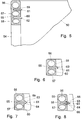
- FIG. 1 in FIG. 1 denotes a bottle crate, from whose bottom, not shown, four side walls protrude, namely two longitudinal side walls 2 and two narrow side walls 3.
- a handle opening 4 and 5 is provided, the top of a handle 6 or 7 is completed.
- the handle 7 shown in vertical section in FIG. 1 in the narrow side wall 3 has a cavity 8, 9 at the top and bottom, which are connected to one another by a solid web 10.
- an indentation 11 is provided, which is used, for example, to hold a label or an imprint.
- the inner edge 12 of the web 10 is concave, with a constant radius, the material thickness remaining in the central section being relatively small.
- the two cavities 8, 9 can be produced as individual channels, but it is also possible to arrange the two channels one behind the other, for which purpose they are connected at one end by a vertical channel (not shown). Due to the relatively thin design of the web 10, plastic material is deposited at this point when the box is sprayed, so that no unintentional connection of the two cavities can occur along their longitudinal extent.
- the long side wall 2 is provided with a handle 6, which is shown in vertical section in FIG. It has three cavities 31, 32 and 33 lying one above the other, which are separated from one another by massive webs 34 and 35, respectively. At their ends, however, these cavities 31, 32, 33 are alternately connected to one another, so that there is a meandering arrangement.
- grooves 36 and 37 provided by corresponding tool parts are provided there. These grooves can either remain open or be subsequently closed by melting the material surrounding the two webs 34 and 35.
- FIG. 4 shows an exemplary embodiment of a handle 6, in which material tips 38 which are arranged in a recessed manner on the webs 34 and 35 are formed.
- Corresponding material tips can also be provided for the web 22 in FIG. 2. However, it is also possible to provide all or part of the grooves with rounded edges and then to leave the grooves open.
- FIG. 5 is a partially illustrated bottle crate, which is provided on all four side walls with a handle opening 54 and a handle 55 arranged above it.
- the box is produced with the aid of a tool, not shown, in the injection molding process, liquid plastic being injected into the cavities of the tool.
- a tool not shown
- liquid plastic being injected into the cavities of the tool.
- Arranged within the handle 55 are three cavity sections 56, 57, 58 arranged one above the other, which are connected to one another in a manner not shown, at their respective lateral ends, in a meandering manner. Between these cavity sections 56, 57, 58, two wall sections 59 and 60, each formed in two parts, are arranged.
- Each of these wall sections 59 and 60 is divided into itself by a narrow gap 61 and 62, which can be closed after the completion by repeated local heating up beyond the melting point of the plastic.
- a material accumulation 63 in the form of a tip directed away from the handle can be provided on one of the adjacent regions of the two wall sections, which closes the gap when it is melted again.
- such material accumulations formed as tips 63, 64 can also be provided on both wall sections.
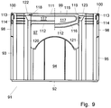
- a bottle crate is designated by 91 in FIGS. 9 and 10, which has a bottom 92 and four walls 93, 94, 95, 96 rising from it.
- a handle opening 97, 98 is recessed, which is delimited at the top by a handle 99, 100.
- Each of these four handles has two thick points 111, 112 and 113, 114, in which cavities 115, 116 are provided, which run largely horizontally and are arranged at the top and bottom of the handle edge at a distance from one another and essentially parallel to one another.
- the free cross-section of the thin-point regions 117 adjoining the cavities 115, 116 have a clear width of approximately 1.8 to 2.0 mm.
- the thick point 111, 113 arranged in the handle at the top is somewhat smaller in cross section than the lower thick point 112, 114, as a result of which the corresponding cavities are also of different sizes.
- An inlet point 118 for a gaseous medium is provided in the upper thick point 111, 113 at one end, while its end facing away from it is connected downward to the lower thick point 112, 114 (connecting channel 119).
- the gaseous medium introduced under a pressure of about 40 to 50 bar forces the plastic which is still liquid from the injection process to the outside and forms a cavity 115 which extends along the entire upper thick point 111, 113.
- the gaseous medium then reaches the lower thick point 112, 114 via the vertical connection 119 and also forms a corresponding cavity 116 there.
- the pressure of the gaseous medium is then maintained until the plastic has solidified.
- the material shrinkage that occurs when the plastic cools is compensated for by the gaseous medium flowing in, so that no shrinkage points are visible in the fully cooled and molded bottle crate 91. Due to the fact that the thin points 117 adjacent to the two cavities 115, 116 are made particularly thin, an undesired breaking through of the gaseous medium into this area is avoided. In the injection mold, materials can be provided in the areas of the adjacent thin points 117, which have a very good thermal conductivity and thus ensure rapid cooling of the plastic in this area.
- the inlet point for the gaseous medium can of course also be arranged within a vertical, hollow spar 120 or 121.
- the corresponding digits are labeled 122 and 123; no opening is visible in the finished box in the area of the handles.
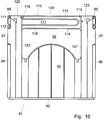
- FIG. 11 is a bottle crate, which is equipped in its four side walls 202 with a handle opening 203, which is closed at the top by a handle 204.
- the liquid plastic is injected from the bottom and fed to the handles 204 via the corner bars 205. Since the plastic is supplied simultaneously via the two corner bars 205 delimiting a handle 204, the two plastic streams meet within the handle 204, although cooling has already occurred due to the long flow path, and therefore the two streams are not completely mixed. Rather, the ends of the plastic streams largely only abut each other and inevitably result in a weak point at which the handle breaks after prolonged use of the bottle crate or under excessive load.
- cross-sectional tapers 206 and 207 are therefore provided, which force different flow rates.
- a cross-sectional taper 206 is provided for the upper thick point region 208 at the transition from the corner spar 205 shown on the left.
- the two plastic streams meet at the point labeled 210, to the left of the center of the handle.
- there is a corresponding cross-sectional taper 207 at the transition from the right lying corner pillar 205 to this thick point area 209 is provided.
- the meeting point 211 of the two plastic streams lies to the right of the center of the handle 204.
- the two weak points 210 and 211 in the region of the thick points are offset from one another to such an extent that breaking of the handle through these weak points is no longer to be feared.
- the two thick area regions 208 and 209 are each additionally provided with a cavity 212 or 213 by introducing gas or compressed air, which, however, does not affect the weak points, but effectively prevents the thick area areas from shrinking when the plastic cools.
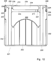
- four handles 224 are provided in a bottle crate 221, which are only equipped with a thick area 229 at their lower end, while their upper end 228 is angular. It is sufficient here if a cross-sectional taper 227 is provided on one side of the thick point region 229, in order to thereby move the meeting point 211 of the two plastic streams into the lateral edge region of the handle. This means that the unavoidable weak point has been moved to a less stressed area so that there is no fear of premature material fatigue.
- a cross-sectional taper 226 can also be provided in the upper, angularly shaped end region 228, as a result of which the meeting point 210 of the two plastic streams is also shifted from the center in this region.
- a further increase in the breaking strength of the handle can thus be achieved.
- the injection mold is provided with a ventilation opening (not shown) in this area. This vent opening can extend over the entire length of the handle; however, it can also be moved from the center of the handle to assist in moving the meeting point of the two material flows.
Landscapes
- Engineering & Computer Science (AREA)
- Mechanical Engineering (AREA)
- Manufacturing & Machinery (AREA)
- Ceramic Engineering (AREA)
- Details Of Rigid Or Semi-Rigid Containers (AREA)
- Brushes (AREA)
- Pens And Brushes (AREA)
- Containers Having Bodies Formed In One Piece (AREA)
Applications Claiming Priority (8)
| Application Number | Priority Date | Filing Date | Title |
|---|---|---|---|
| DE4421051 | 1994-06-17 | ||
| DE19944421051 DE4421051A1 (de) | 1994-06-17 | 1994-06-17 | Im Spritzgießverfahren hergestelltes Kunststoffteil |
| DE4421685 | 1994-06-24 | ||
| DE19944421685 DE4421685A1 (de) | 1994-06-24 | 1994-06-24 | Im Spritzgießverfahren hergestelltes Kunststoffteil |
| DE4436641 | 1994-10-13 | ||
| DE19944436641 DE4436641A1 (de) | 1994-10-13 | 1994-10-13 | Flaschenkasten |
| DE9418484U DE9418484U1 (de) | 1994-11-22 | 1994-11-22 | Kunststoffkasten |
| DE9418484U | 1994-11-22 |
Publications (2)
| Publication Number | Publication Date |
|---|---|
| EP0687630A1 true EP0687630A1 (fr) | 1995-12-20 |
| EP0687630B1 EP0687630B1 (fr) | 1999-08-25 |
Family
ID=27435993
Family Applications (1)
| Application Number | Title | Priority Date | Filing Date |
|---|---|---|---|
| EP95108456A Expired - Lifetime EP0687630B1 (fr) | 1994-06-17 | 1995-06-02 | Article en matière plastique moulé par injection |
Country Status (3)
| Country | Link |
|---|---|
| EP (1) | EP0687630B1 (fr) |
| AT (1) | ATE183707T1 (fr) |
| DE (1) | DE59506670D1 (fr) |
Cited By (4)
| Publication number | Priority date | Publication date | Assignee | Title |
|---|---|---|---|---|
| EP0770552A1 (fr) * | 1995-10-26 | 1997-05-02 | Wilhelm Götz | Casier à bouteilles et procédé de fabrication d'une tel casier |
| GB2383292A (en) * | 2001-12-20 | 2003-06-25 | Adrian Joseph Lloyd | Improvements relating to grab handles |
| DE10334773A1 (de) * | 2003-07-30 | 2005-03-10 | Arca Systems Gmbh | Kunststoffprodukt, insbesondere Flaschenkasten, Verfahren und Vorrichtung zur Herstellung eines Kunststoffprodukts |
| EP2664434A1 (fr) * | 2012-04-17 | 2013-11-20 | D.W. Plastics NV | Procédé de moulage par injection pour former une caisse à bouteilles, caisse à bouteilles et appareil correspondant permettant d'obtenir cette caisse à bouteilles |
Citations (5)
| Publication number | Priority date | Publication date | Assignee | Title |
|---|---|---|---|---|
| DE3940186A1 (de) * | 1989-12-05 | 1991-06-06 | Rudolf Koose | Verfahren und vorrichtung zur erzeugung von hohlen wandbereichen an kunststoffkaesten, insbesondere flaschenkaesten |
| EP0484763A2 (fr) * | 1990-11-08 | 1992-05-13 | Peguform-Werke Gmbh | Procédé et dispositif pour fabriquer des caisses de transport, notamment des caisses à bouteilles |
| EP0486107A1 (fr) * | 1990-11-14 | 1992-05-20 | Wavin B.V. | Caisse en plastique avec poignée partiellement creuse |
| EP0603531A1 (fr) * | 1992-12-23 | 1994-06-29 | Schoeller-Plast S.A. | Casier à bouteilles en matière plastique avec poignée |
| DE9418484U1 (de) * | 1994-11-22 | 1995-01-12 | Götz, Wilhelm, 88410 Bad Wurzach | Kunststoffkasten |
-
1995
- 1995-06-02 DE DE59506670T patent/DE59506670D1/de not_active Expired - Lifetime
- 1995-06-02 EP EP95108456A patent/EP0687630B1/fr not_active Expired - Lifetime
- 1995-06-02 AT AT95108456T patent/ATE183707T1/de active
Patent Citations (5)
| Publication number | Priority date | Publication date | Assignee | Title |
|---|---|---|---|---|
| DE3940186A1 (de) * | 1989-12-05 | 1991-06-06 | Rudolf Koose | Verfahren und vorrichtung zur erzeugung von hohlen wandbereichen an kunststoffkaesten, insbesondere flaschenkaesten |
| EP0484763A2 (fr) * | 1990-11-08 | 1992-05-13 | Peguform-Werke Gmbh | Procédé et dispositif pour fabriquer des caisses de transport, notamment des caisses à bouteilles |
| EP0486107A1 (fr) * | 1990-11-14 | 1992-05-20 | Wavin B.V. | Caisse en plastique avec poignée partiellement creuse |
| EP0603531A1 (fr) * | 1992-12-23 | 1994-06-29 | Schoeller-Plast S.A. | Casier à bouteilles en matière plastique avec poignée |
| DE9418484U1 (de) * | 1994-11-22 | 1995-01-12 | Götz, Wilhelm, 88410 Bad Wurzach | Kunststoffkasten |
Cited By (4)
| Publication number | Priority date | Publication date | Assignee | Title |
|---|---|---|---|---|
| EP0770552A1 (fr) * | 1995-10-26 | 1997-05-02 | Wilhelm Götz | Casier à bouteilles et procédé de fabrication d'une tel casier |
| GB2383292A (en) * | 2001-12-20 | 2003-06-25 | Adrian Joseph Lloyd | Improvements relating to grab handles |
| DE10334773A1 (de) * | 2003-07-30 | 2005-03-10 | Arca Systems Gmbh | Kunststoffprodukt, insbesondere Flaschenkasten, Verfahren und Vorrichtung zur Herstellung eines Kunststoffprodukts |
| EP2664434A1 (fr) * | 2012-04-17 | 2013-11-20 | D.W. Plastics NV | Procédé de moulage par injection pour former une caisse à bouteilles, caisse à bouteilles et appareil correspondant permettant d'obtenir cette caisse à bouteilles |
Also Published As
| Publication number | Publication date |
|---|---|
| EP0687630B1 (fr) | 1999-08-25 |
| DE59506670D1 (de) | 1999-09-30 |
| ATE183707T1 (de) | 1999-09-15 |
Similar Documents
| Publication | Publication Date | Title |
|---|---|---|
| DE68904082T2 (de) | Flaeschchenkette fuer pharmazeutische, kosmetische und andere produkte. | |
| DE60010070T2 (de) | Methode zur herstellung von laminierten flaschen mit abschälbarer innerer schicht | |
| DE69219157T2 (de) | Spritzgiessen von kunststoffgegenständen die hohlförmige rippen aufweisen | |
| DE2918926C2 (de) | Spritzgießform zum Herstellen von aus mindestens zwei verschiedenen Kunststoffmassen bestehenden und mindestens zwei unterschiedliche Bereiche aufweisenden Spritzgußteilen | |
| EP0666791B1 (fr) | Procede de moulage par injection de pieces en matiere thermoplastique et outil permettant la mise en uvre dudit procede | |
| EP0396728B2 (fr) | Casier a bouteilles en matiere plastique | |
| EP0770552B1 (fr) | Casier à bouteilles et procédé de fabrication d'une tel casier | |
| EP0687630B1 (fr) | Article en matière plastique moulé par injection | |
| DE69905786T2 (de) | Verfaren und Vorrichtung zur Herstellung eines gegossenen Flächenhaftverschlusses und so hergestellter Flächenhaftverschluss | |
| DE3900894A1 (de) | Verfahren zur herstellung von flaschenkaesten mit waagrechten griffholmen sowie entsprechende flaschenkaesten | |
| EP0401546B1 (fr) | Emballage pour produits fluides et son procédé de fabrication | |
| EP0204200B1 (fr) | Procédé et dispositif pour la fabrication par soufflage de corps creux en matière thermoplastique | |
| DE3939143C2 (fr) | ||
| DE3839087C2 (de) | Flaschenkasten aus Kunststoff sowie Verfahren zur Herstellung desselben | |
| EP0189906B1 (fr) | Outil pour le moulage de récipients superposables | |
| EP0211965B1 (fr) | Récipient en matière plastique pour liquide, notamment pour mazout, sa forme et son procédé de fabrication | |
| DE4421685A1 (de) | Im Spritzgießverfahren hergestelltes Kunststoffteil | |
| DE4334251A1 (de) | Verfahren zur Herstellung eines Anhängeelementeaufbaues | |
| EP1342546B1 (fr) | Moule d'injection avec un noyau de segments mobile | |
| DE10016973A1 (de) | Verfahren zum Herstellen eines Handgriffs, danach hergestellte Handgriffe und Flaschenkasten mit einem Handgriff | |
| EP0484763B1 (fr) | Procédé et dispositif pour fabriquer des caisses de transport, notamment des caisses à bouteilles | |
| EP0769358A2 (fr) | Procédé et installation pour insérer un boudin de matériau dans un moule | |
| EP2633968B1 (fr) | Procédé de fabrication d'un récipient en plastique et récipient en plastique | |
| DE2123331A1 (de) | Verfahren zur Herstellung einer Platte aus thermoplastischem Kunststoff in Leichtbauweise und Vorrichtung zur Durchführung dieses Verfahrens | |
| DE4436641A1 (de) | Flaschenkasten |
Legal Events
| Date | Code | Title | Description |
|---|---|---|---|
| PUAI | Public reference made under article 153(3) epc to a published international application that has entered the european phase |
Free format text: ORIGINAL CODE: 0009012 |
|
| AK | Designated contracting states |
Kind code of ref document: A1 Designated state(s): AT CH DE LI NL |
|
| RAX | Requested extension states of the european patent have changed |
Free format text: LT;SI PAYMENT 950602 |
|
| 17P | Request for examination filed |
Effective date: 19960506 |
|
| 17Q | First examination report despatched |
Effective date: 19970509 |
|
| GRAG | Despatch of communication of intention to grant |
Free format text: ORIGINAL CODE: EPIDOS AGRA |
|
| GRAG | Despatch of communication of intention to grant |
Free format text: ORIGINAL CODE: EPIDOS AGRA |
|
| GRAH | Despatch of communication of intention to grant a patent |
Free format text: ORIGINAL CODE: EPIDOS IGRA |
|
| GRAH | Despatch of communication of intention to grant a patent |
Free format text: ORIGINAL CODE: EPIDOS IGRA |
|
| GRAA | (expected) grant |
Free format text: ORIGINAL CODE: 0009210 |
|
| AK | Designated contracting states |
Kind code of ref document: B1 Designated state(s): AT CH DE LI NL |
|
| AX | Request for extension of the european patent |
Free format text: SI PAYMENT 19950602 |
|
| REF | Corresponds to: |
Ref document number: 183707 Country of ref document: AT Date of ref document: 19990915 Kind code of ref document: T |
|
| REG | Reference to a national code |
Ref country code: CH Ref legal event code: EP |
|
| REF | Corresponds to: |
Ref document number: 59506670 Country of ref document: DE Date of ref document: 19990930 |
|
| REG | Reference to a national code |
Ref country code: CH Ref legal event code: NV Representative=s name: AMMANN PATENTANWAELTE AG BERN |
|
| PLBE | No opposition filed within time limit |
Free format text: ORIGINAL CODE: 0009261 |
|
| STAA | Information on the status of an ep patent application or granted ep patent |
Free format text: STATUS: NO OPPOSITION FILED WITHIN TIME LIMIT |
|
| 26N | No opposition filed | ||
| PGFP | Annual fee paid to national office [announced via postgrant information from national office to epo] |
Ref country code: NL Payment date: 20080609 Year of fee payment: 14 |
|
| NLV4 | Nl: lapsed or anulled due to non-payment of the annual fee |
Effective date: 20100101 |
|
| PG25 | Lapsed in a contracting state [announced via postgrant information from national office to epo] |
Ref country code: NL Free format text: LAPSE BECAUSE OF NON-PAYMENT OF DUE FEES Effective date: 20100101 |
|
| PGFP | Annual fee paid to national office [announced via postgrant information from national office to epo] |
Ref country code: AT Payment date: 20110616 Year of fee payment: 17 |
|
| REG | Reference to a national code |
Ref country code: AT Ref legal event code: MM01 Ref document number: 183707 Country of ref document: AT Kind code of ref document: T Effective date: 20120602 |
|
| PG25 | Lapsed in a contracting state [announced via postgrant information from national office to epo] |
Ref country code: AT Free format text: LAPSE BECAUSE OF NON-PAYMENT OF DUE FEES Effective date: 20120602 |
|
| PGFP | Annual fee paid to national office [announced via postgrant information from national office to epo] |
Ref country code: DE Payment date: 20131118 Year of fee payment: 19 |
|
| PGFP | Annual fee paid to national office [announced via postgrant information from national office to epo] |
Ref country code: CH Payment date: 20140625 Year of fee payment: 20 |
|
| REG | Reference to a national code |
Ref country code: DE Ref legal event code: R119 Ref document number: 59506670 Country of ref document: DE |
|
| REG | Reference to a national code |
Ref country code: DE Ref legal event code: R119 Ref document number: 59506670 Country of ref document: DE Effective date: 20150101 |
|
| PG25 | Lapsed in a contracting state [announced via postgrant information from national office to epo] |
Ref country code: DE Free format text: LAPSE BECAUSE OF NON-PAYMENT OF DUE FEES Effective date: 20150101 |
|
| REG | Reference to a national code |
Ref country code: CH Ref legal event code: PL |