EP0484763A2 - Procédé et dispositif pour fabriquer des caisses de transport, notamment des caisses à bouteilles - Google Patents
Procédé et dispositif pour fabriquer des caisses de transport, notamment des caisses à bouteilles Download PDFInfo
- Publication number
- EP0484763A2 EP0484763A2 EP91118210A EP91118210A EP0484763A2 EP 0484763 A2 EP0484763 A2 EP 0484763A2 EP 91118210 A EP91118210 A EP 91118210A EP 91118210 A EP91118210 A EP 91118210A EP 0484763 A2 EP0484763 A2 EP 0484763A2
- Authority
- EP
- European Patent Office
- Prior art keywords
- injection
- box
- compressed gas
- cross
- crates
- Prior art date
- Legal status (The legal status is an assumption and is not a legal conclusion. Google has not performed a legal analysis and makes no representation as to the accuracy of the status listed.)
- Granted
Links
Images

Classifications
-
- B—PERFORMING OPERATIONS; TRANSPORTING
- B29—WORKING OF PLASTICS; WORKING OF SUBSTANCES IN A PLASTIC STATE IN GENERAL
- B29C—SHAPING OR JOINING OF PLASTICS; SHAPING OF MATERIAL IN A PLASTIC STATE, NOT OTHERWISE PROVIDED FOR; AFTER-TREATMENT OF THE SHAPED PRODUCTS, e.g. REPAIRING
- B29C45/00—Injection moulding, i.e. forcing the required volume of moulding material through a nozzle into a closed mould; Apparatus therefor
- B29C45/17—Component parts, details or accessories; Auxiliary operations
- B29C45/26—Moulds
- B29C45/27—Sprue channels ; Runner channels or runner nozzles
- B29C45/2725—Manifolds
-
- B—PERFORMING OPERATIONS; TRANSPORTING
- B29—WORKING OF PLASTICS; WORKING OF SUBSTANCES IN A PLASTIC STATE IN GENERAL
- B29C—SHAPING OR JOINING OF PLASTICS; SHAPING OF MATERIAL IN A PLASTIC STATE, NOT OTHERWISE PROVIDED FOR; AFTER-TREATMENT OF THE SHAPED PRODUCTS, e.g. REPAIRING
- B29C45/00—Injection moulding, i.e. forcing the required volume of moulding material through a nozzle into a closed mould; Apparatus therefor
- B29C45/17—Component parts, details or accessories; Auxiliary operations
- B29C45/1703—Introducing an auxiliary fluid into the mould
- B29C45/1704—Introducing an auxiliary fluid into the mould the fluid being introduced into the interior of the injected material which is still in a molten state, e.g. for producing hollow articles
-
- B—PERFORMING OPERATIONS; TRANSPORTING
- B29—WORKING OF PLASTICS; WORKING OF SUBSTANCES IN A PLASTIC STATE IN GENERAL
- B29L—INDEXING SCHEME ASSOCIATED WITH SUBCLASS B29C, RELATING TO PARTICULAR ARTICLES
- B29L2031/00—Other particular articles
- B29L2031/712—Containers; Packaging elements or accessories, Packages
- B29L2031/7134—Crates, e.g. for bottles
Definitions
- the invention relates to a method and a device for the production of transport boxes, in particular bottle boxes, in the injection molding process with injection of molten plastic at several points, preferably in the bottom area.
- Usual transport crates and here again bottle crates have long been manufactured in large numbers by injection molding from plastic.
- plastic is usually pressed into a two-part mold under high pressure from several injection points in the hot, molten state and then the cavity between the two mold halves is filled. After cooling sufficiently, the two molded parts are moved apart and the finished box can then be removed.
- the present invention is based on the object of making available a method and a device for carrying out the method, with or with which, in a simple and effective manner in the case of transport boxes and in particular bottle boxes, large-volume cross-sectional areas of the box, in particular in the area of the handles and the Corner posts can be provided with internal cavities.
- the solution to the problem is characterized in claim 1.
- a device for performing the method provides a heated injection channel distributor which, in addition to the normal injection nozzles for the plastic material, has special nozzles which open into the large-volume cross-sectional areas of the box and have injection nozzles for the central introduction of compressed gas into the plastic stream.
- the injection channel distributor is cruciform and has an injection nozzle in the bottom region of the bottle crate at the ends of the cross arms.
- the special nozzles are arranged laterally projecting at the ends of the cross arms so that they open at the bottom of the box in the bottom area of an inner rib arranged on each of the four box sides, which lead vertically and on one side of an engagement opening to a handle arranged above the opening for the box .
- a compressed gas channel leads into the area of the handle and creates an internal cavity there.
- a further vertical inner rib can also be provided on the other side of the engagement openings, which leads from the box bottom to the handle. If the process is carried out correctly, this will flow Compressed gas inside the further inner rib back towards the box bottom, so that the further inner rib also contains a cavity.
- the compressed gas can be vented at the end of the flow path for the compressed gas, for example at the lower end of the further vertical inner rib.
- the bottle crate according to FIG. 1 has in the usual way an only partially visible, ribbed bottom 1 and is divided into four compartments with the aid of two intersecting inner walls 2 for receiving a six-pack of bottles each.
- protruding spacers 3 are provided on the floor, of which only two are visible.
- the box also has corner bars 4, which are connected to one another by walls 5, in the usual way.
- engagement openings 6 are provided on all four sides of the box.
- the wall areas below the engaging openings 6 are also referred to as advertising spaces because the respective brewery and the type of beverage are usually specified here.
- handles 7 are formed by additional ribs, which because of the relatively large weight of a filled box must have both a wide contact surface for the hand and relatively high strength. Nevertheless, the box should remain as light as possible, so that not too much dead weight is transported unnecessarily and material is saved as much as possible.
- the hollow design of the handles 7, each with an inner cavity 8, is achieved in that inner stiffening ribs 9 lead from the bottom to the handle 7 on both sides of the engagement openings 7. Compressed gas flows through one of these stiffening ribs 9 together with the molten plastic to the handle 7 and forms the inner cavity 8. The compressed gas then flows further over the respective other inner rib 9 in the direction of the floor and can later be relaxed there by piercing.
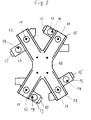
- FIG. 2 shows an injection channel distributor which is used to manufacture the bottle crate according to FIG. 1 using the injection molding process.
- the distributor 10 is heated during operation so that the plastic material supplied under high pressure in the middle area remains molten. It is then pressed into the injection mold at the bottom in a conventional manner at four injection points 11, which are arranged at the ends of the arms 12 of the cross-shaped distributor 10.
- the distributor 10 has at the ends of the arms 12 laterally arranged special nozzles 13, each of which has additional injection points 14.
- a pressure gas, preferably nitrogen, is also fed to the special nozzles via connections 15, which is then directed into the mold approximately in the central region of the plastic strand emerging from the injection points 14, namely at the lower end of one of the inner ribs 9 on each side of the box. In this way, the inner cavities are then formed in the area of the inner ribs 9 and the handles 7.
Landscapes
- Engineering & Computer Science (AREA)
- Manufacturing & Machinery (AREA)
- Mechanical Engineering (AREA)
- Details Of Rigid Or Semi-Rigid Containers (AREA)
- Containers Having Bodies Formed In One Piece (AREA)
- Refuse Collection And Transfer (AREA)
- Injection Moulding Of Plastics Or The Like (AREA)
- Rigid Containers With Two Or More Constituent Elements (AREA)
- Lubricants (AREA)
Applications Claiming Priority (2)
| Application Number | Priority Date | Filing Date | Title |
|---|---|---|---|
| DE4035497A DE4035497C2 (de) | 1990-11-08 | 1990-11-08 | Vorrichtung zur Herstellung von Transportkästen, insbesondere Flaschenkästen |
| DE4035497 | 1990-11-08 |
Publications (3)
| Publication Number | Publication Date |
|---|---|
| EP0484763A2 true EP0484763A2 (fr) | 1992-05-13 |
| EP0484763A3 EP0484763A3 (en) | 1992-08-12 |
| EP0484763B1 EP0484763B1 (fr) | 1995-01-04 |
Family
ID=6417863
Family Applications (1)
| Application Number | Title | Priority Date | Filing Date |
|---|---|---|---|
| EP91118210A Expired - Lifetime EP0484763B1 (fr) | 1990-11-08 | 1991-10-25 | Procédé et dispositif pour fabriquer des caisses de transport, notamment des caisses à bouteilles |
Country Status (3)
| Country | Link |
|---|---|
| EP (1) | EP0484763B1 (fr) |
| AT (1) | ATE116595T1 (fr) |
| DE (2) | DE4035497C2 (fr) |
Cited By (2)
| Publication number | Priority date | Publication date | Assignee | Title |
|---|---|---|---|---|
| EP0687630A1 (fr) * | 1994-06-17 | 1995-12-20 | Wilhelm Götz | Article en matière plastique moulé par injection |
| EP0770552A1 (fr) * | 1995-10-26 | 1997-05-02 | Wilhelm Götz | Casier à bouteilles et procédé de fabrication d'une tel casier |
Family Cites Families (8)
| Publication number | Priority date | Publication date | Assignee | Title |
|---|---|---|---|---|
| DE2501314A1 (de) * | 1975-01-15 | 1976-07-22 | Roehm Gmbh | Spritzgiessen hohler formteile aus thermoplastischen kunststoffen, insbesondere fuer den bausektor |
| DE2734746A1 (de) * | 1977-08-02 | 1979-02-08 | Koose Rudolf | Verteiler fuer eine kunststoffmasse |
| GB8706204D0 (en) * | 1987-03-16 | 1987-04-23 | Peerless Cinpres Ltd | Injection moulding apparatus |
| US4781554A (en) * | 1987-07-09 | 1988-11-01 | Michael Ladney | Apparatus for the injection molding of thermoplastics |
| AU4640489A (en) * | 1988-11-08 | 1990-06-12 | Schoeller International Engineering Kg | Plastic bottle-case |
| DE3839087C2 (de) * | 1988-11-08 | 2002-04-04 | Schoeller Plast Ag | Flaschenkasten aus Kunststoff sowie Verfahren zur Herstellung desselben |
| NL8901550A (nl) * | 1989-06-20 | 1991-01-16 | Wavin Bv | Werkwijze voor het door spuitgieten vervaardigen van een kunststof krat en kunststof krat vervaardigd volgens deze werkwijze. |
| NL8903105A (nl) * | 1989-12-19 | 1991-07-16 | Wavin Bv | Kunststofkrat met holle kolommen voorzien van een gasinjektieopening, alsmede werkwijze en inrichting voor het vervaardigen van een dergelijke kunststofkrat. |
-
1990
- 1990-11-08 DE DE4035497A patent/DE4035497C2/de not_active Expired - Fee Related
-
1991
- 1991-10-25 AT AT91118210T patent/ATE116595T1/de active
- 1991-10-25 DE DE59104144T patent/DE59104144D1/de not_active Expired - Fee Related
- 1991-10-25 EP EP91118210A patent/EP0484763B1/fr not_active Expired - Lifetime
Cited By (2)
| Publication number | Priority date | Publication date | Assignee | Title |
|---|---|---|---|---|
| EP0687630A1 (fr) * | 1994-06-17 | 1995-12-20 | Wilhelm Götz | Article en matière plastique moulé par injection |
| EP0770552A1 (fr) * | 1995-10-26 | 1997-05-02 | Wilhelm Götz | Casier à bouteilles et procédé de fabrication d'une tel casier |
Also Published As
| Publication number | Publication date |
|---|---|
| DE59104144D1 (de) | 1995-02-16 |
| EP0484763B1 (fr) | 1995-01-04 |
| DE4035497A1 (de) | 1992-05-21 |
| DE4035497C2 (de) | 1994-08-11 |
| ATE116595T1 (de) | 1995-01-15 |
| EP0484763A3 (en) | 1992-08-12 |
Similar Documents
| Publication | Publication Date | Title |
|---|---|---|
| DE69219157T2 (de) | Spritzgiessen von kunststoffgegenständen die hohlförmige rippen aufweisen | |
| DE3331449A1 (de) | Verfahren und vorrichtung zum spritzgiessen eines verbund-vorformlings | |
| DE3006338A1 (de) | Spritzblasmaschine | |
| DE3856347T2 (de) | Rotierende einspritzblasgiessvorrichtung | |
| EP0799683A2 (fr) | Procédé pour injecter des produits à trois couches et dispositif pour conduire le procédé | |
| CH426219A (de) | Verfahren zur Herstellung einer Plastikflasche und nach dem Verfahren hergestellte Flasche | |
| EP1396329A1 (fr) | Procédé et appareil pour produire une section d'un conteneur en forme de boíte et conteneur ainsi produit | |
| EP0770552B1 (fr) | Casier à bouteilles et procédé de fabrication d'une tel casier | |
| EP0484763B1 (fr) | Procédé et dispositif pour fabriquer des caisses de transport, notamment des caisses à bouteilles | |
| DE69003882T2 (de) | Verfahren zum Herstellen eines Kunststoffkastens durch Spritzgiessen und durch dieses Verfahren hergestellter Kunststoffkasten. | |
| DE2614707A1 (de) | Spritzgiessanlage, insbesondere zur herstellung von thermoplast-strukturschaum-formteilen | |
| DE4439431A1 (de) | Verfahren und Vorrichtung zur Herstellung von Bürstenkörpern aus mindestens zwei Kunststoffkomponenten | |
| EP0678370B1 (fr) | Procédé de fabrication en série d'articles par le procédé à injection de gaz et dispositif pour la mise en oeuvre du procédé | |
| DE2142881C3 (de) | Vorrichtung zum Herstellen, Füllen und Verschließen von Kunststoffflaschen | |
| EP0687630B1 (fr) | Article en matière plastique moulé par injection | |
| DE69229058T2 (de) | Verfahren zum blasformen von rohrfoermigen behaeltern | |
| DE69628164T2 (de) | Verfahren zur Herstellung von spritzgegossenen Gegenständen, Vorrichtung zur Durchführung dieses Verfahrens und neue geformte Gegenstände | |
| DE3839087C2 (de) | Flaschenkasten aus Kunststoff sowie Verfahren zur Herstellung desselben | |
| EP0189906B1 (fr) | Outil pour le moulage de récipients superposables | |
| AT884U1 (de) | Einrichtung zum spritzgiessen von kunststoff | |
| EP0881012B1 (fr) | Dispositif et procédé pour paqueter des moyaux | |
| EP4135962B1 (fr) | Moule d'injection comprenant une plaque de moule d'injection optimisée | |
| AT506116B1 (de) | Verfahren zum betreiben einer spritzgiesseinrichtung | |
| DE10319025A1 (de) | Korkenwerkzeug sowie Verfahren zur Herstellung hierfür | |
| DE10016973A1 (de) | Verfahren zum Herstellen eines Handgriffs, danach hergestellte Handgriffe und Flaschenkasten mit einem Handgriff |
Legal Events
| Date | Code | Title | Description |
|---|---|---|---|
| PUAI | Public reference made under article 153(3) epc to a published international application that has entered the european phase |
Free format text: ORIGINAL CODE: 0009012 |
|
| AK | Designated contracting states |
Kind code of ref document: A2 Designated state(s): AT BE CH DE DK ES FR GB GR IT LI LU NL SE |
|
| PUAL | Search report despatched |
Free format text: ORIGINAL CODE: 0009013 |
|
| AK | Designated contracting states |
Kind code of ref document: A3 Designated state(s): AT BE CH DE DK ES FR GB GR IT LI LU NL SE |
|
| 17P | Request for examination filed |
Effective date: 19930206 |
|
| 17Q | First examination report despatched |
Effective date: 19940622 |
|
| GRAA | (expected) grant |
Free format text: ORIGINAL CODE: 0009210 |
|
| ITF | It: translation for a ep patent filed | ||
| AK | Designated contracting states |
Kind code of ref document: B1 Designated state(s): AT BE CH DE DK ES FR GB GR IT LI LU NL SE |
|
| PG25 | Lapsed in a contracting state [announced via postgrant information from national office to epo] |
Ref country code: GR Free format text: LAPSE BECAUSE OF FAILURE TO SUBMIT A TRANSLATION OF THE DESCRIPTION OR TO PAY THE FEE WITHIN THE PRESCRIBED TIME-LIMIT Effective date: 19950104 Ref country code: ES Free format text: THE PATENT HAS BEEN ANNULLED BY A DECISION OF A NATIONAL AUTHORITY Effective date: 19950104 Ref country code: DK Effective date: 19950104 |
|
| REF | Corresponds to: |
Ref document number: 116595 Country of ref document: AT Date of ref document: 19950115 Kind code of ref document: T |
|
| GBT | Gb: translation of ep patent filed (gb section 77(6)(a)/1977) |
Effective date: 19950118 |
|
| REF | Corresponds to: |
Ref document number: 59104144 Country of ref document: DE Date of ref document: 19950216 |
|
| ET | Fr: translation filed | ||
| PG25 | Lapsed in a contracting state [announced via postgrant information from national office to epo] |
Ref country code: LU Free format text: LAPSE BECAUSE OF NON-PAYMENT OF DUE FEES Effective date: 19951031 |
|
| PLBE | No opposition filed within time limit |
Free format text: ORIGINAL CODE: 0009261 |
|
| STAA | Information on the status of an ep patent application or granted ep patent |
Free format text: STATUS: NO OPPOSITION FILED WITHIN TIME LIMIT |
|
| 26N | No opposition filed | ||
| PGFP | Annual fee paid to national office [announced via postgrant information from national office to epo] |
Ref country code: GB Payment date: 19961025 Year of fee payment: 6 |
|
| PGFP | Annual fee paid to national office [announced via postgrant information from national office to epo] |
Ref country code: SE Payment date: 19961029 Year of fee payment: 6 |
|
| PGFP | Annual fee paid to national office [announced via postgrant information from national office to epo] |
Ref country code: AT Payment date: 19961030 Year of fee payment: 6 |
|
| PGFP | Annual fee paid to national office [announced via postgrant information from national office to epo] |
Ref country code: NL Payment date: 19961031 Year of fee payment: 6 Ref country code: FR Payment date: 19961031 Year of fee payment: 6 |
|
| PGFP | Annual fee paid to national office [announced via postgrant information from national office to epo] |
Ref country code: CH Payment date: 19961104 Year of fee payment: 6 |
|
| PGFP | Annual fee paid to national office [announced via postgrant information from national office to epo] |
Ref country code: BE Payment date: 19961128 Year of fee payment: 6 |
|
| PGFP | Annual fee paid to national office [announced via postgrant information from national office to epo] |
Ref country code: DE Payment date: 19961224 Year of fee payment: 6 |
|
| PG25 | Lapsed in a contracting state [announced via postgrant information from national office to epo] |
Ref country code: GB Free format text: LAPSE BECAUSE OF NON-PAYMENT OF DUE FEES Effective date: 19971025 Ref country code: AT Free format text: LAPSE BECAUSE OF NON-PAYMENT OF DUE FEES Effective date: 19971025 |
|
| PG25 | Lapsed in a contracting state [announced via postgrant information from national office to epo] |
Ref country code: SE Free format text: LAPSE BECAUSE OF NON-PAYMENT OF DUE FEES Effective date: 19971026 |
|
| PG25 | Lapsed in a contracting state [announced via postgrant information from national office to epo] |
Ref country code: LI Free format text: LAPSE BECAUSE OF NON-PAYMENT OF DUE FEES Effective date: 19971031 Ref country code: FR Free format text: THE PATENT HAS BEEN ANNULLED BY A DECISION OF A NATIONAL AUTHORITY Effective date: 19971031 Ref country code: CH Free format text: LAPSE BECAUSE OF NON-PAYMENT OF DUE FEES Effective date: 19971031 Ref country code: BE Free format text: LAPSE BECAUSE OF NON-PAYMENT OF DUE FEES Effective date: 19971031 |
|
| BERE | Be: lapsed |
Owner name: PEGUFORM-WERKE G.M.B.H. Effective date: 19971031 |
|
| PG25 | Lapsed in a contracting state [announced via postgrant information from national office to epo] |
Ref country code: NL Free format text: LAPSE BECAUSE OF NON-PAYMENT OF DUE FEES Effective date: 19980501 |
|
| REG | Reference to a national code |
Ref country code: CH Ref legal event code: PL |
|
| GBPC | Gb: european patent ceased through non-payment of renewal fee |
Effective date: 19971025 |
|
| NLV4 | Nl: lapsed or anulled due to non-payment of the annual fee |
Effective date: 19980501 |
|
| PG25 | Lapsed in a contracting state [announced via postgrant information from national office to epo] |
Ref country code: DE Free format text: LAPSE BECAUSE OF NON-PAYMENT OF DUE FEES Effective date: 19980701 |
|
| EUG | Se: european patent has lapsed |
Ref document number: 91118210.3 |
|
| REG | Reference to a national code |
Ref country code: FR Ref legal event code: ST |
|
| PG25 | Lapsed in a contracting state [announced via postgrant information from national office to epo] |
Ref country code: IT Free format text: LAPSE BECAUSE OF NON-PAYMENT OF DUE FEES;WARNING: LAPSES OF ITALIAN PATENTS WITH EFFECTIVE DATE BEFORE 2007 MAY HAVE OCCURRED AT ANY TIME BEFORE 2007. THE CORRECT EFFECTIVE DATE MAY BE DIFFERENT FROM THE ONE RECORDED. Effective date: 20051025 |