EP0396728B2 - Casier a bouteilles en matiere plastique - Google Patents
Casier a bouteilles en matiere plastique Download PDFInfo
- Publication number
- EP0396728B2 EP0396728B2 EP89913218A EP89913218A EP0396728B2 EP 0396728 B2 EP0396728 B2 EP 0396728B2 EP 89913218 A EP89913218 A EP 89913218A EP 89913218 A EP89913218 A EP 89913218A EP 0396728 B2 EP0396728 B2 EP 0396728B2
- Authority
- EP
- European Patent Office
- Prior art keywords
- crate
- handle
- gas
- bottle
- hollow
- Prior art date
- Legal status (The legal status is an assumption and is not a legal conclusion. Google has not performed a legal analysis and makes no representation as to the accuracy of the status listed.)
- Expired - Lifetime
Links
- 238000002347 injection Methods 0.000 claims abstract description 22
- 239000007924 injection Substances 0.000 claims abstract description 22
- 230000015572 biosynthetic process Effects 0.000 claims description 17
- 238000000034 method Methods 0.000 claims description 12
- 238000000465 moulding Methods 0.000 claims description 11
- 239000012768 molten material Substances 0.000 claims description 5
- 238000000638 solvent extraction Methods 0.000 claims 1
- 239000007789 gas Substances 0.000 description 40
- 239000000463 material Substances 0.000 description 14
- 238000007664 blowing Methods 0.000 description 9
- 238000004140 cleaning Methods 0.000 description 6
- 238000004519 manufacturing process Methods 0.000 description 6
- 239000000155 melt Substances 0.000 description 6
- 238000009825 accumulation Methods 0.000 description 4
- 238000010276 construction Methods 0.000 description 2
- 238000011161 development Methods 0.000 description 2
- 230000018109 developmental process Effects 0.000 description 2
- 239000011261 inert gas Substances 0.000 description 2
- 230000002787 reinforcement Effects 0.000 description 2
- 238000009423 ventilation Methods 0.000 description 2
- 239000011800 void material Substances 0.000 description 2
- 230000035515 penetration Effects 0.000 description 1
- 230000003763 resistance to breakage Effects 0.000 description 1
- 239000000243 solution Substances 0.000 description 1
- 238000005507 spraying Methods 0.000 description 1
Images
Classifications
-
- B—PERFORMING OPERATIONS; TRANSPORTING
- B29—WORKING OF PLASTICS; WORKING OF SUBSTANCES IN A PLASTIC STATE IN GENERAL
- B29C—SHAPING OR JOINING OF PLASTICS; SHAPING OF MATERIAL IN A PLASTIC STATE, NOT OTHERWISE PROVIDED FOR; AFTER-TREATMENT OF THE SHAPED PRODUCTS, e.g. REPAIRING
- B29C45/00—Injection moulding, i.e. forcing the required volume of moulding material through a nozzle into a closed mould; Apparatus therefor
- B29C45/17—Component parts, details or accessories; Auxiliary operations
- B29C45/1703—Introducing an auxiliary fluid into the mould
- B29C45/1704—Introducing an auxiliary fluid into the mould the fluid being introduced into the interior of the injected material which is still in a molten state, e.g. for producing hollow articles
-
- B—PERFORMING OPERATIONS; TRANSPORTING
- B65—CONVEYING; PACKING; STORING; HANDLING THIN OR FILAMENTARY MATERIAL
- B65D—CONTAINERS FOR STORAGE OR TRANSPORT OF ARTICLES OR MATERIALS, e.g. BAGS, BARRELS, BOTTLES, BOXES, CANS, CARTONS, CRATES, DRUMS, JARS, TANKS, HOPPERS, FORWARDING CONTAINERS; ACCESSORIES, CLOSURES, OR FITTINGS THEREFOR; PACKAGING ELEMENTS; PACKAGES
- B65D1/00—Rigid or semi-rigid containers having bodies formed in one piece, e.g. by casting metallic material, by moulding plastics, by blowing vitreous material, by throwing ceramic material, by moulding pulped fibrous material or by deep-drawing operations performed on sheet material
- B65D1/22—Boxes or like containers with side walls of substantial depth for enclosing contents
- B65D1/24—Boxes or like containers with side walls of substantial depth for enclosing contents with moulded compartments or partitions
- B65D1/243—Crates for bottles or like containers
-
- B—PERFORMING OPERATIONS; TRANSPORTING
- B29—WORKING OF PLASTICS; WORKING OF SUBSTANCES IN A PLASTIC STATE IN GENERAL
- B29L—INDEXING SCHEME ASSOCIATED WITH SUBCLASS B29C, RELATING TO PARTICULAR ARTICLES
- B29L2031/00—Other particular articles
- B29L2031/712—Containers; Packaging elements or accessories, Packages
- B29L2031/7134—Crates, e.g. for bottles
-
- B—PERFORMING OPERATIONS; TRANSPORTING
- B65—CONVEYING; PACKING; STORING; HANDLING THIN OR FILAMENTARY MATERIAL
- B65D—CONTAINERS FOR STORAGE OR TRANSPORT OF ARTICLES OR MATERIALS, e.g. BAGS, BARRELS, BOTTLES, BOXES, CANS, CARTONS, CRATES, DRUMS, JARS, TANKS, HOPPERS, FORWARDING CONTAINERS; ACCESSORIES, CLOSURES, OR FITTINGS THEREFOR; PACKAGING ELEMENTS; PACKAGES
- B65D2501/00—Containers having bodies formed in one piece
- B65D2501/24—Boxes or like containers with moulded compartments or partitions
- B65D2501/24006—Details relating to bottle crates
- B65D2501/24012—Materials
- B65D2501/24019—Mainly plastics
-
- B—PERFORMING OPERATIONS; TRANSPORTING
- B65—CONVEYING; PACKING; STORING; HANDLING THIN OR FILAMENTARY MATERIAL
- B65D—CONTAINERS FOR STORAGE OR TRANSPORT OF ARTICLES OR MATERIALS, e.g. BAGS, BARRELS, BOTTLES, BOXES, CANS, CARTONS, CRATES, DRUMS, JARS, TANKS, HOPPERS, FORWARDING CONTAINERS; ACCESSORIES, CLOSURES, OR FITTINGS THEREFOR; PACKAGING ELEMENTS; PACKAGES
- B65D2501/00—Containers having bodies formed in one piece
- B65D2501/24—Boxes or like containers with moulded compartments or partitions
- B65D2501/24006—Details relating to bottle crates
- B65D2501/24363—Handles
- B65D2501/24509—Integral handles
- B65D2501/24528—Integral handles centrally located in open container
-
- B—PERFORMING OPERATIONS; TRANSPORTING
- B65—CONVEYING; PACKING; STORING; HANDLING THIN OR FILAMENTARY MATERIAL
- B65D—CONTAINERS FOR STORAGE OR TRANSPORT OF ARTICLES OR MATERIALS, e.g. BAGS, BARRELS, BOTTLES, BOXES, CANS, CARTONS, CRATES, DRUMS, JARS, TANKS, HOPPERS, FORWARDING CONTAINERS; ACCESSORIES, CLOSURES, OR FITTINGS THEREFOR; PACKAGING ELEMENTS; PACKAGES
- B65D2501/00—Containers having bodies formed in one piece
- B65D2501/24—Boxes or like containers with moulded compartments or partitions
- B65D2501/24006—Details relating to bottle crates
- B65D2501/24363—Handles
- B65D2501/24509—Integral handles
- B65D2501/24535—Integral handles formed in the walls, e.g. roughnings, cavities or projections
-
- B—PERFORMING OPERATIONS; TRANSPORTING
- B65—CONVEYING; PACKING; STORING; HANDLING THIN OR FILAMENTARY MATERIAL
- B65D—CONTAINERS FOR STORAGE OR TRANSPORT OF ARTICLES OR MATERIALS, e.g. BAGS, BARRELS, BOTTLES, BOXES, CANS, CARTONS, CRATES, DRUMS, JARS, TANKS, HOPPERS, FORWARDING CONTAINERS; ACCESSORIES, CLOSURES, OR FITTINGS THEREFOR; PACKAGING ELEMENTS; PACKAGES
- B65D2501/00—Containers having bodies formed in one piece
- B65D2501/24—Boxes or like containers with moulded compartments or partitions
- B65D2501/24006—Details relating to bottle crates
- B65D2501/24363—Handles
- B65D2501/24541—Hand holes
-
- B—PERFORMING OPERATIONS; TRANSPORTING
- B65—CONVEYING; PACKING; STORING; HANDLING THIN OR FILAMENTARY MATERIAL
- B65D—CONTAINERS FOR STORAGE OR TRANSPORT OF ARTICLES OR MATERIALS, e.g. BAGS, BARRELS, BOTTLES, BOXES, CANS, CARTONS, CRATES, DRUMS, JARS, TANKS, HOPPERS, FORWARDING CONTAINERS; ACCESSORIES, CLOSURES, OR FITTINGS THEREFOR; PACKAGING ELEMENTS; PACKAGES
- B65D2501/00—Containers having bodies formed in one piece
- B65D2501/24—Boxes or like containers with moulded compartments or partitions
- B65D2501/24006—Details relating to bottle crates
- B65D2501/24764—Reinforcements
- B65D2501/24789—Means used for reinforcing
- B65D2501/24802—Hollow integral ribs
-
- B—PERFORMING OPERATIONS; TRANSPORTING
- B65—CONVEYING; PACKING; STORING; HANDLING THIN OR FILAMENTARY MATERIAL
- B65D—CONTAINERS FOR STORAGE OR TRANSPORT OF ARTICLES OR MATERIALS, e.g. BAGS, BARRELS, BOTTLES, BOXES, CANS, CARTONS, CRATES, DRUMS, JARS, TANKS, HOPPERS, FORWARDING CONTAINERS; ACCESSORIES, CLOSURES, OR FITTINGS THEREFOR; PACKAGING ELEMENTS; PACKAGES
- B65D2501/00—Containers having bodies formed in one piece
- B65D2501/24—Boxes or like containers with moulded compartments or partitions
- B65D2501/24006—Details relating to bottle crates
- B65D2501/24866—Other details
- B65D2501/24872—Information, identification or detection means
- B65D2501/24898—Matter printed directly on the crate
Definitions
- the invention relates to a bottle crate made of plastic according to the preambles of claims 1 and 2 and methods for producing such bottle crates.
- Bottle crates made of plastic usually consist of two narrow and two long side walls and an open-structured box bottom, with a compartment division, possibly consisting of compartment walls preferably arranged crosswise, being arranged inside the box.
- bottle crates of this type usually have handles which are formed by simple through openings in the bottle crate. Between the upper box edge and the upper edge of the opening, a horizontally extending web is delimited, which serves as a horizontal handle.
- Such horizontal handles are usually produced in the manner of U, C or L cross-sectional profiles.
- the breaking stability of such carrying handles leaves something to be desired. Carrying handles can be torn out, particularly if boxes filled with full bottles are handled frequently.
- a bottle crate made of plastic with four side walls is already known, which has a crate bottom and at least one handle.
- stiffening channels are provided in the bottle crate at least in regions over the circumference, carrying handles can nevertheless be torn out.
- a bottle crate is also known from EP-A-0 258 549, which has a central handle for handling the crate.
- the center handle extends in the area of the center of the box from the box bottom or from the compartment walls of the compartments upwards in the form of an upside-down U made of two support legs and a crossbar serving as a handle that connects the support legs.
- a bottle crate with double-walled side walls and a double-walled base is known from US-A-3506 154
- the object of the invention is to produce a bottle crate made of plastic, which is characterized by a very high torsional rigidity. This torsional stiffness is to be achieved above all in the area of the handles, in particular in the area of the handles, and an increase in the breaking stability is also to be achieved in order to prevent the handles from tearing out even under heavy loads.
- Bottle crates are also to be produced which, with good torsional rigidity, have smooth outer surfaces which are easy to print on. Finally, the comfort of such bottle crates should be increased
- the open profile shape is deviated and, when the bottle case is produced, a cavity is formed within the material of the bottle case by specifically blowing gas under pressure into the still molten material stream to form the bottle case, so that the claim 1 closed hollow stiffening channels are formed at least in the web forming the handle of the bottle crate.
- the stiffening channels are closed to the outside.
- such a stiffening channel or cavity which is enclosed over the circumference by the material of the box wall, makes an extremely torsion-resistant design of a handle that can be realized in a box-shaped and thus as a closed profile, which increases the comfort and also a dirt accumulation largely prevented and, conversely, allows a good cleaning of the bottle crate.
- the rigidity of the crate can be increased accordingly in a known manner by targeted injection of hollow channels into critical areas of the bottle crate.
- largely smooth outer surfaces can be guaranteed, which simplify the cleaning of the bottle crates, simplify the handling of the crates and also increase the wearing comfort in the case of smooth grip surfaces.
- Side walls of the bottle crate can also advantageously be formed with closed hollow chambers, which are achieved by blowing gas into the still molten plastic during the molding process.
- the air can be blown in from the side edges, i.e. from the corner areas, or from the bottom of the box.
- the box can also be injection molded in reverse, which is particularly advantageous for the formation of horizontal handles with closed cavities.
- cavities can be achieved in a targeted manner on bottle crates by simultaneous or time-delayed injection of gas into the melt, the cavities not being visible from the outside.
- the gas is injected into the plastic melt through very narrow nozzles.
- the cavity formation can be influenced in a targeted manner by appropriate arrangement of the nozzles and alignment of the nozzles.
- the nozzles are expediently arranged in such a way that they are more or less stationary with the tool and the finished bottle crate is lifted off the nozzles during removal from the mold.
- the nozzles are arranged to be movable and are introduced for blowing in the gas, so that they extend into the melt flow. At the end of the flow process, the nozzles are withdrawn so that these small injection openings close automatically. In this way, closed hollow channels can be realized in a simple manner at the ends.
- the nozzles are preferably arranged as close as possible to the desired cavity.
- the measures according to the invention can be used to specifically achieve cavities which, according to the invention, contribute to increasing the torsional rigidity and the breaking strength in the area of the carrying handle.
- the handle there is no need to design the handle as U, C or L or other profiles for the purpose of optimizing the strength, which are rather unfavorable in terms of comfort.
- a self-contained box profile in a compact design can be realized in the area of the handle, which enables the handle to be gripped comfortably by hand.
- Another advantage of this targeted cavity formation in the handle area is that the cavities can be extended into the remaining wall of the bottle crate, so that the strength continues in the rest of the crate, which results in an increased breaking strength for the handle.
- the gas injection also leads to material savings in the manufacture of bottle crates.
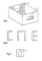
- Fig. 1 shows a purely schematic representation of a bottle crate with through openings 2 formed in the side walls, the cross bar remaining above the through openings 2, which also forms the upper edge of the crate, represents the actual handle 3 of the bottle crate. Furthermore, purely schematically in Fig. 1 on an inner wall of the bottle crate vertically and horizontally extending ribs 1 are shown, which serve to increase the torsional rigidity of the bottle crate.
- Fig. 2 shows conventional profile shapes of handles, whereas Fig. 3 shows a section through a handle 3, from which the shape of the hollow channel 6 is clearly shown. As Fig. 3 shows, the cross-sectional shape of the hollow channel is preferably oval, but depending on the embodiment also circular .
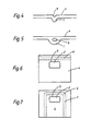
- FIG. 4 shows a conventional rib formation in a side wall 4, wherein a sink mark 5 can be seen quite clearly, which occurs due to the different mass accumulation in the rib area when the shaped bottle crate cools.
- 5 shows a rib design 1, in which a stiffening is achieved by a channel 6 produced by gas injection.
- the hollow channel 6 extends essentially over the entire length of the rib 1.
- FIG. 6 shows a side view of a bottle crate with a handle 3 above a penetration opening 2, a hollow channel 6 produced by gas injection being formed over the entire length of the side wall 4 at the upper edge.
- the hollow channel 6 is shown by dashed lines.
- the hollow channel 6 extends through the handle 3, so that there is a handle design according to FIG. 3.
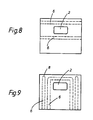
- the gas is blown in from the bottom of the box, the gas flow being U-shaped and thus forming a U-shaped hollow channel 6, which results in a hollow design of the handle 3 and in stiffening of the side wall 4 of the box the hollow U-leg 7 of the hollow channel 6 leads.
- a very tear-resistant handle construction is realized.
- two hollow channels 6 are formed on both sides of the access opening, which leads to a very high torsional rigidity of the bottle crate, in particular in the handle area.
- Such an embodiment is also particularly suitable for bottle crates with comparatively large openings in the side wall, which serve as display surfaces for the bottles accommodated in the crate. It is expedient here to align the hollow channels 6 along the edges of the window-like openings.
- a U-shaped hollow channel 6 is formed.
- the corner areas of the bottle crate are stiffened by vertically extending hollow channels 6, these hollow channels being closed at 8 at the top but being open at the bottom.
- the two lower ends which open into the floor are preferably closed, which also applies to the ends of the hollow channel 6, which is shown in FIGS. 6, 7 and 8.
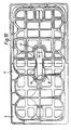
- FIG. 10 shows a bottle crate with a central handle 11, of which only the crossbar 12 serving as a carrying handle is shown in FIG. 10.
- the center handle extends either from the box bottom or from the compartment walls in the form of two opposite support legs 13, which open into the essentially horizontal crossbar 12 and are otherwise integrally formed with this as well as with the rest of the box.
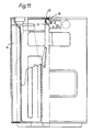
- this center handle 11 is formed over its entire length, i.e. over the length of the two support legs 13 and the length of the crossbar connecting the two support legs, as a closed hollow profile, as can be seen in particular from the section of the crossbar 12 in FIG. 11.
- the hollow profile of the center handle, designated 15, can either be closed or else open.
- the hollow profile is produced by blowing gas into the melt during the formation of the bottle crate, the gas flowing in the plastic core of the molded part to form the center handle without mixing with the material, and a cavity within the center handle as a result of the blown-in gas cushion.
- This cavity 15 is closed at both ends of the center handle 11, i.e. in the region of the junction with the box bottom and in the box walls, either by pulling off the nozzle before the material melt solidifies or the molding box from the nozzle before solidifying the material melt, i.e. is subtracted from the tool as a whole.
- the cavity can also be closed by other suitable measures.
- the hollow channel 15 in certain areas, in particular to form a cavity in the crosspiece 12, this cavity being able to extend to a certain extent into the edge region of the adjacent vertical support strips 13. It is also expedient to form a cavity in the substantial region of the vertical support legs 13, the cavity also advantageously being drawn slightly into the adjoining region of the crosspiece 12.
- gas can be blown in from both sides of the center handle. In a suitable embodiment, the gas was blown in at a pressure in the range of 200 bar.
- hollow profiles can also be provided in the area of the box walls by gas injection, for example in the box corners or in the support profiles designated 14 in the drawings, which extend vertically and one of which is shown in longitudinal section in FIG. 2.
- the invention relates to a bottle crate made of plastic according to the preambles of claims 1 and 2 and methods for producing such bottle crates.
- Bottle crates made of plastic usually consist of two narrow and two long side walls and an open-structured box bottom, with a compartment division, possibly consisting of compartment walls preferably arranged crosswise, being arranged inside the box.
- bottle crates of this type usually have handles which are formed by simple through openings in the bottle crate. Between the upper box edge and the upper edge of the opening, a horizontally extending web is delimited, which serves as a horizontal handle.
- Such horizontal handles are usually produced in the manner of U, C or L cross-sectional profiles. Apart from the fact that these grip profiles are still does not allow comfortable carrying behavior, the breaking stability of such handles leaves something to be desired. Carrying handles can be torn out, particularly if boxes filled with full bottles are handled frequently.
- a plastic bottle crate with four side walls is already known, which has a crate bottom and at least one handle. Although closed stiffening channels are provided in the bottle crate at least in some areas, carrying handles can still be torn out.
- a bottle crate is known from EP-A-0 258 549, which has a central handle for handling the crate.
- the center handle extends in the area of the center of the box from the box bottom or from the compartment walls of the compartments upwards in the form of an upside-down U made of two support legs and a crossbar serving as a handle that connects the support legs
- a bottle crate with double-walled side walls and a double-walled base is known from US-A-3 506 154
- document DE-A 38 23 650 is a republished national document.
- This document discloses a box, one embodiment of which box contains a cavity formed by gas injection during the spraying process. This cavity forms a hollow stiffening channel, which is obviously open at its ends, as is not to be expected otherwise with a gas injection.
- the open design of these stiffening channels in accordance with the above-mentioned document has considerable disadvantages.
- the object of the invention is to produce a bottle crate made of plastic, which is characterized by a very high torsional rigidity.
- This torsional stiffness is to be achieved above all in the area of the handles, in particular in the area of horizontal handles, and an increase in the breaking stability is also to be achieved in order to prevent the handles from tearing out even under heavy loads.
- bottle crates are to be produced which, with good torsional rigidity, have smooth outer surfaces which can be printed well. Finally, the wearing comfort of such bottle crates is to be increased.
- the open profile shape is deviated and, when the bottle case is produced, a cavity is formed within the material of the bottle case by specifically blowing gas under pressure into the still molten material stream to form the bottle case, so that the claim 1 closed hollow stiffening channels are formed at least in the web forming the handle of the bottle crate.
- the stiffening channels are closed to the outside.
- such a stiffening channel or cavity which is enclosed over the circumference by the material of the box wall, makes an extremely torsion-resistant design of a handle that can be realized in a box-shaped and thus as a closed profile, which increases the comfort and also a dirt accumulation largely prevented and, conversely, a good cleaning of the bottle crate allowed.
- the rigidity of the crate can be increased accordingly in a known manner by targeted injection of hollow channels into critical areas of the bottle crate. For example, it is advisable to make the corner profiles of the bottle crates hollow or vertically formed on the side walls make the supporting profiles hollow. Due to this design, rib structures can be avoided, which simplifies the cleaning of the bottle crates. As a result of the omission of the rib structures, largely smooth outer surfaces can be guaranteed, which simplify the cleaning of the bottle crates, simplify the handling of the crates and also increase the wearing comfort in the case of smooth grip surfaces.
- Side walls of the bottle crate can also advantageously be formed with closed hollow chambers, which are achieved by blowing gas into the still molten plastic during the molding process.
- the air can be blown in from the side walls, i.e. from the corner areas, or from the bottom of the box.
- the box can also be injection molded in reverse, which is particularly advantageous for the formation of horizontal handles with closed cavities.
- cavities can be achieved in a targeted manner on bottle crates by simultaneous or time-delayed injection of gas into the melt, the cavities not from the outside are evident.
- the gas is injected into the plastic melt through very narrow nozzles.
- the cavity formation can be influenced in a targeted manner by appropriate arrangement of the nozzles and alignment of the nozzles.
- the nozzles are expediently arranged in such a way that they are more or less stationary with the tool and the finished bottle crate is lifted off the nozzles during removal from the mold.
- the nozzles are arranged to be movable and are introduced for blowing in the gas, so that they extend into the melt flow. At the end of the flow process, the nozzles are withdrawn so that these small injection openings close automatically. In this way, closed hollow channels can be realized in a simple manner at the ends.
- the nozzles are preferably arranged as close as possible to the desired cavity.
- the measures according to the invention can be used to specifically achieve cavities which, according to the invention, contribute to increasing the torsional rigidity and the breaking strength in the area of the carrying handle.
- the handle there is no need to design the handle as U, C or L or other profiles for the purpose of optimizing the strength, which are rather unfavorable in terms of comfort. Rather, a self-contained box profile in a compact design can be realized in the area of the handle, which enables the handle to be gripped comfortably by hand.
- Another advantage of this targeted cavity formation in the handle area is that the cavities can be extended into the remaining wall of the bottle crate, so that the strength continues in the rest of the crate, which results in increased resistance to breakage for the handle Gas for material savings in the manufacture of bottle crates.
- Fig. 1 shows a purely schematic representation of a bottle crate with through openings 2 formed in the set walls, the transverse web remaining above the through openings 2, which also forms the upper edge of the crate, representing the actual handle 3 of the bottle crate. Furthermore, purely schematically in Fig. 1 on an inner wall of the bottle crate vertically and horizontally extending ribs 1 are shown, which serve to increase the torsional rigidity of the bottle crate.
- Fig. 2 shows conventional profile shapes of carrying handles, whereas Fig. 3 shows a section through a carrying handle 3, from which the shape of the hollow channel 6 is clearly shown. As shown in FIG. 3, the cross-sectional shape of the hollow channel is preferably oval, but, depending on the embodiment, also circular.
- Fig. 4 shows a conventional rib formation in a side wall 4, wherein a sink mark 5 can be seen quite clearly, which occurs due to the different mass accumulation in the rib area when the shaped bottle crate cools.
- Fig. 5 shows a rib formation 1, in which a stiffening by a Gas injection generated channel 6 is reached.
- the hollow channel 6 extends essentially over the entire length of the rib 1.
- Flg. 6 shows a side view of a bottle crate with a handle 3 above a passage opening 2, a hollow channel 6 produced by gas injection being formed over the entire length of the side wall 4 at the upper edge.
- the hollow channel 6 is shown by dashed lines.
- the hollow channel 6 extends through the handle 3, so that there is a handle design according to FIG. 3.
- the gas inlet is Solution from the box bottom, the gas flow is U-shaped and thus forms a U-shaped hollow channel 6, which leads to a hollow design of the handle 3 and a stiffening of the box side wall 4 due to the hollow U-legs 7 of the hollow channel 6 clearly a very tear-resistant handle construction is realized.
- FIG. 7 the embodiment according to FIG. 7
- two hollow channels 6 are formed on both sides of the access opening, which leads to a very high torsional rigidity of the bottle crate, in particular in the handle area.
- Such an embodiment is also particularly suitable for bottle crates with comparatively large openings in the side wall, which serve as display areas for the bottles accommodated in the crate. It is expedient here to align the hollow channels 6 along the edges of the window-like openings.
- a U-shaped hollow channel 6 is formed.
- the corner areas of the bottle crate are stiffened by vertically extending hollow channels 6, these hollow channels being closed at 8 at the top but being open at the bottom.
- the two lower ends which open into the floor are preferably closed, which also applies to the ends of the hollow channel 6, which is shown in FIGS. 6, 7 and 8.
- FIG. 10 shows a bottle crate with a central handle 11, of which only the crossbar 12 serving as a carrying handle is shown in FIG. 10.
- the center handle extends either from the box bottom or from the compartment walls in the form of two opposite support legs 13, which open into the essentially horizontal crossbar 12 and are otherwise integrally formed with this as well as with the rest of the box.
- this center handle 11 is formed over its entire length, i.e. over the length of the two support legs 13 and the length of the crossbar connecting the two support legs, as a closed hollow profile, as can be seen in particular from the section of the crossbar 12 in FIG. 11.
- the hollow profile of the center handle, designated 15, can either be closed or else open.
- the hollow profile is produced by blowing gas into the melt during the formation of the bottle crate, the gas flowing in the plastic core of the molded part to form the center handle without mixing with the material, and a cavity within the center handle as a result of the blown-in gas cushion.
- This cavity 15 is closed at both ends of the middle handle 11, i.e. in the region of the junction with the box bottom and in the box walls, either by pulling off the nozzle before the material melt solidifies or the molding box from the nozzle before solidifying the material melt, i.e. is subtracted from the tool as a whole.
- the cavity can also be closed by other suitable measures.
- the hollow channel 15 in certain areas, in particular to form a cavity in the crosspiece 12, this cavity being able to extend to a certain extent into the edge region of the adjacent vertical support strips 13. It is also expedient to form a cavity in the substantial region of the vertical support legs 13, the cavity also advantageously being drawn slightly into the adjoining region of the crosspiece 12.
- gas can be blown in from both sides of the center handle. In a suitable embodiment, the gas was blown in at a pressure in the range of 200 bar.
- hollow profiles can also be provided in the area of the box walls by gas injection, for example in the box corners or in the support profiles designated 14 in the drawings, which extend vertically and one of which is shown in longitudinal section in FIG. 2
Landscapes
- Engineering & Computer Science (AREA)
- Mechanical Engineering (AREA)
- Ceramic Engineering (AREA)
- Manufacturing & Machinery (AREA)
- Details Of Rigid Or Semi-Rigid Containers (AREA)
- Containers Having Bodies Formed In One Piece (AREA)
- Injection Moulding Of Plastics Or The Like (AREA)
- Rigid Containers With Two Or More Constituent Elements (AREA)
Abstract
Claims (7)
Priority Applications (1)
| Application Number | Priority Date | Filing Date | Title |
|---|---|---|---|
| AT89913218T ATE93195T1 (de) | 1988-11-08 | 1989-11-08 | Flaschenkasten aus kunststoff. |
Applications Claiming Priority (5)
| Application Number | Priority Date | Filing Date | Title |
|---|---|---|---|
| DE3837894 | 1988-11-08 | ||
| DE3837894 | 1988-11-08 | ||
| DE3839087A DE3839087C2 (de) | 1988-11-08 | 1988-11-18 | Flaschenkasten aus Kunststoff sowie Verfahren zur Herstellung desselben |
| DE3839087 | 1988-11-18 | ||
| PCT/EP1989/001335 WO1990005676A2 (fr) | 1988-11-08 | 1989-11-08 | Casier a bouteilles en matiere plastique |
Publications (3)
| Publication Number | Publication Date |
|---|---|
| EP0396728A1 EP0396728A1 (fr) | 1990-11-14 |
| EP0396728B1 EP0396728B1 (fr) | 1993-08-18 |
| EP0396728B2 true EP0396728B2 (fr) | 1996-10-16 |
Family
ID=25874038
Family Applications (1)
| Application Number | Title | Priority Date | Filing Date |
|---|---|---|---|
| EP89913218A Expired - Lifetime EP0396728B2 (fr) | 1988-11-08 | 1989-11-08 | Casier a bouteilles en matiere plastique |
Country Status (6)
| Country | Link |
|---|---|
| EP (1) | EP0396728B2 (fr) |
| JP (2) | JP3032872B2 (fr) |
| AU (1) | AU4640489A (fr) |
| BR (1) | BR8907162A (fr) |
| DE (1) | DE8915831U1 (fr) |
| WO (1) | WO1990005676A2 (fr) |
Cited By (2)
| Publication number | Priority date | Publication date | Assignee | Title |
|---|---|---|---|---|
| DE102005023196B4 (de) * | 2005-05-14 | 2008-08-07 | Linpac Materials Handling (Germany) Gmbh | Transportkasten aus Kunststoff, Formen und Verfahren zu seiner Herstellung |
| DE102009030857A1 (de) * | 2009-06-26 | 2011-05-19 | Kabelschlepp Gmbh | Element eines Kettengliedes einer Energieführungskette, das durch ein Fluid-Innendruck-Spritzgieß-Verfahren hergestellt ist |
Families Citing this family (9)
| Publication number | Priority date | Publication date | Assignee | Title |
|---|---|---|---|---|
| DE4035497C2 (de) * | 1990-11-08 | 1994-08-11 | Peguform Werke Gmbh | Vorrichtung zur Herstellung von Transportkästen, insbesondere Flaschenkästen |
| NL9002485A (nl) * | 1990-11-14 | 1992-06-01 | Wavin Bv | Kunststof krat met gedeeltelijk holle handgreep. |
| JPH0510221U (ja) * | 1991-07-16 | 1993-02-09 | アイリスオーヤマ株式会社 | 合成樹脂製容器 |
| CH683332A5 (de) * | 1991-08-13 | 1994-02-28 | Schoeller Plast Ag | Flaschenkasten. |
| JPH0679755A (ja) * | 1992-09-02 | 1994-03-22 | Tenshiyou Denki Kogyo Kk | 合成樹脂成形方法 |
| DE202004018927U1 (de) | 2004-12-07 | 2005-02-24 | Ifco Systems Gmbh | Transportkasten mit klappbaren Seitenteilen aus Kunststoff |
| DE102008006696B4 (de) * | 2008-01-30 | 2015-11-12 | Schoeller Arca Systems Gmbh | Thermo-Behälter mit thermischer Isolierung von Waren für Transport und Lagerung |
| DE102010013704A1 (de) * | 2010-04-01 | 2011-10-06 | Schoeller Arca Systems Gmbh | Behälter aus Kunststoff, insbesondere Flaschenkasten mit einem hohl ausgebildeten Handgriff sowie Verfahren zur Herstellung |
| JP7229515B2 (ja) * | 2018-11-20 | 2023-02-28 | 岐阜プラスチック工業株式会社 | 合成樹脂製ケース |
Family Cites Families (6)
| Publication number | Priority date | Publication date | Assignee | Title |
|---|---|---|---|---|
| US3506154A (en) | 1968-07-08 | 1970-04-14 | Laidlaw Corp | Plastic case for milk bottles |
| FR2223248A1 (en) * | 1973-03-29 | 1974-10-25 | Allibert Exploitation | Plastic crate for stacking in piles - sides are strengthened by hollow pillars to allow stacking at right angles |
| JPS5165551A (en) * | 1974-12-04 | 1976-06-07 | Matsushita Electric Industrial Co Ltd | Denshiteki suitsuchi |
| GB2158002B (en) * | 1984-05-04 | 1987-06-17 | Peerless Foam Moulding Co | Injection moulding |
| EP0258549B2 (fr) * | 1986-09-05 | 1996-05-01 | Schoeller-Plast AG | Casier à bouteilles empilable |
| JPH0788025B2 (ja) * | 1987-04-28 | 1995-09-27 | 三菱瓦斯化学株式会社 | 偏肉補強部構造を有する合成樹脂成形品の製造法 |
-
1989
- 1989-11-08 AU AU46404/89A patent/AU4640489A/en not_active Withdrawn
- 1989-11-08 EP EP89913218A patent/EP0396728B2/fr not_active Expired - Lifetime
- 1989-11-08 JP JP2500159A patent/JP3032872B2/ja not_active Expired - Lifetime
- 1989-11-08 WO PCT/EP1989/001335 patent/WO1990005676A2/fr not_active Ceased
- 1989-11-08 BR BR898907162A patent/BR8907162A/pt not_active IP Right Cessation
- 1989-11-08 DE DE8915831U patent/DE8915831U1/de not_active Expired - Lifetime
-
1998
- 1998-08-27 JP JP24127998A patent/JP3030318B2/ja not_active Expired - Lifetime
Cited By (4)
| Publication number | Priority date | Publication date | Assignee | Title |
|---|---|---|---|---|
| DE102005023196B4 (de) * | 2005-05-14 | 2008-08-07 | Linpac Materials Handling (Germany) Gmbh | Transportkasten aus Kunststoff, Formen und Verfahren zu seiner Herstellung |
| DE102009030857A1 (de) * | 2009-06-26 | 2011-05-19 | Kabelschlepp Gmbh | Element eines Kettengliedes einer Energieführungskette, das durch ein Fluid-Innendruck-Spritzgieß-Verfahren hergestellt ist |
| US8857148B2 (en) | 2009-06-26 | 2014-10-14 | Tsubaki Kabelschlepp GmbH | Element of a chain link of an energy guide chain, produced by means of a fluid internal pressure injection molding process |
| DE102009030857B4 (de) * | 2009-06-26 | 2018-10-31 | Tsubaki Kabelschlepp GmbH | Element eines Kettengliedes einer Energieführungskette, das durch ein Fluid-Innendruck-Spritzgieß-Verfahren hergestellt ist |
Also Published As
| Publication number | Publication date |
|---|---|
| EP0396728B1 (fr) | 1993-08-18 |
| EP0396728A1 (fr) | 1990-11-14 |
| JPH03502192A (ja) | 1991-05-23 |
| WO1990005676A2 (fr) | 1990-05-31 |
| BR8907162A (pt) | 1991-02-26 |
| AU4640489A (en) | 1990-06-12 |
| DE8915831U1 (de) | 1991-09-26 |
| JPH11130038A (ja) | 1999-05-18 |
| WO1990005676A3 (fr) | 1990-06-28 |
| JP3030318B2 (ja) | 2000-04-10 |
| JP3032872B2 (ja) | 2000-04-17 |
Similar Documents
| Publication | Publication Date | Title |
|---|---|---|
| DE60114202T2 (de) | Kunststoffbehälter mit runden schultern | |
| DE1586815C3 (de) | Flaschenträger | |
| EP0396728B2 (fr) | Casier a bouteilles en matiere plastique | |
| DE20313077U1 (de) | Transportkasten aus Kunststoff | |
| CH621742A5 (fr) | ||
| EP1396329B1 (fr) | Procédé et appareil pour produire une section d'un conteneur en forme de boíte | |
| EP0770552B1 (fr) | Casier à bouteilles et procédé de fabrication d'une tel casier | |
| EP0374774B1 (fr) | Casiers à bouteilles avec des éléments horizontaux servant de poignées | |
| US5395010A (en) | Plastic bottle case | |
| EP0572946B1 (fr) | Palette en matière synthétique | |
| DE3839087C2 (de) | Flaschenkasten aus Kunststoff sowie Verfahren zur Herstellung desselben | |
| EP0687630B1 (fr) | Article en matière plastique moulé par injection | |
| EP0738661A1 (fr) | Palette en matière plastique, procèdè et dispositif pour sa fabrication | |
| DE8916070U1 (de) | Flaschenkasten aus Kunststoff | |
| EP0603531B1 (fr) | Casier à bouteilles en matière plastique avec poignée | |
| EP2112076B1 (fr) | Procédé de fabrication d'une caisse de transport fabriquée en une seule pièce en matière plastique | |
| WO1987007577A1 (fr) | Casier a bouteilles gerbable | |
| DE4236781A1 (de) | Transportbehälter, insbesondere Flaschenkasten mit Traggriffen | |
| DE4035497C2 (de) | Vorrichtung zur Herstellung von Transportkästen, insbesondere Flaschenkästen | |
| WO2002020360A2 (fr) | Corps moule par transfert et dispositif et procede pour fabriquer ledit corps | |
| DE4330998A1 (de) | Transportkasten aus Kunststoff | |
| EP2103533B1 (fr) | Caisse de bouteilles en une seule pièce en matière plastique et outil de formage servant à sa fabrication | |
| EP0275919A2 (fr) | Casier en matière plastique, destiné à contenir des récipients, notamment des bouteilles | |
| DE29906586U1 (de) | Kasten | |
| DE7819399U1 (de) | 10er-Minikasten |
Legal Events
| Date | Code | Title | Description |
|---|---|---|---|
| PUAI | Public reference made under article 153(3) epc to a published international application that has entered the european phase |
Free format text: ORIGINAL CODE: 0009012 |
|
| 17P | Request for examination filed |
Effective date: 19900906 |
|
| AK | Designated contracting states |
Kind code of ref document: A1 Designated state(s): AT BE CH DE FR GB IT LI LU NL SE |
|
| 17Q | First examination report despatched |
Effective date: 19920723 |
|
| GRAA | (expected) grant |
Free format text: ORIGINAL CODE: 0009210 |
|
| AK | Designated contracting states |
Kind code of ref document: B1 Designated state(s): AT BE CH DE FR GB IT LI LU NL SE |
|
| REF | Corresponds to: |
Ref document number: 93195 Country of ref document: AT Date of ref document: 19930915 Kind code of ref document: T |
|
| GBT | Gb: translation of ep patent filed (gb section 77(6)(a)/1977) |
Effective date: 19930817 |
|
| REF | Corresponds to: |
Ref document number: 58905327 Country of ref document: DE Date of ref document: 19930923 |
|
| ET | Fr: translation filed | ||
| PLBI | Opposition filed |
Free format text: ORIGINAL CODE: 0009260 |
|
| ITF | It: translation for a ep patent filed | ||
| 26 | Opposition filed |
Opponent name: OBERLAND PLASTIC GMBH Effective date: 19930924 |
|
| EPTA | Lu: last paid annual fee | ||
| NLR1 | Nl: opposition has been filed with the epo |
Opponent name: OBERLAND PLASTIC GMBH. |
|
| EAL | Se: european patent in force in sweden |
Ref document number: 89913218.7 |
|
| PGFP | Annual fee paid to national office [announced via postgrant information from national office to epo] |
Ref country code: LU Payment date: 19960101 Year of fee payment: 7 |
|
| PLAW | Interlocutory decision in opposition |
Free format text: ORIGINAL CODE: EPIDOS IDOP |
|
| PLAW | Interlocutory decision in opposition |
Free format text: ORIGINAL CODE: EPIDOS IDOP |
|
| PUAH | Patent maintained in amended form |
Free format text: ORIGINAL CODE: 0009272 |
|
| STAA | Information on the status of an ep patent application or granted ep patent |
Free format text: STATUS: PATENT MAINTAINED AS AMENDED |
|
| 27A | Patent maintained in amended form |
Effective date: 19961016 |
|
| AK | Designated contracting states |
Kind code of ref document: B2 Designated state(s): AT BE CH DE FR GB IT LI LU NL SE |
|
| REG | Reference to a national code |
Ref country code: CH Ref legal event code: AEN Free format text: AUFRECHTERHALTUNG DES PATENTES IN GEAENDERTER FORM |
|
| PG25 | Lapsed in a contracting state [announced via postgrant information from national office to epo] |
Ref country code: LU Free format text: LAPSE BECAUSE OF NON-PAYMENT OF DUE FEES Effective date: 19961108 |
|
| NLR2 | Nl: decision of opposition | ||
| EN | Fr: translation not filed | ||
| EN | Fr: translation not filed |
Free format text: CORRECTIONS |
|
| EN | Fr: translation not filed |
Free format text: BO 97/11 PAGES 225, LA MENTION DE LA DELIVRANCE APRES OPPOSITION AINSI QUE LA MENTION DE LA NON REMISE DE CETE TRADUCTION APRES OPPOSITION |
|
| REG | Reference to a national code |
Ref country code: GB Ref legal event code: IF02 |
|
| PGFP | Annual fee paid to national office [announced via postgrant information from national office to epo] |
Ref country code: GB Payment date: 20061123 Year of fee payment: 18 Ref country code: SE Payment date: 20061123 Year of fee payment: 18 |
|
| PGFP | Annual fee paid to national office [announced via postgrant information from national office to epo] |
Ref country code: IT Payment date: 20061130 Year of fee payment: 18 |
|
| EUG | Se: european patent has lapsed | ||
| GBPC | Gb: european patent ceased through non-payment of renewal fee |
Effective date: 20071108 |
|
| PG25 | Lapsed in a contracting state [announced via postgrant information from national office to epo] |
Ref country code: SE Free format text: LAPSE BECAUSE OF NON-PAYMENT OF DUE FEES Effective date: 20071109 |
|
| PG25 | Lapsed in a contracting state [announced via postgrant information from national office to epo] |
Ref country code: GB Free format text: LAPSE BECAUSE OF NON-PAYMENT OF DUE FEES Effective date: 20071108 |
|
| PGFP | Annual fee paid to national office [announced via postgrant information from national office to epo] |
Ref country code: NL Payment date: 20081120 Year of fee payment: 20 Ref country code: CH Payment date: 20081124 Year of fee payment: 20 |
|
| PGFP | Annual fee paid to national office [announced via postgrant information from national office to epo] |
Ref country code: AT Payment date: 20081120 Year of fee payment: 20 |
|
| PGFP | Annual fee paid to national office [announced via postgrant information from national office to epo] |
Ref country code: BE Payment date: 20081203 Year of fee payment: 20 |
|
| PGFP | Annual fee paid to national office [announced via postgrant information from national office to epo] |
Ref country code: FR Payment date: 20081118 Year of fee payment: 20 |
|
| PGFP | Annual fee paid to national office [announced via postgrant information from national office to epo] |
Ref country code: DE Payment date: 20090126 Year of fee payment: 20 |
|
| PG25 | Lapsed in a contracting state [announced via postgrant information from national office to epo] |
Ref country code: IT Free format text: LAPSE BECAUSE OF NON-PAYMENT OF DUE FEES Effective date: 20071108 |
|
| REG | Reference to a national code |
Ref country code: CH Ref legal event code: PL |
|
| BE20 | Be: patent expired |
Owner name: *SCHOELLER INTERNATIONAL ENGINEERING K.G. Effective date: 20091108 |
|
| NLV7 | Nl: ceased due to reaching the maximum lifetime of a patent |
Effective date: 20091108 |
|
| PG25 | Lapsed in a contracting state [announced via postgrant information from national office to epo] |
Ref country code: NL Free format text: LAPSE BECAUSE OF EXPIRATION OF PROTECTION Effective date: 20091108 |