EP0687845B1 - Système enfilable d'angle pour raccords de tuyaux à brides - Google Patents
Système enfilable d'angle pour raccords de tuyaux à brides Download PDFInfo
- Publication number
- EP0687845B1 EP0687845B1 EP95109124A EP95109124A EP0687845B1 EP 0687845 B1 EP0687845 B1 EP 0687845B1 EP 95109124 A EP95109124 A EP 95109124A EP 95109124 A EP95109124 A EP 95109124A EP 0687845 B1 EP0687845 B1 EP 0687845B1
- Authority
- EP
- European Patent Office
- Prior art keywords
- flange
- wall
- duct
- frame
- pieces
- Prior art date
- Legal status (The legal status is an assumption and is not a legal conclusion. Google has not performed a legal analysis and makes no representation as to the accuracy of the status listed.)
- Expired - Lifetime
Links
Images


Classifications
-
- F—MECHANICAL ENGINEERING; LIGHTING; HEATING; WEAPONS; BLASTING
- F24—HEATING; RANGES; VENTILATING
- F24F—AIR-CONDITIONING; AIR-HUMIDIFICATION; VENTILATION; USE OF AIR CURRENTS FOR SCREENING
- F24F13/00—Details common to, or for air-conditioning, air-humidification, ventilation or use of air currents for screening
- F24F13/02—Ducting arrangements
- F24F13/0209—Ducting arrangements characterised by their connecting means, e.g. flanges
-
- F—MECHANICAL ENGINEERING; LIGHTING; HEATING; WEAPONS; BLASTING
- F16—ENGINEERING ELEMENTS AND UNITS; GENERAL MEASURES FOR PRODUCING AND MAINTAINING EFFECTIVE FUNCTIONING OF MACHINES OR INSTALLATIONS; THERMAL INSULATION IN GENERAL
- F16L—PIPES; JOINTS OR FITTINGS FOR PIPES; SUPPORTS FOR PIPES, CABLES OR PROTECTIVE TUBING; MEANS FOR THERMAL INSULATION IN GENERAL
- F16L23/00—Flanged joints
- F16L23/12—Flanged joints specially adapted for particular pipes
- F16L23/14—Flanged joints specially adapted for particular pipes for rectangular pipes
-
- Y—GENERAL TAGGING OF NEW TECHNOLOGICAL DEVELOPMENTS; GENERAL TAGGING OF CROSS-SECTIONAL TECHNOLOGIES SPANNING OVER SEVERAL SECTIONS OF THE IPC; TECHNICAL SUBJECTS COVERED BY FORMER USPC CROSS-REFERENCE ART COLLECTIONS [XRACs] AND DIGESTS
- Y10—TECHNICAL SUBJECTS COVERED BY FORMER USPC
- Y10S—TECHNICAL SUBJECTS COVERED BY FORMER USPC CROSS-REFERENCE ART COLLECTIONS [XRACs] AND DIGESTS
- Y10S138/00—Pipes and tubular conduits
- Y10S138/04—Air conditioning
Definitions
- This invention relates generally to duct systems used in the heating, ventilating and/or air conditioning fields.
- the ducts typically are rectangular in cross section and are formed in sections that must be joined together to complete the system. More particularly, the invention relates to flange frames used in connecting adjacent duct sections together.
- Duct joining systems are well known and are widely utilized to join together the ends of adjacent duct sections. When the sections are properly connected, the ducts are used to convey conditioned air from a central system to remote locations so as to provide heating, cooling and ventilation to these locations.
- the prior art teaches numerous, different flange systems for connecting the rectangular duct sections.
- One such system utilizes what are termed "slip-on" flanges which are roll formed metal pieces usually made in 10 or 20 foot random lengths that are cut-to-length in the shop or on the job site to fit the duct sections. These flange pieces are made in a variety of cross sectional configurations so as to accommodate gaskets, sealants and different mechanical fasteners.
- the installers of the ducts use the roll formed metal flange pieces that have been produced in random lengths and cut them to the proper length. Then with the use of separate corner pieces, such as those shown in Arnoldt, U.S. Patent No. 4,218,079, the flange and corner pieces are assembled into a frame which is then attached to the ends of the rectangular duct sections. The duct sections are then connected using suitable mechanical fasteners joining the frames.
- each duct section requires four corners and four flange pieces to make a frame, and thus each duct connection requires eight corners and eight flange pieces. Because the average duct system in a commercial installation requires hundreds and sometimes thousands of joint connections, the cost of these connections using corner pieces adds to a considerable expense.
- the labor required to make up the flange frames by cutting the random lengths of roll-formed metal flange pieces to the proper length to make the flange frames adds to the installation costs as does scrap loss from the random lengths. There is also a certain amount of danger in cutting the random lengths of roll-formed flange pieces to length in the shop or on-the-job site to form the frames. Considerable savings in both labor and material can be achieved if improved flange system did not require the use of corner pieces.
- US-A-4461499 relates to a system for adjoining abutting ends of duct sections which requires formation of four flanges at the end of a duct section and protruding locking tabs on each flange.
- Four U- or V-shaped coupling members having means to engage the locking tabs are provided to secure adjacent flanges on two duct sections.
- the coupling members extend past the duct sections at each side to overlap an adjacent coupling member, the overlapped coupling members being secured by a bolt.
- US-A-4461499 does not relate to a slip-on flange system and for this reason the system is relatively complex from a manufacturing and installation standpoint.
- the present invention provides a cornerless slip-on flange system for connecting the ends of rectangular duct sections having four walls each of which terminates in a straight, flat end to form the duct section, said flange system comprising a plurality of flange pieces which are connectable to form a rectangular frame to be fitted on the ends of the walls of one of the duct sections to be connected, each flange piece having a duct wall for connection with the end of the wall of a duct section and a frame wall extending at substantially a right angle to the duct wall, the duct wall of each flange piece having an inner portion and an outer portion spaced from the inner portion to form a space for receiving the straight end of a wall of a duct section that is to be connected, the frame wall being connectable with the frame wall of another duct section to join the sections, the frame being fitted on the ends of the walls of a duct section by slipping the end walls of a duct section into the respective spaces in the duct walls of the flange pieces, the frame consisting
- flange pieces are preformed to the proper length each with a male end and a female end that are notched and cut as a part of the forming operation.
- the flanges are identical, except for possibly the length which is determined according to the size of the rectangular duct sections that are to be joined.
- These preformed flange pieces are then provided to the installer who can assemble the flange frames and install them on the ends of the ducts.
- the male and female ends of the flange pieces are joined to form the corners, and the flange pieces are preformed with openings to receive standard fasteners so that the duct sections can now be joined together in the customary manner.
- duct sections each having parallel spaced-apart side walls 10 joined to a top wall 12 and a bottom wall 14.
- the side walls 10, top wall 12 and bottom wall 14 are constructed of sheet material to form an enclosed duct for conveying conditioned air, as is well known to those skilled in the art.
- a series of duct sections must be joined together and the joints sealed by the contractor or installer.
- flange pieces each indicated generally by the reference numeral 16, are assembled to form a rectangular frame in the manner described hereinafter.
- the frames are assembled, they are slipped over the edges of the side walls 10, top wall 12 and bottom wall 14 of the duct sections which are then connected together by the insertion of suitable fasteners (not shown) that interconnect the flange pieces 16 of one duct section to the flange pieces 16 of the other duct section.
- suitable fasteners not shown
- a suitable gasket 18 or other sealant is positioned between the flange pieces 16 of duct sections to be joined so that when the duct sections are connected, an air tight seal will be formed.
- Fig. 2 is a cross-sectional view illustrating the cross-sectional shape of the flange pieces 16.
- a particular configuration of flange pieces 16 has been illustrated, it will be understood that a variety of cross-sectional shapes are known and can be used in applying the principles of the invention.
- a relatively simple and common cross-sectional shape is illustrated in Fig. 2 for each of the flange pieces 16.
- each of the flange pieces 16 includes a duct wall 19 having an inner portion 20 and an outer portion 22 spaced slightly apart with the free edge 24 of the outer portion 22 bent outwardly to facilitate reception between the portions 20 and 22 of a duct side wall 10, top wall 12 or bottom wall 14 as the case may be.
- the inner portion 20 of duct wall 19 is joined to an outwardly extending inner leg 26 which is joined to an outer leg 28 by edge 30 to form the frame wall 31.
- the inner leg 26 has an "S" shaped portion 32 formed along its entire length that provides a recess 34 that receives and locks the edge of the side wall 10, for example, into the duct wall 19.
- the inner leg 26, outer leg 28, edge 30 and inner portion 20 and outer portion 22 are all continuously formed in a well-known manner by a roll-forming operation to produce the desired configuration of a flange piece 16 as illustrated in the drawings.
- the flange pieces 16 that are described in the preferred embodiment disclosed herein are commonly known in the industry as "slip-on" flanges, and are used in connecting duct sections by slipping the flanges, when assembled into a frame, onto the edges of the walls of the duct sections.
- slip-on flanges L-shaped corner pieces must be used to join the flange pieces, these corner pieces being inserted into the space 36 (see Fig. 2) of adjoining flange pieces. The corner pieces are then connected by suitable fasteners to join the duct sections.
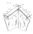
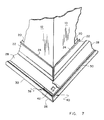
- each flange piece 16 has a male end 38 and a female end 40.
- the male end 38 of a flange piece 16 is an extension of the inner leg 26 and outer leg 28 of the frame wall 31 beyond the inner portion 20 and outer portion 22 of the duct wall 19.
- the male end 38 has a slot 41 formed through both the inner leg 26 and the outer leg 28 along the edge 30. This slot 41 allows the outer edges of the inner leg 26 and outer leg 28 of the female end 40 to fit tightly against the inside of the edge 30 of the male end 38 so as to close the corner without a gap.
- the female end 40 is formed by extending the inner leg 26 and outer leg 28 of the frame wall 31 beyond the inner portion 20 and outer portion 22 of the duct wall 19.
- the inner leg 26 and outer leg 28 of the male end 38 are positioned inside the inner leg 26 and outer leg 28 of the female end 40 with the edges of the legs 26 and 28 abutting the inside of the edge 30 of the female end 40.
- the male end 28 is provided with an opening 42 that extends through both the inner leg 26 and outer leg 28, and similarly the female end 40 has an opening 44 that extends through both the inner leg 26 and outer leg 28. Openings 42 and 44 are positioned so that when the male end 38 and female end 40 of adjoining flanges 16 are joined, the openings 42 and 44 will be in alignment. Since the flange pieces 16 are identical, when they are assembled into a frame and installed on the side walls 10, top wall 12 and bottom wall 14 by slipping the duct walls 19 over the edges of the duct, the male end 38 of one flange piece 16 (e.g. on a side wall 10) will be positioned inside the female end 40 of an adjacent flange piece 16 on the top wall 12, for example.
- the openings 42 of the male end 38 of one flange piece 16 will be in alignment with the opening 44 of the female end 40 of the adjacent flange piece 16. These openings are for receiving standard suitable fasteners such as bolts (not shown) that will hold two duct sections tightly together.
- the flange pieces 16 forming the frame of one duct section can be joined to the flange pieces 16 forming the frame of another duct section of any suitable manner, such as by welding the frames together.
- Flange pieces of the invention can be produced on a production roll-forming extruding line and are ready for assembly to the duct sections as manufactured. Once produced for a duct system of a particular size, the flange pieces require no further cutting prior to assembly and installation on the duct ends, thus eliminating scrap as well as the labor for cutting the pieces.
- Use of the slip-on flange system of the invention further reduces the possibility of injury since it eliminates the cutting operation in the shop or on the job-site and also reduces annoying noise that occurs during the cutting.
Landscapes
- Engineering & Computer Science (AREA)
- General Engineering & Computer Science (AREA)
- Mechanical Engineering (AREA)
- Chemical & Material Sciences (AREA)
- Combustion & Propulsion (AREA)
- Duct Arrangements (AREA)
- Flanged Joints, Insulating Joints, And Other Joints (AREA)
Claims (3)
- Système à bride à glisser sans coin destiné au raccordement des extrémités de tronçons d'un conduit rectangulaire ayant quatre parois (10, 12, 14) se terminant chacune par une extrémité plate et rectiligne pour la formation du tronçon de conduit, le système à bride comprenant plusieurs pièces (16) de bride qui peuvent être raccordées pour la formation d'un cadre rectangulaire destiné à être monté aux extrémités des parois de l'un des tronçons de conduit à raccorder, chaque pièce (16) de bride ayant une paroi (19) de conduit destinée à être raccordée à l'extrémité de la paroi d'un tronçon de conduit et une paroi (26) de cadre dépassant en direction pratiquement perpendiculaire à la paroi de conduit, la paroi de conduit de chaque pièce de bride ayant une partie interne (20) et une partie externe (22) placée à distance de la partie interné pour la formation d'un espace de logement de l'extrémité rectiligne d'une paroi (10, 12, 14) d'un tronçon de conduit qui doit être raccordé, la paroi de cadre pouvant être raccordée à la paroi de cadre d'un autre tronçon de conduit pour le raccordement des tronçons, le cadre étant monté sur les extrémités de la paroi d'un tronçon de conduit par glissement des parois d'extrémité d'un tronçon du conduit dans les espaces respectifs des parois de conduit (20, 22) des pièces (16) de bride, le cadre comprenant quatre pièces (16) de bride, la paroi (26) de cadre de chaque pièce (16) de bride ayant une extrémité mâle (38) et une extrémité femelle (40), l'extrémité mâle (38) d'une première pièce (16) de bride pouvant être raccordée directement à l'extxémité femelle (40) d'une autre pièce (16) de bride lorsque les pièces de bride sont placées perpendiculairement l'une à l'autre pour la formation d'un cadre sans pièce de coin, le cadre, aux extrémités des parois d'un premier tronçon de conduit, étant destiné à être raccordé au cadre placé sur les extrémités des parois d'un autre tronçon de conduit.
- Système à bride à glisser sans coin selon la revendication 1, caractérisé en ce que la paroi (26) de cadre de chaque pièce de bride possède une paroi interne (28) et une paroi externe (26) distante de la paroi interne, la paroi de cadre, à la fois à l'extrémité mâle et à l'extrémité femelle, s'étendant au-delà de la paroi (19) de conduit, la paroi interne (28) et la paroi externe (26) de l'extrémité mâle (38) d'une première pièce (16) de bride pouvant être insérées entre la paroi interne (28) et la paroi externe (26) de l'extxémité femelle (40) d'une autre pièce (16) de bride pour la formation d'un coin d'un cadre lorsque deux pièces de bride sont raccordées.
- Système à bride à glisser sans coin selon la revendication 2, caractérisé en oe qu'une ouverture (42, 44) est formée dans l'extrémité mâle (38) et dans l'extrémité femelle (40) de chaque pièce (16) de bride et traverse ces extrémités, les ouvertures (42, 44) étant disposées afin que l'ouverture (42) de l'extrémité mâle (38) d'une première pièce (16) de bride soient alignées sur l'ouverture (44) de l'extrémité femelle (40) d'une autre pièce (16) de bride lorsqu'elles sont raccordées pour la formation d'un cadre, les ouvertures alignées (42, 44) étant destinées à loger des dispositifs de fixation destinés à raccorder les cadres des deux tronçons de conduit.
Applications Claiming Priority (2)
| Application Number | Priority Date | Filing Date | Title |
|---|---|---|---|
| US08/260,477 US5450879A (en) | 1994-06-14 | 1994-06-14 | Cornerless slip-on flange system for duct connections |
| US260477 | 2002-09-30 |
Publications (2)
| Publication Number | Publication Date |
|---|---|
| EP0687845A1 EP0687845A1 (fr) | 1995-12-20 |
| EP0687845B1 true EP0687845B1 (fr) | 1998-12-23 |
Family
ID=22989331
Family Applications (1)
| Application Number | Title | Priority Date | Filing Date |
|---|---|---|---|
| EP95109124A Expired - Lifetime EP0687845B1 (fr) | 1994-06-14 | 1995-06-13 | Système enfilable d'angle pour raccords de tuyaux à brides |
Country Status (4)
| Country | Link |
|---|---|
| US (1) | US5450879A (fr) |
| EP (1) | EP0687845B1 (fr) |
| JP (1) | JPH08110080A (fr) |
| DE (1) | DE69506788T2 (fr) |
Families Citing this family (34)
| Publication number | Priority date | Publication date | Assignee | Title |
|---|---|---|---|---|
| US6298555B1 (en) * | 1995-09-20 | 2001-10-09 | Al International Srl | Method of making a duct utilizing a grip flange |
| US5865478A (en) * | 1997-05-22 | 1999-02-02 | Lin; Hung Da | Coupling device for duct |
| US6105227A (en) * | 1998-01-19 | 2000-08-22 | Bota; Victor | Apparatus and methods for manufacturing ducts |
| US6378184B1 (en) | 1998-01-19 | 2002-04-30 | Cleveland Tool & Machine | Apparatus and method for manufacturing ducts |
| DE29801851U1 (de) * | 1998-02-04 | 1998-05-07 | Buser, Hermann, 67659 Kaiserslautern | Rahmen aus Blech-Hohlprofilen zum Anbringen an den Enden von Blechkanälen |
| US7885899B1 (en) * | 2000-02-08 | 2011-02-08 | Ipass Inc. | System and method for secure network purchasing |
| US6363764B1 (en) | 2000-02-22 | 2002-04-02 | Cleveland Tool & Machine | Forming apparatus for duct members |
| US6497256B1 (en) * | 2001-07-13 | 2002-12-24 | Carrier Corporation | Thermal barrier for air handling unit (AHU) cabinet |
| US9101969B2 (en) | 2002-02-01 | 2015-08-11 | Jeffrey Allen Hermanson | Rectangular/square spiral ducting systems with flange connectors |
| EP1579140A4 (fr) * | 2002-09-23 | 2009-09-09 | Met Coil Systems Corp | Element de jonction a pose rapide pour conduite |
| EP1562716A4 (fr) * | 2002-09-23 | 2008-03-12 | Met Coil Systems Corp | Appareil de fermeture par soudure |
| ES2247880B1 (es) * | 2003-08-04 | 2007-05-01 | Talleres Bensa, S.L. | Conducto de ventilacion con junta de union incorporada. |
| US7195290B2 (en) * | 2003-11-13 | 2007-03-27 | William Christopher Duffy | Apparatus for a fire-rated duct |
| US7234734B2 (en) * | 2005-01-31 | 2007-06-26 | Met-Coil Systems, Llc | Integral transverse flanges for a duct connecting system |
| GB0503535D0 (en) * | 2005-02-19 | 2005-03-30 | Connecting insulated duct | |
| US20080056817A1 (en) * | 2006-08-30 | 2008-03-06 | Salvatore Fasanella | Corner connector for rectangular duct work |
| US7681930B2 (en) * | 2006-11-10 | 2010-03-23 | Formtek, Inc. | Duct flange |
| WO2008073837A2 (fr) * | 2006-12-08 | 2008-06-19 | Jeffrey Allen Hermanson | Systèmes de conduit en spirale rectangulaire/carré avec connecteurs à brides |
| US9212770B2 (en) * | 2007-07-18 | 2015-12-15 | RAM Developing, LLC | Method and apparatus for attaching flange portions to ducts |
| FR2944212B1 (fr) * | 2009-04-09 | 2012-03-23 | Vraco Sas | Clapet coupe-feu |
| US10539337B2 (en) | 2009-11-24 | 2020-01-21 | Jeffrey Allen Hermanson | Sealed and/or reinforced flanged ring connector for single- and double-wall HVAC ducting |
| CA2781617C (fr) | 2009-11-24 | 2018-06-19 | Jeffrey Allen Hermanson | Connecteurs a joint debout pour gaine |
| EP2567156B1 (fr) * | 2010-08-17 | 2013-09-25 | Walsh Intellectual Property Ltd. | Procédé de fabrication d'un élément de conduite |
| CN102155780B (zh) * | 2011-04-26 | 2013-02-27 | 梁浩鉴 | 一种风口 |
| FR2974880B1 (fr) * | 2011-05-04 | 2013-07-12 | F 2A Fabrication Aeraulique Et Acoustique | Barrette pour encadrement de manchette |
| US9074788B2 (en) | 2012-01-06 | 2015-07-07 | William Christopher Duffy | Fire-rated modular duct assembly suitable for exhausting flammable or hazardous gases, vapours and other materials |
| US9377339B2 (en) * | 2012-09-19 | 2016-06-28 | Pius O. Ileogben | Frame support for a hood vent measurement device |
| US10024569B2 (en) | 2013-10-10 | 2018-07-17 | William Christopher Duffy | Fire-rated modular duct assembly and improvements therein |
| US9371941B1 (en) | 2013-11-06 | 2016-06-21 | Ptm Manufacturing, Llc | Exterior ductwork system |
| CA2933338C (fr) | 2013-12-12 | 2022-07-05 | Capital Hardware Supply, Inc. | Dispositif de joint d'etancheite de coin pour reseau de gaines pour air climatise et procede d'assemblage d'un tel reseau de gaines pour empecher des fuites d'air |
| US20160327306A1 (en) * | 2015-05-04 | 2016-11-10 | James MUTZENEEK | Flange corner clip |
| US10976070B1 (en) | 2017-03-31 | 2021-04-13 | Albers Mechanical Contractors, Inc. | Foam core duct system protected by metal sleeves with integral flanges |
| WO2018231218A1 (fr) | 2017-06-14 | 2018-12-20 | Cleveland Tool & Machine, Inc. | Appareil et procédé de production d'éléments de conduit |
| US11333390B2 (en) * | 2020-03-25 | 2022-05-17 | Durasystems Barriers Inc. | Fire-rated ventilation duct and improvements therein |
Family Cites Families (40)
| Publication number | Priority date | Publication date | Assignee | Title |
|---|---|---|---|---|
| US6428A (en) * | 1849-05-08 | Lug and link eor connecting pipes | ||
| US565499A (en) * | 1896-08-11 | Richard pattison | ||
| US634275A (en) * | 1899-03-16 | 1899-10-03 | Edward V Schenck | Box-flange coupling for sheet-metal pipes. |
| US641580A (en) * | 1899-04-24 | 1900-01-16 | Michael Cummins | Flue or pipe coupling. |
| US726004A (en) * | 1902-12-06 | 1903-04-21 | Emil Gustav Herman Stein | Coupling for air-conduits. |
| US760216A (en) * | 1903-12-23 | 1904-05-17 | Harry H Laws | Flue or duct. |
| US913685A (en) * | 1908-12-15 | 1909-03-02 | David C Boyd | Culvert. |
| US2275572A (en) * | 1939-05-02 | 1942-03-10 | William S Somers | Prefabricated conduit |
| US2330769A (en) * | 1941-09-03 | 1943-09-28 | Henry E Wichner | Duct for air conditioning systems |
| US2396030A (en) * | 1943-01-08 | 1946-03-05 | Augustus P Terry | Fastener for paper forms and the like |
| US2498753A (en) * | 1947-03-22 | 1950-02-28 | Deitsch Frank | Duct or the like |
| US2709454A (en) * | 1950-09-08 | 1955-05-31 | Thomas C Coulters | Heating and ventilating duct |
| NO116612B (fr) * | 1965-05-05 | 1969-04-21 | United Shoe Machinery Ab | |
| US3415543A (en) * | 1965-07-08 | 1968-12-10 | Henry M. Keating | Coupling frame |
| US3347569A (en) * | 1965-10-04 | 1967-10-17 | Wallace I Lindgren | Conduit connecting structure and method |
| US3712649A (en) * | 1965-10-11 | 1973-01-23 | D Martin | Apparatus for supporting and retaining low density webs |
| AT306982B (de) * | 1969-12-09 | 1973-05-10 | Mez Georg | Vorgefertigter Anschlußflansch für Kanalabschnitte von rechteckigen Klimatisierungskanälen |
| US3754782A (en) * | 1971-06-18 | 1973-08-28 | Cleats Mfg Inc | Corner device for duct joints |
| FR2257058B1 (fr) * | 1974-01-04 | 1983-04-01 | Mez Georg | |
| US3934905A (en) * | 1974-01-07 | 1976-01-27 | Johns-Manville Corporation | Expansion joint |
| CH594161A5 (en) * | 1975-11-27 | 1977-12-30 | Schmidlin Ag | Connector for ducts of air conditioning plant - has channel cross section with folded slot for clamping duct ends |
| US4123094A (en) * | 1975-12-13 | 1978-10-31 | Gunter Smitka | Duct joint assembly |
| DE7721055U1 (de) * | 1977-07-05 | 1979-02-15 | Smitka, Guenter, 5860 Iserlohn | Blecherner KanalschuB mit Flanschverbindung |
| CH632328A5 (de) * | 1977-11-09 | 1982-09-30 | Guenter Smitka | Flanschverbindung. |
| US4218079A (en) * | 1978-01-26 | 1980-08-19 | Ductmate Industries, Inc. | Flange type duct joint assembly |
| CA1106419A (fr) * | 1978-01-26 | 1981-08-04 | Peter J. Arnoldt | Joint a brides avec garniture d'etancheite pour gaines |
| US4662661B1 (en) * | 1978-01-26 | 1997-05-13 | Ductmate Ind Inc | Flange type duct joint assembly and seal arrangement therefor |
| GB2082282B (en) * | 1978-08-14 | 1983-04-07 | Ductmate Ind Inc | Improvements in or relating to flange type duct joints |
| US4584756A (en) * | 1978-08-14 | 1986-04-29 | Ductmate Industries, Inc. | Flange type duct joint assembly and seal arrangement therefor |
| CA1132627A (fr) * | 1978-10-19 | 1982-09-28 | Michael T. Sullivan | Systeme d'accouplement de conduite |
| US4283080A (en) * | 1980-01-02 | 1981-08-11 | Kenji Nakajima | Flange for a duct |
| US4461499A (en) * | 1983-03-23 | 1984-07-24 | Industrial Air, Inc. | Transverse joint system for sheet metal ducts |
| DE3340503C1 (de) * | 1983-11-09 | 1985-02-07 | Karl Meinig KG, 7201 Rietheim-Weilheim | Zweiteiliges Eckwinkelstueck fuer Verbindungsflansche von Blechkanalabschnitten |
| US4542923A (en) * | 1983-12-07 | 1985-09-24 | Crosse Frank X | Duct jointing system |
| US4564227A (en) * | 1984-01-26 | 1986-01-14 | Murck James W | Flanged duct joint utilizing snap-in corner pieces |
| DE3515737A1 (de) * | 1985-05-02 | 1986-11-06 | Karl Meinig KG, 7201 Rietheim-Weilheim | Flanschring fuer rohre |
| US4995648A (en) * | 1989-08-29 | 1991-02-26 | Bullock Mfg. Pty. Ltd | Locking flange clip |
| US5356184A (en) * | 1992-01-10 | 1994-10-18 | Industrial Air, Inc. | Corner pieces for improved duct connector |
| US5253901A (en) * | 1992-01-10 | 1993-10-19 | Industrial Air, Inc. | Duct reinforcement |
| GB2269868B (en) * | 1992-08-17 | 1995-08-02 | Arnhold & Co Limited | A duct assembly and a seal therefor |
-
1994
- 1994-06-14 US US08/260,477 patent/US5450879A/en not_active Expired - Lifetime
-
1995
- 1995-06-13 EP EP95109124A patent/EP0687845B1/fr not_active Expired - Lifetime
- 1995-06-13 DE DE69506788T patent/DE69506788T2/de not_active Expired - Fee Related
- 1995-06-14 JP JP7147292A patent/JPH08110080A/ja active Pending
Also Published As
| Publication number | Publication date |
|---|---|
| DE69506788D1 (de) | 1999-02-04 |
| US5450879A (en) | 1995-09-19 |
| JPH08110080A (ja) | 1996-04-30 |
| EP0687845A1 (fr) | 1995-12-20 |
| DE69506788T2 (de) | 1999-09-02 |
Similar Documents
| Publication | Publication Date | Title |
|---|---|---|
| EP0687845B1 (fr) | Système enfilable d'angle pour raccords de tuyaux à brides | |
| CA1132627A (fr) | Systeme d'accouplement de conduite | |
| US2963783A (en) | Sheet metal fittings | |
| US3630549A (en) | Frame and cleat joint connector for ducts | |
| US10557570B2 (en) | Method and apparatus for suspending duct by inserted corner members | |
| US5165730A (en) | Duct joining system | |
| US6758502B2 (en) | Coupling ring for ventilation ducts, and method of connecting ventilation ducts | |
| US4537430A (en) | Duct joining system | |
| US2752950A (en) | Connection means for heating and ventilating ducts | |
| JPH03117707A (ja) | フランジ締結クリップ | |
| US20090058078A1 (en) | Sealed ductwork | |
| US5195789A (en) | Slip lock connector assembly for joining sheet metal ducts | |
| US10066763B2 (en) | Method and apparatus for suspending duct by inserted corner members | |
| CA1239884A (fr) | Raccords a bride pour conduits | |
| US20090309358A1 (en) | Air flow ducts | |
| US20030006611A1 (en) | Fabricated oval duct connector | |
| US7744134B2 (en) | Connecting insulated duct | |
| AU2017203186B2 (en) | Method and apparatus for suspending duct by inserted corner members | |
| US2709454A (en) | Heating and ventilating duct | |
| US3917323A (en) | Connecting apparatus for an air duct system | |
| RU2060428C1 (ru) | Стыковое соединение между двумя плоскоовальными трубчатыми секциями из листового металла | |
| EP1022520B1 (fr) | Système pour l'accouplement des sections des conduites dans les systèmes de conditionnement d'air | |
| KR940005037Y1 (ko) | 공기 조화기용 판넬 | |
| AU2013257398B2 (en) | Method and apparatus for suspending duct by inserted corner members | |
| CA1168276A (fr) | Systeme d'accouplement de sections de conduite |
Legal Events
| Date | Code | Title | Description |
|---|---|---|---|
| PUAI | Public reference made under article 153(3) epc to a published international application that has entered the european phase |
Free format text: ORIGINAL CODE: 0009012 |
|
| AK | Designated contracting states |
Kind code of ref document: A1 Designated state(s): BE DE FR GB IT |
|
| 17P | Request for examination filed |
Effective date: 19960618 |
|
| 17Q | First examination report despatched |
Effective date: 19970911 |
|
| GRAG | Despatch of communication of intention to grant |
Free format text: ORIGINAL CODE: EPIDOS AGRA |
|
| GRAG | Despatch of communication of intention to grant |
Free format text: ORIGINAL CODE: EPIDOS AGRA |
|
| GRAH | Despatch of communication of intention to grant a patent |
Free format text: ORIGINAL CODE: EPIDOS IGRA |
|
| GRAH | Despatch of communication of intention to grant a patent |
Free format text: ORIGINAL CODE: EPIDOS IGRA |
|
| GRAA | (expected) grant |
Free format text: ORIGINAL CODE: 0009210 |
|
| AK | Designated contracting states |
Kind code of ref document: B1 Designated state(s): BE DE FR GB IT |
|
| REF | Corresponds to: |
Ref document number: 69506788 Country of ref document: DE Date of ref document: 19990204 |
|
| ITF | It: translation for a ep patent filed | ||
| ET | Fr: translation filed | ||
| PLBE | No opposition filed within time limit |
Free format text: ORIGINAL CODE: 0009261 |
|
| STAA | Information on the status of an ep patent application or granted ep patent |
Free format text: STATUS: NO OPPOSITION FILED WITHIN TIME LIMIT |
|
| 26N | No opposition filed | ||
| PGFP | Annual fee paid to national office [announced via postgrant information from national office to epo] |
Ref country code: FR Payment date: 20010622 Year of fee payment: 7 |
|
| PGFP | Annual fee paid to national office [announced via postgrant information from national office to epo] |
Ref country code: GB Payment date: 20010625 Year of fee payment: 7 |
|
| PGFP | Annual fee paid to national office [announced via postgrant information from national office to epo] |
Ref country code: DE Payment date: 20010626 Year of fee payment: 7 |
|
| PGFP | Annual fee paid to national office [announced via postgrant information from national office to epo] |
Ref country code: BE Payment date: 20010816 Year of fee payment: 7 |
|
| REG | Reference to a national code |
Ref country code: GB Ref legal event code: IF02 |
|
| PG25 | Lapsed in a contracting state [announced via postgrant information from national office to epo] |
Ref country code: GB Free format text: LAPSE BECAUSE OF NON-PAYMENT OF DUE FEES Effective date: 20020613 |
|
| PG25 | Lapsed in a contracting state [announced via postgrant information from national office to epo] |
Ref country code: BE Free format text: LAPSE BECAUSE OF NON-PAYMENT OF DUE FEES Effective date: 20020630 |
|
| BERE | Be: lapsed |
Owner name: *MET-COIL SYSTEMS CORP. Effective date: 20020630 |
|
| PG25 | Lapsed in a contracting state [announced via postgrant information from national office to epo] |
Ref country code: DE Free format text: LAPSE BECAUSE OF NON-PAYMENT OF DUE FEES Effective date: 20030101 |
|
| GBPC | Gb: european patent ceased through non-payment of renewal fee |
Effective date: 20020613 |
|
| PG25 | Lapsed in a contracting state [announced via postgrant information from national office to epo] |
Ref country code: FR Free format text: LAPSE BECAUSE OF NON-PAYMENT OF DUE FEES Effective date: 20030228 |
|
| REG | Reference to a national code |
Ref country code: FR Ref legal event code: ST |
|
| PG25 | Lapsed in a contracting state [announced via postgrant information from national office to epo] |
Ref country code: IT Free format text: LAPSE BECAUSE OF NON-PAYMENT OF DUE FEES Effective date: 20050613 |