EP0687903B1 - Feuchtigkeitsmessgerät - Google Patents
Feuchtigkeitsmessgerät Download PDFInfo
- Publication number
- EP0687903B1 EP0687903B1 EP95109267A EP95109267A EP0687903B1 EP 0687903 B1 EP0687903 B1 EP 0687903B1 EP 95109267 A EP95109267 A EP 95109267A EP 95109267 A EP95109267 A EP 95109267A EP 0687903 B1 EP0687903 B1 EP 0687903B1
- Authority
- EP
- European Patent Office
- Prior art keywords
- humidity
- change
- circuit
- operating current
- capacitor
- Prior art date
- Legal status (The legal status is an assumption and is not a legal conclusion. Google has not performed a legal analysis and makes no representation as to the accuracy of the status listed.)
- Expired - Lifetime
Links
- 239000003990 capacitor Substances 0.000 claims description 112
- 230000008859 change Effects 0.000 claims description 73
- 238000005259 measurement Methods 0.000 claims description 7
- 230000005669 field effect Effects 0.000 claims description 3
- 239000012080 ambient air Substances 0.000 claims description 2
- 230000000295 complement effect Effects 0.000 claims description 2
- 230000004044 response Effects 0.000 claims description 2
- 238000010586 diagram Methods 0.000 description 39
- 230000001965 increasing effect Effects 0.000 description 33
- 238000007493 shaping process Methods 0.000 description 16
- 230000009467 reduction Effects 0.000 description 4
- 230000003247 decreasing effect Effects 0.000 description 3
- 230000001419 dependent effect Effects 0.000 description 3
- 238000001514 detection method Methods 0.000 description 3
- 230000000903 blocking effect Effects 0.000 description 2
- 230000007423 decrease Effects 0.000 description 2
- 230000004069 differentiation Effects 0.000 description 2
- 238000007599 discharging Methods 0.000 description 2
- 238000009499 grossing Methods 0.000 description 2
- 238000011161 development Methods 0.000 description 1
- 230000018109 developmental process Effects 0.000 description 1
- 230000001747 exhibiting effect Effects 0.000 description 1
- 230000001771 impaired effect Effects 0.000 description 1
- 230000006872 improvement Effects 0.000 description 1
- 238000004519 manufacturing process Methods 0.000 description 1
- 238000000034 method Methods 0.000 description 1
- 230000010355 oscillation Effects 0.000 description 1
- 230000002093 peripheral effect Effects 0.000 description 1
- 230000008569 process Effects 0.000 description 1
- 230000001105 regulatory effect Effects 0.000 description 1
Images





Classifications
-
- G—PHYSICS
- G01—MEASURING; TESTING
- G01N—INVESTIGATING OR ANALYSING MATERIALS BY DETERMINING THEIR CHEMICAL OR PHYSICAL PROPERTIES
- G01N27/00—Investigating or analysing materials by the use of electric, electrochemical, or magnetic means
- G01N27/02—Investigating or analysing materials by the use of electric, electrochemical, or magnetic means by investigating impedance
- G01N27/04—Investigating or analysing materials by the use of electric, electrochemical, or magnetic means by investigating impedance by investigating resistance
- G01N27/048—Investigating or analysing materials by the use of electric, electrochemical, or magnetic means by investigating impedance by investigating resistance for determining moisture content of the material
Definitions
- the invention pertains to humidity meters used for detecting humidity in various types of electronic apparatuses, electric apparatuses, toys, home electric appliances, and the like.
- the invention is directed, in particular, to a humidity meter formed by integrating both an oscillator circuit including a humidity sensor and peripherals thereof.
- Figs. 14A, 14B and 15 are diagrams showing a conventional example as disclosed in EP-A-0 397 584.
- reference numeral 1 denotes a humidity-frequency converting circuit
- 2, a differentiating circuit 3, a waveform shaping circuit
- 4, an integrating circuit and 5, a threshold control circuit
- reference characters R 1 to R 5 denote resistors; C 1 , C 2 , capacitors; G 1 , a gate; and Tr, a transistor.
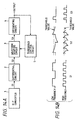
- Fig. 14A illustrates a block diagram of a conventional humidity meter
- Fig. 14B shows a waveform diagram of various parts of the humidity meter.
- Humidity meters have heretofore been used to detect humidity in various electronic apparatuses (e.g., copying machines, printers) and the like. One such humidity meter is shown.
- this humidity meter includes: the humidity-frequency converting circuit 1; the differentiating circuit 2; the waveform shaping circuit 3; the integrating circuit 4; and the threshold control circuit 5.
- This humidity meter is designed to produce an output (a detected humidity) from the integrating circuit 4.
- the humidity-frequency converting circuit 1 is formed by using an impedance variable humidity sensor that changes impedance exponentially in accordance with the change of humidity, and outputs a pulse train obtained by converting a change in humidity into a change in frequency.
- the differentiating circuit 2 is a circuit for receiving the output pulse train from the humidity-frequency converting circuit 1 and differentiating the received pulse train to generate a pulse train whose width is narrower than that of the aforementioned pulse train.
- the waveform shaping circuit 3 is a circuit (threshold circuit) for extracting a differentiated wave component whose threshold level is not less than a predetermined threshold level out of the differentiated wave and shaping the waveform of the extracted wave component.
- the integrating circuit 4 is designed to integrate the pulse train whose waveform has been shaped by the waveform shaping circuit 3.
- the threshold control circuit 5 controls the threshold level of the waveform shaping circuit 3 in response to the output voltage of the integrating circuit 4.
- Outputted from the humidity-frequency converting circuit 1 are a pulse train whose frequency f is low on the low humidity side and a pulse train whose frequency f is high on the high humidity side (see S1). Then, these pulse trains are differentiated by the differentiating circuit 2. Each of these differentiated pulse trains (see S2) is subjected to an extracting process in which component whose threshold level is not less than a predetermined threshold level is extracted, and each extracted component is then subjected to a waveform shaping process by the waveform shaping circuit 3 (see S3). These waveform-shaped pulse trains are thereafter integrated by the integrating circuit 4 to obtain a humidity meter output.
- the output voltage of the integrating circuit 4 is applied to the threshold control circuit 5 as a control voltage, and it is with this control voltage that the threshold control circuit 5 controls the threshold level of the waveform shaping circuit 3.
- the linearity of the humidity meter output is thus controlled by constantly optimizing a threshold level with respect to the magnitude of a humidity meter output in this way, and as a result, a humidity meter output with an excellent characteristic can be obtained.
- Fig. 15 is an exemplary conventional humidity meter circuit.
- the circuit configuration of a specific example of the humidity meter is illustrated in Fig. 15.
- This example is constructed by the differentiating circuit 2 of the capacitor C 1 and the resistor R 1 ; the waveform shaping circuit 3 of the gate (buffer gate) G 1 ; the threshold control circuit 5 of the transistor Tr and the resistors R 2 , R 3 ; and the integrating circuit 4 of the capacitor C 2 and the resistor R 5 .
- the output voltage of the capacitor C 2 constituting the integrating circuit 4 is applied to the base of the transistor Tr constituting the threshold control circuit 5 through the resistor R 4 .
- the base current of the transistor Tr is changed by the output voltage of the integrating circuit 4, and this changes the collector-emitter resistance of the transistor Tr in accordance with the output voltage of the integrating circuit 4.
- the potential on the input side of the gate G 1 is changed, thereby changing the threshold level.
- the aforementioned conventional humidity meter which is of high accuracy type, requires the humidity-frequency converting circuit, the differentiating circuit, the waveform shaping circuit, the integrating circuit, the threshold control circuit, and the like. Therefore, the humidity meter formed by integrating these individual circuits is disadvantageous in that the number of parts is large and that needs for downsizing, lightening, and cost reduction are not easily met.
- the oscillator circuit is essentially a pulse oscillator, the oscillation frequency of which depends upon the impedance of a humidity sensor.
- the active circuit comprises a differentiation circuit including a transistor as a first variable impedance element and a diode as a second variable impedance element coupled in series with the first variable impedance element.
- the capacity of this differentiation circuit connects the output of the pulse oscillator with the input of a wave-form shaping circuit as included in the active circuit.
- the output of the wave-form shaping circuit is connected via a feedback path with the base electrode of the transistor.
- the feedback path forms a first integrator and the output of the wave-form shaping circuit is connected via a second integrator with the output of the humidity meter.
- this prior art humidity meter operates in substantially the same art as the other prior art humidity meter as explained in connection with the pulse diagram in figure 14B.
- the aforementioned conventional humidity meter requires a large number of parts and uses expensive semiconductive elements particularly for the waveform shaping circuit and the threshold control circuit. Therefore, it is difficult to curtail the cost of manufacture, meaning that the humidity meter is expensive.
- a humidity meter comprises a power supply for providing an operating current, and an oscillator circuit including an as table multivibrator, a humidity sensor connected in a branch parallel to the bias resistor of the multivibrator and changing electric impedance thereof responsive to humidity, and an active circuit adapted to convert a change in humidity into a change in frequency, wherein said active circuit includes two field effect transistors electrically connected in complementary mode, with each transistor having the gate electrode connected to a common input, the drain electrode connected to a common output and the source electrode connected to a respective terminal of the power supply, said active cicuit converting the change in frequency into a change in operating current and outputting said operating current as a measure of humidity in ambient air at the humidity sensor.
- Fig. 1 is a diagram illustrative of the principle of the invention.
- reference characters C 11 to C 13 denote capacitors; R 11 , R 12 , R 17 , resistors; HS, a humidity sensor; T 1 , T 2 , terminals; Q 1 , a P-channel MOS-FET (MOS type field effect transistor); Q 2 , an N-channel MOS-FET; G 11 , a gate; and Ba, a power supply (battery).
- a humidity meter of the invention has the following configuration. That is, in Fig. 1, the circuit consisting of the gate G 11 , the resistor R 12 , and the capacitor C 12 constitutes astable multivibrator by a basic Schmitt trigger.
- An oscillator circuit is formed by connecting a humidity sensor circuit that is constructed of a series circuit in parallel to the resistor R 12 constituting the aforementioned basic Schmitt trigger-based astable multivibrator, the series circuit consisting of the capacitor C 11 , the resistor R 11 , and the humidity sensor HS.
- the humidity meter is constructed of this oscillator circuit.
- the humidity sensor HS is an impedance variable sensor.
- the impedance of the humidity sensor HS is high on the low humidity side, and drops rapidly on the high humidity side.
- the impedance of the humidity sensor HS changes nonlinearly with changing humidity.
- the gate G 11 is constructed of, e.g., a C-MOS integrated circuit (C-MOS logic circuit), and the output stage circuit thereof is such that two MOS-FETs Q 1 , Q 2 are connected to each other in totem pole form.
- Q 1 is a P-chancel MOS-FET
- Q 2 is an N-channel MOS-FET.
- a series circuit consisting of the resistor R 17 and the capacitor C 13 (capacitive load) is connected to the output of the gate G 11 (active circuit) in order to increase change in operating current due to change in oscillating frequency.
- the power supply Ba is connected to the terminals T 1 , T 2 .
- the voltage of the power supply Ba is applied to the output stage circuit consisting of Q 1 , Q 2 to cause an operating current i to flow.
- the oscillator circuit oscillates at a frequency corresponding to a change in humidity. That is, when the humidity surrounding the humidity sensor HS changes, so does the impedance of the humidity sensor HS. This change in impedance leads to a change in the time constant of the oscillator circuit, which in turn changes the oscillating frequency.
- the oscillating frequency is determined by the time constant of the capacitor C 12 , the resistor R 12 , and the humidity sensor circuit (C 11 + R 11 + HS). Further, since the humidity sensor HS exhibits high impedance on the low humidity side and drops the impedance drastically on the high humidity side, the oscillating frequency on the low humidity side is low and high on the high humidity side.
- the output stage circuit of the gate G 11 is operated in such a manner that when the input (point d) is high level "1", Q 1 turns off and Q 2 turns on and the output (point b) therefore becomes low level "0".
- the operating current i flowing through Q 1 , Q 2 at this instance is almost equal to zero.
- the operating current i changes depending on the operating frequency in the gate G 11 .
- the oscillating frequency changes in accordance with a change in humidity in the oscillator circuit. Since this change in frequency leads to a change in operating frequency of the gate G11, the operating current i changes in accordance with a change in humidity.
- the detection of a current corresponding to a change in humidity can be made by detecting the operating current i. That is, since the operating current i flowing through Q 1 , Q 2 of the gate G 11 changes in accordance with a change in impedance of the humidity sensor HS, humidity can be detected by detecting the operating current i.
- the operating current i becomes proportional to the oscillating frequency.
- the operating current i is increased at a low frequency (at a low humidity), the operating current i becomes too large at a high frequency (at a high humidity).
- the operating current is determined by the resistor R 17 with respect to frequencies not less than a frequency f 0 defined by the time constant of the resistor R 17 and the capacitor C 13 , thereby making the operating current not dependent on frequency.
- the increase in current on the high humidity side can be suppressed, thereby improving the linearity of the output characteristic.
- the humidity meter can be formed only of the oscillator circuit including the humidity sensor HS. Therefore, the number of parts is curtailed, which in turn contributes to the downsizing, lightening, and cost reduction of the humidity meter.
- the change in operating current due to a change in the oscillating frequency of the oscillator circuit can be increased by adding the current change increasing capacitor C 13 to the oscillator circuit constituting the humidity meter.
- the humidity meter can enjoy improved humidity detection accuracy and improved output characteristic.
- the rate of increase in operating current i on the high humidity side can be reduced by connecting the resistor R 17 in series with the current change increasing capacitor C 13 , thereby contributing to the improvement of the linearity of the output characteristic.
- Figs. 2A, 2B and 3 show the first embodiment.
- reference characters C 11 , C 12 denote capacitors; R 11 , R 12 , resistors; G 11 , a gate (inverter gate); Ba, a power supply (battery); HS, a humidity sensor; and T 1 , T 2 , terminals (humidity meter terminals).
- Fig. 2A is a circuit diagram of the humidity meter; and Fig. 2B is a diagram detailing part of Fig. 2A.
- the first embodiment is an example of a humidity meter utilizing an oscillator circuit that is constructed of a Schmitt trigger-based astable multivibrator (all the circuits are integrated).
- a circuit constructed of the gate G 11 , the resistor R 12 , and the capacitor C 12 is a basic Schmitt trigger-based astable multivibrator (basic oscillator circuit).
- the gate G 11 is a Schmitt trigger gate having a hysteresis characteristic
- the capacitor C 12 is an oscillating capacitor
- the resistor R 12 is a bias resistor.
- the oscillator circuit is formed by connecting a humidity sensor circuit in parallel to the resistor R 12 of the basic Schmitt trigger-based astable multivibrator (basic oscillator circuit).
- the humidity sensor circuit is constructed of a series circuit consisting of the capacitor C11, the resistor R11, and the humidity sensor HS. It is the oscillator circuit itself that constitutes the humidity meter in the first embodiment.
- the capacitor C 11 serves as a direct current interrupting capacitor (or direct current blocking capacitor), and the resistor R 11 serves as a resistor for correcting the characteristic of the humidity sensor HS on the high humidity side.
- the humidity sensor HS is an impedance variable sensor.
- the humidity sensor HS exhibits high impedance on the low humidity side, and the impedance drops drastically on the high humidity side (exponentially).
- the impedance of the humidity sensor HS changes nonlinearly with changing humidity.
- the gate G 11 is constructed of a C-MOS integrated circuit.
- the output stage circuit thereof is, as shown in diagram B, characterized as forming an inverter circuit in which two MOS-FETs Q 1 , Q 2 are connected in totem pole form.
- Q 1 is a P-channel MOS-FET
- Q 2 is an N-channel MOS-FET.
- the power supply (battery) Ba is connected to the terminals T 1 , T 2 of the humidity meter.
- the voltage of the power supply Ba is applied to the circuit consisting of Q 1 , Q 2 to activate the humidity meter.
- the oscillating operation of the oscillator circuit constituting the humidity meter is as follows. If it is assumed that the output (point b) of the gate G 11 (inverter) is high level "1", then the capacitor C 12 is charged through the resistor R 12 .
- This charging operation increases the terminal voltage of the capacitor C 12 , and when this voltage (point a) reaches an upper threshold voltage of the Schmitt trigger in the gate G 11 , the output (point b) of the gate G 11 goes low level "0".
- the humidity sensor circuit (C 11 + resistor R 11 + HS) is connected in parallel to the resistor R 12 , current flows through the humidity meter circuit when current flows through the resistor R 12 . As a result, the oscillator circuit oscillates at a frequency corresponding to a change in humidity.
- the oscillating frequency is determined by the time constant of the capacitor C 12 , the resistor R 12 , and the humidity sensor circuit (C 11 + R 11 + HS). Further, the humidity sensor HS exhibits high impedance on the low humidity side, and drops the impedance thereof drastically on the high humidity side. Therefore, the oscillating frequency of the humidity sensor HS is low on the low humidity side and high on the high humidity side.
- the output stage circuit of the C-MOS type IC is such that the two MOS-FETs Q 1 , Q 2 are connected to each other in totem pole form.
- this output stage circuit inverter
- Q 1 turns off and Q 2 turns on and the output (point b) therefore becomes low level "0”.
- the operating current i flowing through Q 1 , Q 2 at this instance is almost equal to zero.
- the operating current i changes depending on the operating frequency.
- the oscillating frequency changes in accordance with a change in humidity in the oscillator circuit shown in Fig. 2A as described above.
- Such change in frequency leads to a change in the operating frequency of the gate G 11 , which thus means that the operating current i changes in accordance with a change in humidity.
- the operating current i if the operating current i is detected, current corresponding to a change in humidity can be detected. That is, the operating current i flowing through Q 1 , Q 2 of the gate G 11 changes in accordance with a change in the impedance of the humidity sensor HS, so that humidity can be detected by detecting the operating current i.
- Fig. 3 is a diagram illustrative of the output characteristic of the first embodiment.
- the output characteristic (relative humidity-current characteristic) of the first embodiment will be described below with reference to Fig. 3.
- the horizontal axis indicates relative humidity (RH%)
- the vertical axis indicates operating current (A).
- the humidity meter according to the first embodiment is characterized as converting a change in humidity into a change in oscillating frequency, and further matching the change in frequency with a change in operating current i.
- the output characteristic of this case is, e.g., such as shown in Fig. 3.
- the operating current i is extremely small on the low humidity side, but the operating current i increases with increasing humidity and jumps drastically (exponentially) on the high humidity side. In this case, the relationship between humidity (relative humidity) and operating current i is nonlinear.
- humidity can be detected by detecting the operating current i. It may be noted that the operating current can be detected by, e.g., connecting a resistor to a negative terminal of the power supply circuit, causing the operating current i to be converted into voltage by this resistor, and outputting the converted voltage.
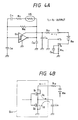
- Figs. 4A, 4B, 5A and 5B show the second embodiment.
- the same parts and components as those in Figs. 2 and 3 are denoted as the same reference characters.
- reference characters C 13 , C 14 , C 15 denote capacitors; and R 13 and R 14 , resistors.
- Figs. 4A is a circuit diagram of the humidity meter
- Fig. 4B is a diagram detailing part of Fig. 4A.
- the second embodiment is an example in which a change in operating current due to a change in oscillating frequency is amplified and in which the linearity of the output characteristic of the humidity meter is improved in the humidity meter according to the first embodiment.
- the humidity meter according to the second embodiment is formed by adding the capacitors C 13 , C 14 , C 15 , and the resistors R 13 , R 14 , and the like to the humidity meter according to the first embodiment.
- the capacitor C 13 is an operating current change increasing capacitor; the capacitors C 14 , C 15 are bypass capacitors; the resistor R 13 , an output limiting resistor; and the resistor R 14 , a current-voltage converting resistor (a resistor for converting the operating current i into voltage).
- terminals T 1 , T 2 , T 3 are arranged in such a manner that the power supply (battery) Ba is inserted between the terminals T 1 , T 3 and that the terminal T 2 is grounded (connected to GND). Further, a parallel circuit consisting of the current-voltage converting resistor R 14 and the bypass capacitor C 15 is inserted between the terminal T 3 and GND (the return of the power supply circuit).
- the output limiting resistor R 13 is connected to the terminal T 1 , so that the voltage is supplied to the gate G 11 through this resistor R 13 .
- the bypass capacitor C 14 is connected to the gate G 11 .
- MOS-FETs Q 1 , Q 2 are connected to the output stage of the gate G 11 (in the same manner as in the first embodiment), and the operating current change increasing capacitor C 13 is connected to the node of Q 1 , Q 2 (the output of the gate G 11 ).
- the capacitor C 13 repeats charging and discharging so as to increase the change in operating current i accompanied by the change in oscillating frequency (the operating current i is increased), whereas the resistor R 13 limits the operating current i that has been increased too much so as to improve the linearity of the output characteristic.
- terminals T 2 , T 3 serve as output terminals.
- the resistor R 14 converts the operating current i into voltage, and the converted voltage is outputted as an output voltage of the humidity meter (a voltage corresponding to the humidity).
- the capacitor C 13 is connected to the output of the gate G 11 so as to increase the change in operating current i.
- the operating current increasing effect of the capacitor C 13 will be described below.
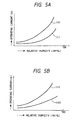
- Fig. 5A shows a first exemplary output characteristic
- Fig. 5B shows a second exemplary output characteristic.
- the output characteristic (relative humidity-operating current characteristic) of the second embodiment will be described below with reference to Figs. 5A and 5B.
- a curve (i) depicts the output characteristic of the humidity meter without the resistor R 13 and the capacitor C 13 (the same characteristic as that of the first embodiment); and a curve (ii) depicts the output characteristic of the humidity meter with only the capacitor C 13 connected thereto.
- the operating current i is small and the linearity of the output characteristic is not satisfactory as indicated by the curve (i).
- the capacitor C 13 is connected to the output of the gate G 11 , the capacitor C 13 is charged and discharged, and as a result, a change in operating current i due to a change in the oscillating frequency of the oscillator circuit is increased (the operating current i is increased) as indicated by the curve (ii).
- a curve (iii) depicts the output characteristic of the humidity meter with only the capacitor C 13 connected thereto (the same characteristic as that of the curve (ii) in Fig. 5A), and a curve (iv) depicts the output characteristic of the humidity meter with both the resistor R 13 and the capacitor C 13 connected thereto (the same connecting condition as that shown in Fig. 4A).
- the curve (iii) is obtained with a change in operating current i resulting from a change in the operating frequency of the oscillator circuit is increased.
- the resistor R 13 is additionally connected, the operating current i is limited by the resistor R 13 , thereby producing the output characteristic with improved linearity as shown by the curve (iv).
- Fig. 6 is a diagram illustrative of the third embodiment.
- the same parts and components as those in Figs. 2 to 5 are denoted as the same reference characters.
- Reference character Th denotes a thermistor.
- the third embodiment is an example in which the thermistor Th serves the double purpose of converting the operating current into voltage and making temperature compensation by replacing the resistor R 14 in the second embodiment with the thermistor Th.
- the humidity meter according to the second embodiment is characterized as increasing the oscillating frequency with increasing temperature. That is, the operating current i increases with increasing temperature.
- the thermistor Th exhibits high resistance at low temperatures, and reduces resistance with increasing temperature (negative temperature coefficient type). Therefore, although the operating current i increases with increasing temperature, the resistance of the thermistor Th decreases correspondingly, which in turn leaves the output voltage between the terminals T 2 , T 3 (the voltage of the thermistor Th) little changed with increasing temperature.
- the thermistor Th is connected to the negative terminal of the power supply circuit in this way, not only the operating current i can be converted into voltage (the output voltage of the humidity meter) but also an increase in operating current i due to an increase in ambient temperature can be compensated for by the thermistor Th. Since other configurational aspects of the third embodiment are the same as those of the second embodiment except for the thermistor Th, the description of such other aspects will be omitted.
- Figs. 7 to 9 show the fourth embodiment.
- the same parts and components as those in Figs. 2 to 6 are denoted as the same reference characters.
- Reference characters R 17 , R 18 denote resistors, and C 18 , a capacitor.
- Fig. 7 is a diagram illustrative of the fourth embodiment.
- the circuit configuration of a humidity sensor, which is the fourth embodiment of the invention, will be described with reference to Fig. 7.
- the fourth embodiment is an example in which the linearity of the output characteristic of the humidity meter according to the second embodiment (see Fig. 5) is further improved. As shown in Fig. 7, the fourth embodiment is characterized not only as connecting the resistor R 17 in series with the capacitor C 13 but also as adding an output smoothing filter consisting of the resistor R 18 and the capacitor C 18 to the humidity meter according to the second embodiment.
- the operating current i increases as described with reference to the second embodiment.
- the increase in operating current i brought about by the capacitor C 13 is proportional to the operating frequency of the gate G 11 .
- the output smoothing filter consisting of the resistor R 18 and the capacitor C 18 is added, the output voltage across the terminals T 2 , T 3 is smoothed.
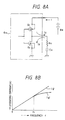
- Fig. 8A is a partially detailed diagram of Fig. 7, and Fig. 8B is a diagram illustrative of the output characteristic (frequency-operating current characteristic). The operation performed by the resistor R 17 and the capacitor C 13 will be described below with reference to Figs. 8A and 8B.
- the operating current i is proportional to the oscillating frequency. If the operating current i is increased at a low frequency (at a low humidity), the operating current i becomes too large at a high frequency (at a high humidity).
- the operating current i is regulated by the resistor R 17 with respect to frequencies not less than a frequency f 0 determined by the time constant of the circuit consisting of the resistor R 17 and the capacitor C 13 , which means that the operating current i is no longer dependent on frequency.
- a frequency f 0 determined by the time constant of the circuit consisting of the resistor R 17 and the capacitor C 13 .
- f 0 1/2 ⁇ CR
- C is the capacitance of the capacitor C 13
- R is the resistance of the resistor R 17 .
- a curve (i 1 ) depicts the output characteristic of the humidity meter with only the capacitor C 13 added thereto; and a curve (i 2 ) depicts the output characteristic of the humidity meter with the resistor R 17 and the capacitor C 13 added thereto.
- the output characteristic depicted by the curve (i 2 ) is characterized as exhibiting a controlled operating current i at high frequencies (high humidity side) compared with the output characteristic depicted by the curve (i 1 ). This contributes to improving the linearity of the output characteristic.
- Fig. 9 is a diagram illustrative of the output characteristic of the fourth embodiment.
- the output characteristic (relative humidity-operating current characteristic) of the fourth embodiment will be described below with reference to Fig. 9.
- the horizontal axis indicates relative humidity (RH%)
- the vertical axis indicates the operating current (A).
- a curve (i 7 ) depicts the output characteristic of the humidity meter with only the capacitor C 13 added thereto
- a curve (i 8 ) depicts the output characteristic of the humidity meter with a series circuit consisting of the resistor R 17 and the capacitor C 13 added thereto.
- the operating current i is increased when only the capacitor C 13 is added as depicted by the curve (i 7 ), but the linearity of the output characteristic is impaired (the operating current is excessively increased on the high humidity side).
- the series circuit consisting of the resistor R 17 and the capacitor C 13 is added, the increase in operating current on the high humidity side can be suppressed as depicted by the curve (i 8 ), and the linearity of the output characteristic can therefore be improved.
- Figs. 10 and 11 show the fifth embodiment.
- the same parts and components as those in Figs. 2 to 9 are denoted as the same reference characters.
- reference character R 19 denotes a resistor; and C 19 , a capacitor.
- Fig. 10 is a diagram illustrative of the fifth embodiment.
- the circuit configuration of a humidity meter according to the fifth embodiment will be described below with reference to Fig. 10.
- the fifth embodiment is an example in which in the fourth embodiment the series circuit consisting of the resistor R 17 and the capacitor C 13 is connected in parallel to a series circuit consisting of the resistor R 19 and the capacitor C 19 to further improve the linearity of the humidity meter.
- the series circuit consisting of the resistor R 17 and the capacitor C 13 (capacitive load) and the series circuit consisting of the resistor R 19 and the capacitor C 19 (capacitive load) are connected in parallel to each other to the output of the gate G 11 .
- the linearity of the output characteristic of the humidity meter is improved by these two series circuits. It may be noted that other configurational aspects are the same as those in the fourth embodiment, and the description of such other aspects will therefore be omitted.
- Fig. 11 is a diagram illustrative of the output characteristic of the fifth embodiment.
- the output characteristic (relative humidity-operating current characteristic) of the fifth embodiment will be described below with reference to Fig. 11.
- a curve (i 3 ) depicts the output characteristic of the humidity meter with the resistors (R 17 , R 19 ) and the capacitors (C 13 , C 19 ) not connected to the output of the gate G 11 (the same as in the first embodiment);
- a curve (i 4 ) depicts the output characteristic with only the series circuit consisting of the resistor R 17 and the capacitor C13 connected to the output of the gate G 11 (the same as in the fourth embodiment);
- a curve (i 5 ) depicts the output characteristic with only the series circuit consisting of the resistor R 19 and the capacitor C19 connected to the output of the gate G 11 ;
- a curve (i 6 ) depicts the output characteristic with the series circuit consisting of the resistor R 17 and the capacitor C13 and the series circuit consisting of the resistor R 19 and the capacitor C19 connected ((i 4 ) + (i 5 )).
- the operating currents i are suppressed in high frequencies (on the high humidity side) in the output characteristics (i 4 ), (i 5 ) compared with that in the output characteristic (i 3 ) as described in the fourth embodiment.
- the linearity of the output characteristic can be further improved.
- Fig. 12A is a circuit diagram of a humidity meter
- Fig. 12B is a diagram detailing part of Fig. 12A.
- the same parts and components as those in Figs. 2 to 11 are denoted as the same reference characters.
- reference characters G 12 , G 13 denote gates; R 20 , a resistor; and C 20 , a capacitor.
- the circuit configuration of the humidity meter according to the sixth embodiment will be described below with reference to Figs. 12A and 12B.
- the sixth embodiment is an example in which the configuration of the oscillator circuit in the fourth embodiment is modified.
- the oscillator circuit of the sixth embodiment is formed by connecting a humidity sensor circuit in parallel to the resistor R 12 of a basic oscillator circuit (a C-MOS gatebased astable multivibrator).
- the basic oscillator circuit consists of C-MOS gate ICs, the resistors R 20 , R 12 , and the capacitor C 20 , the C-MOS gate ICs being constructed of the gate G 12 (buffer gate) and the gate G 13 .
- the humidity sensor circuit consists of the humidity sensor HS, the resistor R 11 , and the capacitor C 11 .
- the resistor R 20 is a gate protecting resistor; and the resistor R 12 and the capacitor C 20 are elements for determining the oscillating frequency of the basic oscillator circuit.
- the capacitor C 11 is a direct current interrupting (or direct current blocking) capacitor; and the resistor R 11 is a resistor for characteristic compensation of the humidity sensor HS on the high humidity side.
- the aforementioned oscillator circuit oscillates at a frequency corresponding to a change in humidity in a manner similar to the respective embodiments.
- the oscillating frequency of this oscillator circuit is determined by the time constant based on the impedance of the capacitor C 20 , the resistor R 12 , and the humidity sensor circuit (HS + R 11 + C 11 ).
- the gate G 11 in the fourth embodiment is denoted as the gate G 13 in the sixth embodiment, the gate G 13 is substantially the same as the gate G11.
- a P-channel MOS-FET Q 1 and an N-channel MOS-FET Q 2 are connected in totem pole form to the output stage circuit of the gate G 13 .
- the impedance of the humidity sensor HS changes. This change in impedance changes the time constant, thereby changing the oscillating frequency. That is, the oscillator circuit oscillates at an oscillating frequency corresponding to the change in humidity.
- an operating current corresponding to the change in humidity flows through the gate G 13 in a manner similar to the fourth embodiment, and the output voltage (the output of the humidity meter) corresponding to the change in humidity can be obtained across the terminals T 2 , T 3 .
- Fig. 13 presents exemplary measured data of the embodiments.
- Fig. 13A shows first exemplary measured data
- Fig. 13B shows second exemplary measured data.
- the horizontal axis indicates relative humidity (RH%)
- the vertical axis indicates output voltage (V).
- the first exemplary measured data is an example in which measurements were made using the humidity meter according to the fourth embodiment (see Fig. 7).
- This humidity meter is characterized as connecting the series circuit consisting of the resistor R 17 and the capacitor C 13 to the output of the gate G 11 .
- the second exemplary measured data is an example in which measurements were made using the humidity meter according to the fifth embodiment (see Fig. 10).
- This humidity meter is characterized as connecting both the series circuit consisting of the resistor R 17 and the capacitor C 13 and the series circuit consisting of the resistor R 19 and the capacitor C 19 in parallel to the output of the gate G 11 .
- the data obtained as a result of such measurement is as shown in diagram B.
- This data exhibits an output characteristic with further improved linearity compared with the data shown in diagram A, particularly with the decreased output voltage on the high humidity side in diagram A being improved.
- the invention can provide the following advantages.
- the humidity meter can be constructed of only the oscillator circuit including a humidity sensor (see the first embodiment). Therefore, the humidity meter of the invention can dispense with a differentiating circuit, a waveform shaping circuit, an integrating circuit, and a threshold circuit as has been required by the conventional humidity meter, thereby decreasing the number of parts accordingly. As a result, the humidity meter can be downsized, lightened, and made inexpensively.
- the change in operating current due to a change in oscillating frequency can be increased by adding a current change increasing capacitor (C 13 ) to the oscillator circuit constituting the humidity meter (see the second and third embodiments).
- C 13 current change increasing capacitor
- an output limiting resistor (R 13 ) is inserted into the power supply circuit (see the second and third embodiments), so that the operating current is limited on the high humidity side to thereby improve the linearity of the output characteristic.
- a thermistor is connected to the negative terminal of the power supply circuit (see the third embodiment), not only the operating current is converted into voltage but also temperature compensation on the output side of the humidity meter can be made. Therefore, a stable output voltage can be obtained with respect to a change in temperature.
- the thermistor serves both as a current-voltage converter and a temperature compensator, the number of parts can be curtailed compared with humidity meters implementing such functions with separate parts. As a result, the humidity meter can be downsized and made inexpensively as well.
Landscapes
- Chemical & Material Sciences (AREA)
- Chemical Kinetics & Catalysis (AREA)
- Electrochemistry (AREA)
- Physics & Mathematics (AREA)
- Health & Medical Sciences (AREA)
- Life Sciences & Earth Sciences (AREA)
- Analytical Chemistry (AREA)
- Biochemistry (AREA)
- General Health & Medical Sciences (AREA)
- General Physics & Mathematics (AREA)
- Immunology (AREA)
- Pathology (AREA)
- Investigating Or Analyzing Materials By The Use Of Electric Means (AREA)
- Investigating Or Analyzing Materials By The Use Of Fluid Adsorption Or Reactions (AREA)
Claims (5)
- Feuchtigkeitsmesser, der umfasst:eine Energiequelle (Ba), die einen Betriebsstrom bereitstellt; undeine Oszillatorschaltung, die enthält:einen astabilen Multivibrator;einen Feuchtigkeitssensor (HS), der in einer Verzweigung parallel zu dem Vorspannungswiderstand (R12) des Multivibrators geschaltet ist und die elektrische Impedanz desselben in Reaktion auf Feuchtigkeit verändert, undeine aktive Schaltung (G11), die eine Veränderung der Feuchtigkeit in eine Veränderung der Frequenz umwandelt;
dadurch gekennzeichnet, dass:die aktive Schaltung (G11) zwei Feldeffekttransistoren (Q1, Q2) enthält, die elektrisch im Komplementärmodus geschaltet sind, wobei die Gate-Elektrode jedes Transistors mit einem gemeinsamen Eingang (d) verbunden ist, die Drain-Elektrode mit einem gemeinsam Ausgang (b) verbunden ist und die Source-Elektrode mit einem entsprechenden Anschluss der Energiequelle (Ba) verbunden ist;die aktive Schaltung (G11) die Veränderung der Frequenz in eine Veränderung des Betriebsstroms (i) umwandelt und den Betriebsstrom (i) als Maß der Feuchtigkeit in der Umgebungsluft an dem Feuchtigkeitssensor (HS) ausgibt. - Feuchtigkeitsmesser nach Anspruch 1, der des Weiteren einen Kondensator (C13) umfasst, der elektrisch mit einem Ausgang (b) der aktiven Schaltung (G11) als kapazitive Last verbunden ist, um die Veränderung des Betriebsstroms (i), die aus der Veränderung der Frequenz resultiert, zu verstärken.
- Feuchtigkeitsmesser nach Anspruch 1, der des Weiteren eine Reihenschaltung umfasst, die aus einem Kondensator (C13) und einem Widerstand (R17) besteht, die elektrisch mit einem Ausgang (b) der aktiven Schaltung (G11) als kapazitive Last verbunden sind, um die Veränderung des Betriebsstroms (i), die aus der Veränderung der Frequenz resultiert, zu verstärken und verbesserte Linearität des Ansprechverhaltens eines Sensors (HS) über ein breites Feuchtigkeitsspektrum zu gewährleisten.
- Feuchtigkeitsmesser nach Anspruch 1, der des Weiteren einen Thermistor (Th) umfasst, der elektrisch mit einem negativen Anschluss einer Energieversorgungsschaltung (Ba) verbunden ist, um die Veränderung des Betriebsstroms (i) in eine Veränderung der Spannung umzuwandeln und Temperaturausgleich von Feuchtigkeitsmessungen zu gewährleisten.
- Feuchtigkeitsmesser nach Anspruch 1, der des Weiteren eine Vielzahl von Reihenschaltungen umfasst, die jeweils aus einem Kondensator (C13, C19) und einem Widerstand (R17, R19) bestehen, die elektrisch parallel zu einem Ausgang (b) der aktiven Schaltung (G11) als kapazitive Lasten geschaltet sind, um die Veränderung des Betriebsstroms (i), die aus der Veränderung der Frequenz resultiert, zu verstärken.
Applications Claiming Priority (3)
| Application Number | Priority Date | Filing Date | Title |
|---|---|---|---|
| JP134705/94 | 1994-06-16 | ||
| JP13470594 | 1994-06-16 | ||
| JP6134705A JP2795807B2 (ja) | 1994-06-16 | 1994-06-16 | 湿度センサ |
Publications (2)
| Publication Number | Publication Date |
|---|---|
| EP0687903A1 EP0687903A1 (de) | 1995-12-20 |
| EP0687903B1 true EP0687903B1 (de) | 2001-11-21 |
Family
ID=15134676
Family Applications (1)
| Application Number | Title | Priority Date | Filing Date |
|---|---|---|---|
| EP95109267A Expired - Lifetime EP0687903B1 (de) | 1994-06-16 | 1995-06-14 | Feuchtigkeitsmessgerät |
Country Status (4)
| Country | Link |
|---|---|
| US (1) | US5652382A (de) |
| EP (1) | EP0687903B1 (de) |
| JP (1) | JP2795807B2 (de) |
| DE (1) | DE69523985T2 (de) |
Families Citing this family (9)
| Publication number | Priority date | Publication date | Assignee | Title |
|---|---|---|---|---|
| DE19711371C1 (de) * | 1997-03-19 | 1998-08-27 | Tekmar Elektronik Gmbh & Co | Einrichtung und Verfahren zur Schnee- und Eismeldung |
| TW418323B (en) * | 1998-02-19 | 2001-01-11 | Sumitomo Metal Ind | Capacitance detection system and method |
| WO2005114125A2 (en) * | 2004-05-13 | 2005-12-01 | Trintec Industries, Inc. | Electronic instrument movement/barometer |
| ITTO20040411A1 (it) * | 2004-06-21 | 2004-09-21 | Olivetti Jet S P A | Dispositivo di rilevamento di grandezze fisiche, particolarmente di umidita', e relativo metodo di rilevamento. |
| JP2006136086A (ja) * | 2004-11-04 | 2006-05-25 | Hitachi Ltd | 電流検知方法と電流検知装置及びこの電流検知装置を用いた電力変換装置並びにこの電力変換装置を用いた車両 |
| US7446660B2 (en) * | 2006-03-22 | 2008-11-04 | Intel Corporation | Passive environmental RFID transceiver |
| US9746438B2 (en) * | 2013-02-06 | 2017-08-29 | Veris Industries, Llc | Humidity sensor with temperature compensation |
| JP6549256B2 (ja) * | 2016-01-29 | 2019-07-24 | シャープ株式会社 | センサ装置 |
| US10364926B2 (en) | 2016-09-02 | 2019-07-30 | Veris Industries, Llc | Endcap for dry pressure insertion probe |
Family Cites Families (9)
| Publication number | Priority date | Publication date | Assignee | Title |
|---|---|---|---|---|
| JPS5144979U (de) * | 1974-10-01 | 1976-04-02 | ||
| JPS59168518A (ja) * | 1983-03-15 | 1984-09-22 | Toshiba Corp | 加湿器 |
| US4662220A (en) * | 1985-06-20 | 1987-05-05 | The United States Of America As Represented By The Administrator Of The National Aeronautics And Space Administration | Water-absorbing capacitor system for measuring relative humidity |
| US4816748A (en) * | 1986-08-28 | 1989-03-28 | Nippon Mining Co., Ltd. | Electronic thermohygrometer with square-wave pulse signal generator |
| JPH0725715Y2 (ja) * | 1988-08-31 | 1995-06-07 | 横河電機株式会社 | 周波数測定装置 |
| US4915816A (en) * | 1988-09-06 | 1990-04-10 | Parthasarathy Shakkottai | Polymer hygrometer for harsh environments |
| US5065625A (en) * | 1989-05-12 | 1991-11-19 | Tdk Corporation | Humidity meter |
| JP2851121B2 (ja) * | 1990-04-18 | 1999-01-27 | ティーディーケイ株式会社 | 湿度センサ |
| JP2536226Y2 (ja) * | 1991-12-13 | 1997-05-21 | ティーディーケイ株式会社 | 湿度センサ |
-
1994
- 1994-06-16 JP JP6134705A patent/JP2795807B2/ja not_active Expired - Fee Related
-
1995
- 1995-06-07 US US08/473,209 patent/US5652382A/en not_active Expired - Fee Related
- 1995-06-14 DE DE69523985T patent/DE69523985T2/de not_active Expired - Fee Related
- 1995-06-14 EP EP95109267A patent/EP0687903B1/de not_active Expired - Lifetime
Also Published As
| Publication number | Publication date |
|---|---|
| JP2795807B2 (ja) | 1998-09-10 |
| JPH085590A (ja) | 1996-01-12 |
| EP0687903A1 (de) | 1995-12-20 |
| DE69523985D1 (de) | 2002-01-03 |
| US5652382A (en) | 1997-07-29 |
| DE69523985T2 (de) | 2002-04-04 |
Similar Documents
| Publication | Publication Date | Title |
|---|---|---|
| US4878012A (en) | Charge balanced feedback transmitter | |
| EP1164697B1 (de) | Berührungsempfindlicher Schalter | |
| CN101419255B (zh) | 开关电源的占空比检测电路、检测方法及应用 | |
| CN113258916B (zh) | 电容触摸检测电路、芯片和电子设备 | |
| US5652382A (en) | Humidity meter | |
| US4879512A (en) | Circuit for processing a pseudo-oscillatory signal, especially for inductive proximity detectors | |
| JP2000055954A (ja) | 抵抗値測定回路及びその測定方法 | |
| US4603308A (en) | Temperature stable oscillator | |
| US20050099251A1 (en) | Circuit for detecting capacitance change in variable capacitance | |
| US5531097A (en) | Absolute humidity meter | |
| US20060158200A1 (en) | Capacitance measuring circuit | |
| SK102694A3 (en) | Connection of transducer | |
| JP2674369B2 (ja) | A/d変換器 | |
| KR100226873B1 (ko) | 디지털 습도계 및 습도조절기 회로 | |
| TW202533519A (zh) | 差分式讀取電路 | |
| JPS60624B2 (ja) | インピーダンス―周波数変換回路 | |
| JPH04351007A (ja) | 寄生容量に依存しない発振回路 | |
| JPH03123843A (ja) | 湿度センサ | |
| JP3272205B2 (ja) | 発振回路 | |
| JPH0722950A (ja) | Ad変換回路 | |
| JP3066921B2 (ja) | 浮遊静電容量の影響を補正したゲート発振器 | |
| JPH0449537Y2 (de) | ||
| JPH041562A (ja) | 湿度センサ | |
| JPH03125952A (ja) | 湿度センサ | |
| JPS584254Y2 (ja) | チヤ−ジアンプ |
Legal Events
| Date | Code | Title | Description |
|---|---|---|---|
| PUAI | Public reference made under article 153(3) epc to a published international application that has entered the european phase |
Free format text: ORIGINAL CODE: 0009012 |
|
| AK | Designated contracting states |
Kind code of ref document: A1 Designated state(s): DE FR GB |
|
| 17P | Request for examination filed |
Effective date: 19960612 |
|
| 17Q | First examination report despatched |
Effective date: 19990401 |
|
| GRAG | Despatch of communication of intention to grant |
Free format text: ORIGINAL CODE: EPIDOS AGRA |
|
| GRAG | Despatch of communication of intention to grant |
Free format text: ORIGINAL CODE: EPIDOS AGRA |
|
| GRAH | Despatch of communication of intention to grant a patent |
Free format text: ORIGINAL CODE: EPIDOS IGRA |
|
| GRAH | Despatch of communication of intention to grant a patent |
Free format text: ORIGINAL CODE: EPIDOS IGRA |
|
| GRAA | (expected) grant |
Free format text: ORIGINAL CODE: 0009210 |
|
| AK | Designated contracting states |
Kind code of ref document: B1 Designated state(s): DE FR GB |
|
| REG | Reference to a national code |
Ref country code: GB Ref legal event code: IF02 |
|
| REF | Corresponds to: |
Ref document number: 69523985 Country of ref document: DE Date of ref document: 20020103 |
|
| ET | Fr: translation filed | ||
| PGFP | Annual fee paid to national office [announced via postgrant information from national office to epo] |
Ref country code: FR Payment date: 20020610 Year of fee payment: 8 |
|
| PGFP | Annual fee paid to national office [announced via postgrant information from national office to epo] |
Ref country code: GB Payment date: 20020612 Year of fee payment: 8 |
|
| PGFP | Annual fee paid to national office [announced via postgrant information from national office to epo] |
Ref country code: DE Payment date: 20020619 Year of fee payment: 8 |
|
| PLBE | No opposition filed within time limit |
Free format text: ORIGINAL CODE: 0009261 |
|
| STAA | Information on the status of an ep patent application or granted ep patent |
Free format text: STATUS: NO OPPOSITION FILED WITHIN TIME LIMIT |
|
| 26N | No opposition filed | ||
| PG25 | Lapsed in a contracting state [announced via postgrant information from national office to epo] |
Ref country code: GB Free format text: LAPSE BECAUSE OF NON-PAYMENT OF DUE FEES Effective date: 20030614 |
|
| PG25 | Lapsed in a contracting state [announced via postgrant information from national office to epo] |
Ref country code: DE Free format text: LAPSE BECAUSE OF NON-PAYMENT OF DUE FEES Effective date: 20040101 |
|
| GBPC | Gb: european patent ceased through non-payment of renewal fee |
Effective date: 20030614 |
|
| PG25 | Lapsed in a contracting state [announced via postgrant information from national office to epo] |
Ref country code: FR Free format text: LAPSE BECAUSE OF NON-PAYMENT OF DUE FEES Effective date: 20040227 |
|
| REG | Reference to a national code |
Ref country code: FR Ref legal event code: ST |