EP0689860B1 - Appareil pour collecter de la poussière - Google Patents
Appareil pour collecter de la poussière Download PDFInfo
- Publication number
- EP0689860B1 EP0689860B1 EP95303707A EP95303707A EP0689860B1 EP 0689860 B1 EP0689860 B1 EP 0689860B1 EP 95303707 A EP95303707 A EP 95303707A EP 95303707 A EP95303707 A EP 95303707A EP 0689860 B1 EP0689860 B1 EP 0689860B1
- Authority
- EP
- European Patent Office
- Prior art keywords
- duct
- outlet
- passages
- filter elements
- dust collecting
- Prior art date
- Legal status (The legal status is an assumption and is not a legal conclusion. Google has not performed a legal analysis and makes no representation as to the accuracy of the status listed.)
- Expired - Lifetime
Links
- 239000000428 dust Substances 0.000 title claims description 39
- 239000007789 gas Substances 0.000 claims description 72
- 238000005406 washing Methods 0.000 claims description 45
- 230000006698 induction Effects 0.000 claims description 34
- 238000005192 partition Methods 0.000 claims description 19
- 239000000919 ceramic Substances 0.000 claims description 12
- 238000011144 upstream manufacturing Methods 0.000 claims description 4
- 229910010293 ceramic material Inorganic materials 0.000 claims description 3
- 210000003850 cellular structure Anatomy 0.000 claims description 2
- 238000004891 communication Methods 0.000 claims description 2
- 239000010419 fine particle Substances 0.000 description 12
- 230000007246 mechanism Effects 0.000 description 7
- 239000002245 particle Substances 0.000 description 4
- 238000012986 modification Methods 0.000 description 3
- 230000004048 modification Effects 0.000 description 3
- 230000002093 peripheral effect Effects 0.000 description 3
- 230000003068 static effect Effects 0.000 description 3
- 238000002474 experimental method Methods 0.000 description 2
- 230000000717 retained effect Effects 0.000 description 2
- 230000001413 cellular effect Effects 0.000 description 1
- 238000002485 combustion reaction Methods 0.000 description 1
- 238000010276 construction Methods 0.000 description 1
- 238000007599 discharging Methods 0.000 description 1
- 230000000694 effects Effects 0.000 description 1
- 230000002708 enhancing effect Effects 0.000 description 1
- 230000001788 irregular Effects 0.000 description 1
- 239000011236 particulate material Substances 0.000 description 1
- 238000000926 separation method Methods 0.000 description 1
- 239000007787 solid Substances 0.000 description 1
Images


Classifications
-
- B—PERFORMING OPERATIONS; TRANSPORTING
- B01—PHYSICAL OR CHEMICAL PROCESSES OR APPARATUS IN GENERAL
- B01D—SEPARATION
- B01D46/00—Filters or filtering processes specially modified for separating dispersed particles from gases or vapours
- B01D46/24—Particle separators, e.g. dust precipitators, using rigid hollow filter bodies
- B01D46/2403—Particle separators, e.g. dust precipitators, using rigid hollow filter bodies characterised by the physical shape or structure of the filtering element
- B01D46/2418—Honeycomb filters
-
- B—PERFORMING OPERATIONS; TRANSPORTING
- B01—PHYSICAL OR CHEMICAL PROCESSES OR APPARATUS IN GENERAL
- B01D—SEPARATION
- B01D46/00—Filters or filtering processes specially modified for separating dispersed particles from gases or vapours
- B01D46/0039—Filters or filtering processes specially modified for separating dispersed particles from gases or vapours with flow guiding by feed or discharge devices
- B01D46/0047—Filters or filtering processes specially modified for separating dispersed particles from gases or vapours with flow guiding by feed or discharge devices for discharging the filtered gas
- B01D46/0049—Filters or filtering processes specially modified for separating dispersed particles from gases or vapours with flow guiding by feed or discharge devices for discharging the filtered gas containing fixed gas displacement elements or cores
-
- B—PERFORMING OPERATIONS; TRANSPORTING
- B01—PHYSICAL OR CHEMICAL PROCESSES OR APPARATUS IN GENERAL
- B01D—SEPARATION
- B01D46/00—Filters or filtering processes specially modified for separating dispersed particles from gases or vapours
- B01D46/56—Filters or filtering processes specially modified for separating dispersed particles from gases or vapours with multiple filtering elements, characterised by their mutual disposition
- B01D46/58—Filters or filtering processes specially modified for separating dispersed particles from gases or vapours with multiple filtering elements, characterised by their mutual disposition connected in parallel
-
- B—PERFORMING OPERATIONS; TRANSPORTING
- B01—PHYSICAL OR CHEMICAL PROCESSES OR APPARATUS IN GENERAL
- B01D—SEPARATION
- B01D2273/00—Operation of filters specially adapted for separating dispersed particles from gases or vapours
- B01D2273/20—High temperature filtration
Definitions
- the present invention relates to a dust collecting apparatus for purifying various exhaust gases containing dust, and more particularly to a dust collecting apparatus constructed to collect dust from the exhaust gases introduced therein for discharging the gases in a clean condition.
- JP-A-4-271806 (1992) and JP-A-4-354506 (1992) is a dust collecting apparatus of this kind which includes a plurality of ceramic filter elements aligned in parallel within a housing, each of the filter elements being made of porous ceramic material and having a thin walled cellular structure formed with a plurality of axially extending passages separated from each other by thin partition walls, wherein a first group of the axial passages are closed at first ends in a checker pattern and open at their other ends to introduce therein exhaust gases to be purified, while a second group of the axial passages are open at first ends to discharge purified gascs therefrom and closed at their other ends in a checker pattern, the housing being provided with an outlet duct located at a downstream side of the filter assembly.
- exhaust gases to be purified are introduced into the first group of the axial inlet passages at an upstream side of the filter assembly so that the thin partition walls of the filter elements act to collect dust from the exhaust gases permeating therethrough from the first group of the axial inlet passages into the second group of the axial outlet passages thereby to purify the exhaust gases.
- the purified gases are discharged from the housing through the outlet duct while fine particles of the dust are accumulated on the surfaces of the partition walls.
- washing gas under pressure is intermittently supplied into the filter assembly through the outlet duct and flows into the second group of the axial outlet passages to flow into the first group of the axial inlet passages through the partition walls.
- the accumulated fine particles are separated from the partition walls.
- the outlet duct is in the form of a spout duct formed with a plurality of equally spaced jet nozzles.
- the spout duct is spaced in a predetermined distance from the downstream end of the filter assembly to introduce washing gas under high pressure into the second group of the axial outlet passages therefrom for washing the filter elements.
- the reverse washing cfficicncy of the filter elements is greatly affected by the pressure of washing gas applied to the second group of the axial outlet passages. It is, therefore, required to increase the spout pressure of the washing gas as higher as possible for enhancing the reverse washing efficiency of the filter elements.
- the washing gas is directly applied to the downstream side of the filter elements from the jet nozzles of the spout duct.
- a portion of the washing gas is discharged outwardly from a discharge duct provided on the housing for discharge of the purified gases. This causes a decrease of the pressure of the washing gas introduced into the second group of the outlet passages and fluctuation of the spout pressure of the jet nozzles, resulting in irregular separation of the accumulated dust at the partition walls.
- WO91/00769 shows a particle separator for separating particulate material from high temperature gases, having an array of porous filter tubes held in support plates in a housing.
- the tubes are each open at both ends. Gas being treated passes in via the upper ends of the filter tubes and through the tube walls into outlet zones of the housing surrounding the tubes. Collected particles are back-washed by pulses of air ejected from ejector pipes whose ejection ends are located in outlet throats of the outlet zones. The particles fall through the lower ends of the filter tubes into a collection zone.
- the ends of the open-ended porous filter tubes are fixed to openings in the first support plate and the second support plate.
- the present invention provides a dust collecting apparatus as set out in claim 1.
- a dust collecting apparatus which includes a ceramic filter assembly 20 disposed within a housing 10 and a reverse washing mechanism 30 for the filter assembly 20.
- the housing 10 is composed of a housing body 11 of rectangular cross-section and a pyramidal hopper 12 assembled with the bottom portion of housing body 11.
- a cylindrical furnace body 13 is connected to the bottom end of hopper 12.
- the housing body 11 has a discharge duct 11a formed at an upper side portion thereof for discharge of purified gases, while the hopper 12 has an inlet duct 12a formed at its peripheral wall for supply of exhaust gases to be purified.
- the ceramic filter assembly 20 is arranged between the inlet duct 12a and the discharge duct 11a.
- the ceramic filter assembly 20 is composed of a plurality of filter elements 21 aligned in parallel and clamped by a pair of side plates 22a, 22b.
- the clamped filter elements 21 are carried by vertical support members 23.
- the side plates 22a, 22b are supported by a lower rectangular flange 11b of housing body 11 at their lower ends and fixed to side walls of housing body 11 at their upper portions by means of fastening bolts 11d to retain the filter assembly 20 in place.
- the ceramic filter elements 21 each are made of porous ceramic material and have a thin-walled cellular or honeycomb structure of square cross-section formed with a plurality of axially extending passages separated from each other by thin partition walls.
- a first group of the axial passages are in the form of inlet passages closed at their upper ends in a checker pattern and opened downwardly at their lower ends to introduce therein exhaust gases to be purified.
- a second group of the axial passages are in the form of outlet passages closed their lower ends in a checker pattern and opened upwardly at their upper ends to discharge purified gases therefrom.
- Cover bodies 31, 32 each in the form of a bottom open box are secured to upper ends of the side plates 22a, 22b and spaced a predetermined distance from the upper end of filter assembly 20 to form closed chambers R above the upper end of filter assembly 20.
- the cover bodies 31, 32 are provided with outlet ducts 31a, 32a which are mounted on the upper walls of cover bodies 31, 32 and extend vertically upwardly.
- washing gas induction ducts 33, 34 Arranged above the cover bodies 31, 32 are washing gas induction ducts 33, 34 which are mounted on an upper wall of housing body 11 and extend vertically therethrough in such a manner that the inner opening end of each induction duct 33, 34 is opposed to the upper opening end of the respective outlet duct 31a, 32a and spaced a predetermined distance therefrom.
- the dust collecting apparatus has been installed to purify exhaust gases discharged from a combustion device such as a diesel engine in a factory plant
- the exhaust gases under pressure are supplied into the interior of housing 10 through the inlet duct 12a at the upstream side of the filter assembly 20 and introduced into the inlet passages of filter elements 21.
- the thin partition walls of filter elements 21 act to collect fine particles of dust from the exhaust gases permeating therethrough into the outlet passages of filter elements 21.
- the exhaust gases are purified and flow as purified gascs into the closed chambers R at the downstream side of the filter elements 21.
- the purified gases flow into an upper space of the housing 11 from the closed chambers R through the outlet ducts 31a, 32a and are discharged therefrom through the discharge duct 11a outwardly, while the fine particles of dust are accumulate on the surfaces of the partition walls.
- an electromagnetic valve (not shown) of the reverse washing mechanism is intermittently opened under control of an electric control apparatus (not shown) to supply washing gas under high pressure into the closed chambers R through the induction ducts 33, 34 and outlet ducts 31a, 32a for a predetermined time.
- the pressure in the closed chambers R is increased to a high pressure, and the washing gas is supplied under high pressure into the outlet passages of filter elements 21 to flow into the inlet passages of filter elements 21 through the partition walls of filter elements 21.
- This increases a difference in pressure between the outlet and inlet passages of filter elements 21.
- the accumulated fine particles are uniformly separated from the partition walls of filter elements 21 and fall into the furnace body 13.
- the washing gas is temporarily retained in the closed chambers R to increase the internal pressure of the closed chambers R.
- the washing gas is supplied under high pressure into the outlet passages of filter elements 21. Accordingly, the amount of the washing gas discharged from the discharge duct 11a is extremely reduced, and the internal pressure of the closed chambers R is efficiently increased. This is useful to enhance the reverse washing efficiency of the filter assembly 20 and to greatly reduce the consumption of the washing gas.
- the static pressure applied to the outlet passages of filter elements 21 from the closed chambers R is made uniform such that the accumulated fine particles are uniformly separated from the partition walls of filter elements 21.
- FIG. 2 Illustrated in Fig. 2 is a modification of the dust collecting apparatus of Fig.1, wherein the same components and portions as those in the above embodiment are designated by the same reference numerals.
- outlet ducts 31b, 32b corresponding to the outlet ducts 31a, 32a in the above embodiment are mounted on side walls of the cover bodies 31, 32 and extended horizontally therethrough into the closed chambers R.
- Induction ducts 35, 36 corresponding with the washing gas induction ducts 33, 34 in the above embodiment are mounted on side walls of the housing body 11 and extend horizontally therethrough into the interior of housing body 11 in such a manner that the inner opening end of each induction duct 35, 36 is opposed to the outer opening end of the respective outlet ducts 31b, 32b and spaced a predetermined distance therefrom.
- FIG. 4 Illustrated in Fig. 4 is another embodiment of a filter assembly unit which may be used in a collecting apparatus as illustrated in Fig. 3.
- the apparatus has an upright cylindrical housing 14 provided therein with a plurality of circumferentially spaced lateral support beams 15 arranged at vertically equally spaced plural steps to form a plurality of circumferentially spaced vertical gas induction passages r1 along an internal peripheral surface of the housing 14 and a vertical discharge passage r2 at the center of the housing 14, and plural sets of circumferentially spaced filter assembly units 40 vertically mounted on each of the support beams 15 in such a manner that the filter assembly units 40 are exposed at their outer ends to the gas induction passage r1 and at their inner ends to the discharge passage r2.
- the cylindrical housing 14 is provided at its upper side walls with inlet ducts 14a and at its upper end with a discharge duct 14b.
- exhaust gases containing dust are supplied into gas induction passages r1 through the inlet ducts 14a and introduced into the respective filter assembly units 40 under a difference in pressure between the gas induction passages r1 and discharge passage r2.
- purified gases are discharged from the filter assembly units 40 into the discharge passage r2, while fine particles of dust are accumulated in the filter assembly units 40.
- the purified gases are discharged from the discharge passage r2 through the discharge duct 14b outwardly.
- the filter assembly units 40 each are composed of a plurality of ceramic filter elements 40a horizontally arranged in parallel to one another and mounted within a casing 42.
- the ceramic filter elements 40a each are formed in the same construction as those in the dust collecting apparatus shown in Figs. 1 and 2.
- the filter assembly units 40 each are provided with a reverse washing mechanism 40b which includes a cover body 43 secured to an opening end of the casing 42 to form a closed chamber R in open communication with the outlet passages of the filter elements 40a.
- the cover body 43 has an outlet duct 43a integrally formed at its upper wall and extended in a predetermined distance into the interior of the closed chamber R.
- a washing gas induction duct 44 Arranged above the cover body 43 is a washing gas induction duct 44 which is opposed to an upper opening end of the outlet duct 43a and spaced therefrom in a predetermined distance.
- the induction duct 44 is extended outwardly through the peripheral wall of cylindrical housing 14 and connected to a source of washing gas under pressure (not shown).
- exhaust gases to be purified are introduced into the ceramic filter assembly units 40 from the inlet ducts 14a through the gas induction passages r1 and purified by the filter elements in the ceramic filter assembly units 40.
- the purified gases are introduced into the discharge passage r2 through the closed chambers R and outlet ducts 43a and discharged outwardly from the discharge duct 14b.
- fine particles of dust contained in the exhaust gases are collected at the partition walls of the filter elements and accumulated on the surfaces of the partition walls.
- each electromagnetic valve (not shown) of the reverse washing mechanisms is opened to supply washing gas under high pressure into the closed chambers R through the induction ducts 44 of the filter assembly units 40 for a predetermined time.
- the pressure in the closed chambers R is increased to a high pressure, and the washing gas is supplied under high pressure into the outlet passages of the filter elements in the respectively filter assembly units 40 to flow into the inlet passages of the filter elements through the partition walls.
- This increases a difference in pressure between the outlet and inlet passages of the filter elements.
- the accumulated fine particles are uniformly separated from the patition walls of the filter elements and fall into a container chamber (not shown) from the hopper 14c.
- the washing gas is temporarily retained in the closed chambers R to increase the internal pressure of the closed chambers R.
- the washing gas is supplied under high pressure into the outlet passages of the filter elements without causing any discharge into the discharge passage r2. This is useful to enhance the reverse washing efficiency of the filter assembly units 40 and to greatly reduce consumption of the washing gas.
- the internal pressure of the closed chambers R is uniformly increased by the washing gas supplied from the induction duct 44, the static pressure applied to the outlet passages of the filter elements from the closed chambers R is made uniform such that the accumulated fine particles are uniformly separated from the partition walls of the filter elements.
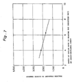
- a maximum pressure in the closed chambers R is shown in relation to a distance X(mm) between the inner opening ends (i.e. outlet ends) of induction ducts 35, 36 and the inner ends (i.e. upstream ends in the flow direction of purified gas) of outlet ducts 31b, 32b in the dust collecting apparatus shown in Fig. 2.
- Fig. 6 there is schematically illustrated the arrangement of induction duct 36 and outlet duct 32b in the dust collection apparatus of Fig. 2 to demonstrate a result of experiments conducted under conditions listed in the following table.
- curves c1, c2 were plotted in the case that the pressure P0 at the induction duct 36 was 1 kg/cm 2 G
- curves d1, d2 were plotted in the case that the pressure P0 at the induction duct 36 was 2 kg/cm 2 G
- curves e1, e2 were plotted in the case that the pressure P0 at the induction duct 36 was 3 kg/cm 2 G.
- the solid curves c1, d1, e1 were obtained in a condition where a ratio (s0/s1) of the cross-sectional area s0 of the outlet duct 32b to the cross-sectional area s1 of the induction duct 36 was 6.25.
- the broken curves c2, d2, e2 were obtained in a condition where the ratio (s0/s1) of the cross-sectional areas s0 and s1 was 4.0.
- a maximum pressure Pmax(mm Aq) obtained under the following condition is illustrated in relation to the ratio s0/s1 of the cross-sectional areas.
- the distance X between the inner opening end of the induction duct 36 and the inner opening end of the outlet duct 32b is determined to be more than a predetermined distance, a maximum pressure Pmax in the closed chamber R becomes constant regardlessly of the length a, b of the outlet duct 32b.
- the distance X is determined to be more than 200mm, and it is preferable that the cross-sectional area ratio s0/s1 of the outlet duct 23b and induction duct 36 is determined to be less than 10.
Landscapes
- Chemical & Material Sciences (AREA)
- Chemical Kinetics & Catalysis (AREA)
- Physics & Mathematics (AREA)
- Geometry (AREA)
- Filtering Of Dispersed Particles In Gases (AREA)
Claims (3)
- Appareil de collecte de poussière comprenant un boítier (11, 14) présentant un conduit d'entrée (12a, 14a) et un conduit d'évacuation (11a, 14b), un ou plusieurs éléments filtrants en céramique (21, 40a) disposés dans ledit boítier, ledit élément filtrant céramique ou chacun desdits éléments filtrants en céramique (21) étant réalisé en une matière céramique poreuse et ayant une structure cellulaire à paroi mince présentant une pluralité de passages s'étendant axialement séparés les uns des autres par de minces parois de séparation, où un premier groupe de passages axiaux se présente sous la forme de passages d'entrée fermés à des premières extrémités et ouverts à leurs autres extrémités pour introduire dans ceux-ci des gaz fournis par ledit conduit d'entrée à purifier, tandis qu'un second groupe de passages axiaux se présente sous la forme de passage de sortie ouverts à des premières extrémités pour évacuer les gaz purifiés de ceux-ci à travers ledit conduit d'évacuation et fermés à leurs autres extrémités, au moins un corps de recouvrement (31, 32, 43) étant prévu qui est assemblé avec lesdits éléments filtrants (21) à un côté aval de celui-ci pour former au moins une chambre fermée (R) en communication ouverte avec les passages de sortie desdits éléments filtrants (21) et présentant au moins un conduit de sortie (31a, 32a, 31b, 32b, 43a) qui s'ouvre depuis l'intérieur de ladite chambre fermée (R) pour permettre l'évacuation des gaz purifiés à travers celui-ci de ladite chambre fermée (R) vers ledit conduit d'évacuation (11a), et où ledit boítier (11) présente au moins un conduit d'admission (33, 34, 35, 36, 44) ayant une extrémité de sortie à l'extérieur dudit conduit de sortie et opposée audit conduit de sortie (31a, 32a, 31b, 32b, 43a) dudit corps de recouvrement, pour l'introduction du gaz de lavage sous pression dans ladite chambre fermée (R), le conduit de sortie et le conduit d'admission ayant chacun une zone constante en section transversale, et le rapport de la zone en section transversale dudit conduit de sortie (31a, 32a, 31b, 32b) et dudit conduit d'admission (33, 34, 35, 36) étant inférieur à 10.
- Appareil de collecte de poussière selon la revendication 1, où la distance entre l'extrémité de sortie dudit conduit d'admission (33, 34, 35, 36) et l'extrémité dudit conduit de sortie (31a, 32a, 31b ou 32b) qui est en amont dans la direction d'écoulement du gaz purifié est supérieure à 200 mm.
- Appareil de collecte de poussière selon la revendication 1 ou 2, où ledit conduit de sortie (31b, 32b) s'étend dans l'intérieur de ladite chambre fermée (R).
Applications Claiming Priority (3)
| Application Number | Priority Date | Filing Date | Title |
|---|---|---|---|
| JP6118498A JP3066247B2 (ja) | 1994-05-31 | 1994-05-31 | 集塵装置 |
| JP11849894 | 1994-05-31 | ||
| JP118498/94 | 1994-05-31 |
Publications (2)
| Publication Number | Publication Date |
|---|---|
| EP0689860A1 EP0689860A1 (fr) | 1996-01-03 |
| EP0689860B1 true EP0689860B1 (fr) | 2001-08-16 |
Family
ID=14738163
Family Applications (1)
| Application Number | Title | Priority Date | Filing Date |
|---|---|---|---|
| EP95303707A Expired - Lifetime EP0689860B1 (fr) | 1994-05-31 | 1995-05-31 | Appareil pour collecter de la poussière |
Country Status (4)
| Country | Link |
|---|---|
| US (1) | US5593471A (fr) |
| EP (1) | EP0689860B1 (fr) |
| JP (1) | JP3066247B2 (fr) |
| DE (1) | DE69522153T2 (fr) |
Families Citing this family (9)
| Publication number | Priority date | Publication date | Assignee | Title |
|---|---|---|---|---|
| JPH09206536A (ja) * | 1996-02-07 | 1997-08-12 | Ngk Insulators Ltd | 集塵装置におけるフィルタの逆洗方法 |
| US6364921B1 (en) * | 2000-06-30 | 2002-04-02 | Donaldson Company, Inc. | Air filter assembly for filtering air having particulate matter |
| US20040020365A1 (en) * | 2002-04-22 | 2004-02-05 | Carsten Hansen | Filter |
| JP4243122B2 (ja) * | 2003-03-27 | 2009-03-25 | メタウォーター株式会社 | 逆洗装置 |
| US8635861B2 (en) * | 2009-12-23 | 2014-01-28 | Caterpillar Inc. | Exhaust aftertreatment system |
| JP5925617B2 (ja) * | 2012-06-28 | 2016-05-25 | メタウォーター株式会社 | セラミックフィルタ集塵装置 |
| EP2698189B1 (fr) * | 2012-08-17 | 2019-08-07 | Pall Corporation | Module de filtre et système de filtre le comprenant |
| CN111249811B (zh) * | 2020-01-18 | 2022-03-29 | 王和 | 一种医用雾化自清洗过滤网的空气过滤瓶 |
| KR102880947B1 (ko) * | 2025-03-17 | 2025-11-12 | (주)세라컴 | 고온집진기 |
Family Cites Families (25)
| Publication number | Priority date | Publication date | Assignee | Title |
|---|---|---|---|---|
| US3963467A (en) * | 1973-03-08 | 1976-06-15 | Rolschau David W | Dust filter apparatus |
| US4046526A (en) * | 1976-01-12 | 1977-09-06 | Aerodyne Development Corporation | Bag collector for dirt with selective half-bag cleaning |
| CH625969A5 (fr) * | 1977-07-15 | 1981-10-30 | Buehler Ag Geb | |
| US4161389A (en) * | 1978-04-07 | 1979-07-17 | Procedyne, Inc. | Fluidized bed calcining system |
| US4409009A (en) * | 1978-11-20 | 1983-10-11 | Nordson Corporation | Powder spray booth |
| DE2906353C3 (de) * | 1979-02-19 | 1983-02-03 | Gebrüder Bühler AG, 9240 Uzwil | Verfahren und Filtersteueranlage zur zyklischen Gegenspülung membranventilbetätigter Filterschläuche |
| US4504293A (en) * | 1980-11-06 | 1985-03-12 | Donaldson Company, Inc. | Self-cleaning air filter |
| US4343631A (en) * | 1981-01-30 | 1982-08-10 | Westinghouse Electric Corp. | Hot gas particulate removal |
| JPS58132524U (ja) * | 1982-02-26 | 1983-09-07 | 西山 信六 | 集塵システムにおける粉塵分離装置 |
| US4525184A (en) * | 1983-05-20 | 1985-06-25 | Electric Power Research Institute, Inc. | Vertically tiered particle filtering apparatus |
| US4661131A (en) * | 1983-11-07 | 1987-04-28 | Howeth David Franklin | Backflushed air filters |
| JPS60172328A (ja) * | 1984-02-16 | 1985-09-05 | Hokoku Kikai Kk | 集塵機の運転方法 |
| GB8821717D0 (en) * | 1988-09-16 | 1988-10-19 | Atomic Energy Authority Uk | Air filter |
| US4904287A (en) * | 1988-12-22 | 1990-02-27 | Electric Power Research Institute | Compact ceramic tube filter array high-temperature gas filtration |
| US5062872A (en) * | 1989-05-12 | 1991-11-05 | Pneumafil Corporation | Air filter with horizontal filter elements |
| WO1991000769A1 (fr) * | 1989-07-12 | 1991-01-24 | A. Ahlstrom Corporation | Appareil et procede de separation de matiere particulaire des gaz a temperature elevee |
| DE8914966U1 (de) * | 1989-12-21 | 1990-02-15 | Deutsche Babcock Anlagen Ag, 4200 Oberhausen | Vorrichtung zum Entstauben eines Gasstromes |
| US5143530A (en) * | 1990-10-22 | 1992-09-01 | Westinghouse Electric Corp. | Filtering apparatus |
| US5078760A (en) * | 1991-02-11 | 1992-01-07 | Westinghouse Electric Corp. | Separation of particulate from gases produced by combustion of fossil material |
| JPH0661416B2 (ja) * | 1991-02-25 | 1994-08-17 | 日本碍子株式会社 | 排ガス処理装置 |
| JPH0661417B2 (ja) * | 1991-05-29 | 1994-08-17 | 日本碍子株式会社 | ガス処理装置 |
| US5348568A (en) * | 1992-02-05 | 1994-09-20 | Asahi Glass Company Ltd. | Filtering method of flue gas of a boiler and a filter apparatus for hot gas |
| JP2718615B2 (ja) * | 1993-03-12 | 1998-02-25 | 日本碍子株式会社 | 高温ガス用集塵装置 |
| US5458665A (en) * | 1993-07-12 | 1995-10-17 | A. Ahlstrom Corporation | Apparatus for filtering gases |
| DE4324065C2 (de) * | 1993-07-17 | 2001-05-31 | Reimelt Dietrich Kg | Filter, insbesondere Feinstaub-Entlüftungsfilter |
-
1994
- 1994-05-31 JP JP6118498A patent/JP3066247B2/ja not_active Expired - Fee Related
-
1995
- 1995-05-30 US US08/452,692 patent/US5593471A/en not_active Expired - Lifetime
- 1995-05-31 DE DE69522153T patent/DE69522153T2/de not_active Expired - Lifetime
- 1995-05-31 EP EP95303707A patent/EP0689860B1/fr not_active Expired - Lifetime
Also Published As
| Publication number | Publication date |
|---|---|
| DE69522153D1 (de) | 2001-09-20 |
| DE69522153T2 (de) | 2002-04-11 |
| US5593471A (en) | 1997-01-14 |
| JPH07323207A (ja) | 1995-12-12 |
| JP3066247B2 (ja) | 2000-07-17 |
| EP0689860A1 (fr) | 1996-01-03 |
Similar Documents
| Publication | Publication Date | Title |
|---|---|---|
| US5228892A (en) | Exhaust emission control device | |
| US5601626A (en) | Support construction of filter element in dust collecting apparatus | |
| KR950007911B1 (ko) | 고온 가스로부터의 입자 물질 분리 장치 | |
| KR100348168B1 (ko) | 필터와 정전기적 분리기의 조합 | |
| US4588423A (en) | Electrostatic separator | |
| EP0689860B1 (fr) | Appareil pour collecter de la poussière | |
| EP0762923B1 (fr) | Elimination des accumulations de cendres dans des filtres ceramiques | |
| EP0788826A1 (fr) | Système de contrÔle pour le mécanisme de rinçage à contre-courant de un dispositif de captation de poussières | |
| US5536285A (en) | Ceramic filtering of gases | |
| US5205850A (en) | Particular filter | |
| US5094673A (en) | Apparatus for dedusting a gas stream | |
| US5284498A (en) | Cylindrical filters in a tube sheet for cleaning high temperature gases | |
| EP0704234B1 (fr) | Appareil d'enlèvement de poussière | |
| KR101591568B1 (ko) | 고효율 집진기 | |
| RU2147915C1 (ru) | Регенерируемый фильтр для тонкой очистки газов от пыли | |
| WO2000062936A1 (fr) | Systeme et procede pour la purification de gaz en ecoulement | |
| RU2283687C1 (ru) | Фильтровальная установка для очистки горячих газов | |
| EP0620034B1 (fr) | Appareil de collection de poussière pour gaz à haute température | |
| RU2179879C1 (ru) | Рукавный фильтр | |
| SE443928B (sv) | Filteranordning for rening av gasformigt medium | |
| SU1762988A1 (ru) | Зернистый фильтр дл очистки газов | |
| RU2860335C1 (ru) | Устройство для очистки газа или жидкости | |
| RU2699637C2 (ru) | Регенерируемый фильтр для очистки парогазовой смеси | |
| KR910004772B1 (ko) | 순환 유동상 반응기 및 그 반응실로부터 나오는 가스에 함유된 고체의 분리 방법 | |
| RU1789292C (ru) | Бинарный циклон |
Legal Events
| Date | Code | Title | Description |
|---|---|---|---|
| PUAI | Public reference made under article 153(3) epc to a published international application that has entered the european phase |
Free format text: ORIGINAL CODE: 0009012 |
|
| AK | Designated contracting states |
Kind code of ref document: A1 Designated state(s): DE FR GB |
|
| 17P | Request for examination filed |
Effective date: 19960607 |
|
| 17Q | First examination report despatched |
Effective date: 19971124 |
|
| GRAG | Despatch of communication of intention to grant |
Free format text: ORIGINAL CODE: EPIDOS AGRA |
|
| GRAG | Despatch of communication of intention to grant |
Free format text: ORIGINAL CODE: EPIDOS AGRA |
|
| GRAH | Despatch of communication of intention to grant a patent |
Free format text: ORIGINAL CODE: EPIDOS IGRA |
|
| GRAH | Despatch of communication of intention to grant a patent |
Free format text: ORIGINAL CODE: EPIDOS IGRA |
|
| GRAA | (expected) grant |
Free format text: ORIGINAL CODE: 0009210 |
|
| AK | Designated contracting states |
Kind code of ref document: B1 Designated state(s): DE FR GB |
|
| REF | Corresponds to: |
Ref document number: 69522153 Country of ref document: DE Date of ref document: 20010920 |
|
| REG | Reference to a national code |
Ref country code: GB Ref legal event code: IF02 |
|
| ET | Fr: translation filed | ||
| PLBE | No opposition filed within time limit |
Free format text: ORIGINAL CODE: 0009261 |
|
| STAA | Information on the status of an ep patent application or granted ep patent |
Free format text: STATUS: NO OPPOSITION FILED WITHIN TIME LIMIT |
|
| 26N | No opposition filed | ||
| PGFP | Annual fee paid to national office [announced via postgrant information from national office to epo] |
Ref country code: GB Payment date: 20140528 Year of fee payment: 20 |
|
| PGFP | Annual fee paid to national office [announced via postgrant information from national office to epo] |
Ref country code: DE Payment date: 20140528 Year of fee payment: 20 Ref country code: FR Payment date: 20140509 Year of fee payment: 20 |
|
| REG | Reference to a national code |
Ref country code: DE Ref legal event code: R071 Ref document number: 69522153 Country of ref document: DE |
|
| REG | Reference to a national code |
Ref country code: GB Ref legal event code: PE20 Expiry date: 20150530 |
|
| PG25 | Lapsed in a contracting state [announced via postgrant information from national office to epo] |
Ref country code: GB Free format text: LAPSE BECAUSE OF EXPIRATION OF PROTECTION Effective date: 20150530 |