EP0690780B1 - Procede de production d'objets tridimensionnels - Google Patents
Procede de production d'objets tridimensionnels Download PDFInfo
- Publication number
- EP0690780B1 EP0690780B1 EP94912502A EP94912502A EP0690780B1 EP 0690780 B1 EP0690780 B1 EP 0690780B1 EP 94912502 A EP94912502 A EP 94912502A EP 94912502 A EP94912502 A EP 94912502A EP 0690780 B1 EP0690780 B1 EP 0690780B1
- Authority
- EP
- European Patent Office
- Prior art keywords
- process according
- layer
- subregions
- solidified
- region
- Prior art date
- Legal status (The legal status is an assumption and is not a legal conclusion. Google has not performed a legal analysis and makes no representation as to the accuracy of the status listed.)
- Expired - Lifetime
Links
Images
Classifications
-
- B—PERFORMING OPERATIONS; TRANSPORTING
- B29—WORKING OF PLASTICS; WORKING OF SUBSTANCES IN A PLASTIC STATE IN GENERAL
- B29C—SHAPING OR JOINING OF PLASTICS; SHAPING OF MATERIAL IN A PLASTIC STATE, NOT OTHERWISE PROVIDED FOR; AFTER-TREATMENT OF THE SHAPED PRODUCTS, e.g. REPAIRING
- B29C64/00—Additive manufacturing, i.e. manufacturing of three-dimensional [3D] objects by additive deposition, additive agglomeration or additive layering, e.g. by 3D printing, stereolithography or selective laser sintering
- B29C64/40—Structures for supporting 3D objects during manufacture and intended to be sacrificed after completion thereof
-
- B—PERFORMING OPERATIONS; TRANSPORTING
- B33—ADDITIVE MANUFACTURING TECHNOLOGY
- B33Y—ADDITIVE MANUFACTURING, i.e. MANUFACTURING OF THREE-DIMENSIONAL [3D] OBJECTS BY ADDITIVE DEPOSITION, ADDITIVE AGGLOMERATION OR ADDITIVE LAYERING, e.g. BY 3D PRINTING, STEREOLITHOGRAPHY OR SELECTIVE LASER SINTERING
- B33Y10/00—Processes of additive manufacturing
-
- Y—GENERAL TAGGING OF NEW TECHNOLOGICAL DEVELOPMENTS; GENERAL TAGGING OF CROSS-SECTIONAL TECHNOLOGIES SPANNING OVER SEVERAL SECTIONS OF THE IPC; TECHNICAL SUBJECTS COVERED BY FORMER USPC CROSS-REFERENCE ART COLLECTIONS [XRACs] AND DIGESTS
- Y10—TECHNICAL SUBJECTS COVERED BY FORMER USPC
- Y10S—TECHNICAL SUBJECTS COVERED BY FORMER USPC CROSS-REFERENCE ART COLLECTIONS [XRACs] AND DIGESTS
- Y10S264/00—Plastic and nonmetallic article shaping or treating: processes
- Y10S264/59—Processes in which a partial cure is involved
Definitions
- the present invention relates to a method for manufacturing a three-dimensional object according to the generic term of Claim 1.
- EP-A-0 429 196 describes a method according to the preamble of Claim 1 known. Avoiding the occurrence of delay and deformation in the formed object is however in the in described in this document achieved by a layer is exposed in such a way that a boundary vector is exposed and the interior by means of different Techniques is partially exposed.
- WO 92/20505 also describes a method for manufacturing of a three-dimensional object.
- WO 92/08200 also describes a method according to the preamble of claim 1 known. Stages by successive Layers are created on the surface through special techniques of additional exposure of the step area balanced.
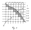
- the invention is further illustrated by an embodiment explained with reference to the figure, which is in schematic Representation of a section through part of the object shows in a layer plane.
- FIG. 1 A partial view of an example of a selected layer is shown in the figure on the basis of which the invention The procedure should first be described in principle.
- line 1 the contour of the to be manufactured Object in the layer.
- the area of the layer is grid-like in a variety of square or rectangular Individual areas or voxels i, j .... i + 6, j + 6 with one Side length from 0.1 to 5mm, preferably 0.5 to 2mm, divided.
- the coordinate data of contour 1 and the individual Individual areas are available in a computer that receives the radiation the shift controls. A comparison is made in the computer the contour data with the coordinate data of the individual areas.
- this individual area becomes a core area 2 assigned; however, it is found that a single area, for example the individual area i, j, of the contour 1 is cut, then this single area becomes an envelope area 3 assigned. This results in a narrower Envelope area 3, which along the contour line 1 with a on average approximately corresponding to the side length of the individual areas Width extends.
- the calculation is preferably carried out exclusively in the computer the core area 2; the envelope area 3 is then through Subtraction of the individual areas of core area 2 from the whole body calculated.
- the core area 2 all individual areas are marked which are fully inside the Body section, i.e. the contour line 1.
- the individual areas are assigned to Shell or core, however, not just two-dimensional, like Explained in principle above, but three-dimensionally, in order to defined thickness of the envelope area 3 in all three spatial directions to obtain.
- contour line 1 corresponds to a contour surface and when calculating the core area all individual areas marked that fully inside this contour area lie.
- Each individual area i, j contains in addition to the Information about the current shift including the corresponding one Information about previous shifts.
- the predetermined number depends on the desired number Shell thickness and the spatial distance between the individual areas; with layer thicknesses of 0.1mm and a shell thickness of 0.5mm For example, this number is 5.
- the same consideration also applies to subsequent layers: it only those individual areas are included in the core that in a given number of subsequent layers also belong to the core or would belong to it.
- the individual areas in the core area 2 only along closed Solidify lines, so that hollow structures such as Honeycomb structures result in which are still liquid or powdery material is included, which after the Solidification of the object either drained or by post-hardening is solidified.
- This method is particularly suitable to avoid thermal expansion, for example for melting molds, and also for direct production of molds.
- the inverted object is converted into a enveloping cuboid. This creates a negative form on the one in the manner described above Disassembly into shell and core is made.
- the radiation is carried out in such a way that that there is a high degree of polymerization and thus a high Strength with low tendency to warp results.
- the envelope area 3 there is high accuracy and quality of the surface on the contour 1. This is done the radiation or solidification in the envelope area 3 all over either in the form of side by side Hatching lines or one or more side by side Contour lines, i.e. the contour 1 for example as Polyline following line groups. Also a combination of these line types in a layer or in one on top of the other Layering is possible.
- the radiation in the core area 2 and in the envelope area 3 one single layer can be simultaneously or in succession by appropriate control using a single or also several light beams or laser beams take place, whereby the layer thickness in core area 2 and envelope area 3 is equal to.
- a number N of layers of the envelope region 3 solidify, where N is an integer.
- the material in the core area 2 initially remains liquid or powdery with a layer thickness that is N times the layer thickness of the Envelope area 3 corresponds. With the Nth layer too this thick layer of the core area by correspondingly intense Irradiation solidified. This can save time for the production of the core and thus for the production of the object can be significantly reduced.
- the core is not fully solidified, it is advantageous to provide openings in the shell through which the Core remaining liquid or powdery material after the solidification of the object can flow off. For example so that in every nth layer Breakthroughs of the envelope area 3 are provided, so are large enough to allow material to flow out, but do not affect the surface quality.
- the particular advantage of the described method lies in that through the superimposed envelope areas 3 a relatively stable shell is made that it allowed the core area by means of a default minimizing technique without losing stability of the object suffers. For example, it's only because of this Cover possible on the connecting webs between the individual Dispense with cells or hollow structures in the core area. Furthermore, the manufacturing time is significantly reduced that at the core, which covers the vast majority of the Object volume forms, is only partially solidified.
Landscapes
- Chemical & Material Sciences (AREA)
- Engineering & Computer Science (AREA)
- Manufacturing & Machinery (AREA)
- Materials Engineering (AREA)
- Physics & Mathematics (AREA)
- Mechanical Engineering (AREA)
- Optics & Photonics (AREA)
- Heating, Cooling, Or Curing Plastics Or The Like In General (AREA)
Claims (17)
- Procédé de fabrication d'un objet tridimensionnel, dans lequel l'objet est réalisé par le durcissement consécutif de chaque couche d'un matériau durcissable, liquide ou en poudre, sous l'action d'un rayonnement électromagnétique, chaque couche étant divisée en une zone centrale intérieure (2) et une zone de bordure extérieure (3) et l'effet du rayonnement étant commandé différemment dans la zone centrale (2) et dans la zone de bordure (3), afin d'obtenir des propriétés différentes dans les deux zones, caractérisé en ce que la zone de bordure (3) est déterminée selon une méthode tridimensionnelle par la soustraction des zones individuelles dans la zone centrale (2) de l'ensemble du corps.
- Procédé selon la revendication 1, caractérisé en ce que l'effet du rayonnement dans la zone centrale (2) est exercé de telle sorte que la déformation de l'objet pendant et après le durcissement est réduite au minimum et en ce que l'effet du rayonnement dans la zone de bordure (3) est exercé de manière à obtenir une surface si possible lisse et précise.
- Procédé selon la revendication 2, caractérisé en ce que des zones partielles de la zone centrale (2), séparées et écartées les unes des autres, sont durcies, et en ce que, le cas échéant, les zones intermédiaires entre les zones partielles seront également durcies après le durcissement des zones partielles d'une couche ou après le durcissement de toutes les zones partielles de l'objet.
- Procédé selon la revendication 2 ou 3, caractérisé en ce que l'on durcit dans la zone centrale (2) des bandes séparées, qui sont reliées aux bandes contiguës et sous-jacentes par une construction d'appui.
- Procédé selon la revendication 2, caractérisé en ce que l'on durcit dans la zone centrale (2) d'abord des zones partielles d'une couche, qui à cet effet seront reliées aux zones partielles sous-jacentes de la couche précédemment durcie, pour former des cellules à plusieurs couches, en ce que les zones partielles sont ensuite reliées aux zones partielles contiguës de la même couche par le durcissement des zones de liaison étroites entre les zones partielles sous forme de barrettes de liaison, et en ce que l'on durcit enfin les zones intermédiaires entre les zones partielles.
- Procédé selon la revendication 5, caractérisé en ce que les zones de liaison ne sont durcies qu'après un temps d'attente qui correspond a un retrait du matériau dans les zones partielles égal à au moins une valeur donnée.
- Procédé selon la revendication 3, caractérisé en ce que les zones partielles sont réalisées de manière à obtenir des structures alvéolaires, de préférence des structures en nids d'abeilles.
- Procédé selon l'une quelconque des revendications précédentes, caractérisé en ce que, dans la zone de bordure (3), des zones partielles situées jointivement les unes à côté des autres sont durcies.
- Procédé selon l'une quelconque des revendications précédentes, caractérisé en ce que l'effet de rayonnement est exercé dans la zone de bordure (3) le long d'une ou plusieurs lignes qui tracent le bord extérieur de la zone de bordure ou sont parallèles à celui-ci.
- Procédé selon l'une quelconque des revendications précédentes, caractérisé en ce que l'épaisseur de la couche dans la zone de bordure (3) a été choisie inférieure à celle dans la zone centrale.
- Procédé selon la revendication 10, caractérisé en ce que tout d'abord un nombre entier N de couches dans la zone de bordure (3) sont durcies et ensuite une couche dans la zone centrale (2), dont l'épaisseur est égale à N fois l'épaisseur des couches de la zone de bordure, est durcie.
- Procédé selon l'une quelconque des revendications précédentes, caractérisé en ce que l'on définit pour la zone de bordure (3) des éléments volumiques de l'objet dans une couche, lesquels sont situés à l'intérieur de cette couche à une distance donnée du bord de l'objet.
- Procédé selon la revendication 12, caractérisé en ce que ces éléments volumiques sont définis en contact avec le bord ou le contour de l'objet ou coupés par ledit bord ou contour dans une couche et/ou dans un nombre donné de couches déposées précédemment et/ou ultérieurement à cette couche.
- Procédé selon l'une quelconque des revendications précédentes, caractérisé en ce que l'on choisit pour la zone de bordure (3) une épaisseur comprise entre 0,1 et 5 mm, de préférence entre 0,5 et 2 mm.
- Procédé selon l'une quelconque des revendications précédentes, caractérisé en ce que des orifices sont réalisés dans la zone de bordure (3), par lesquels le matériau non durci dans la zone centrale (2) peut s'écouler.
- Procédé selon l'une quelconque des revendications 1 à 15, caractérisé en ce que la zone de bordure (3) présente une épaisseur définie, sa largeur dans une couche étant égale en moyenne à pratiquement la longueur d'un côté des zones individuelles.
- Mise en oeuvre d'un procédé selon l'une quelconque des revendications 1 à 15, pour la fabrication de moules en fonte, dans lequel l'objet inverti est posé dans un parallélépipède formant une gaine, afin d'en obtenir un moule négatif, sur lequel sera exécuté la division en zone de bordure et zone centrale.
Applications Claiming Priority (3)
| Application Number | Priority Date | Filing Date | Title |
|---|---|---|---|
| DE4309524 | 1993-03-24 | ||
| DE4309524A DE4309524C2 (de) | 1993-03-24 | 1993-03-24 | Verfahren zum Herstellen eines dreidimensionalen Objekts |
| PCT/EP1994/000900 WO1994021446A1 (fr) | 1993-03-24 | 1994-03-22 | Procede de production d'objets tridimensionnels |
Publications (2)
| Publication Number | Publication Date |
|---|---|
| EP0690780A1 EP0690780A1 (fr) | 1996-01-10 |
| EP0690780B1 true EP0690780B1 (fr) | 1998-07-01 |
Family
ID=6483701
Family Applications (1)
| Application Number | Title | Priority Date | Filing Date |
|---|---|---|---|
| EP94912502A Expired - Lifetime EP0690780B1 (fr) | 1993-03-24 | 1994-03-22 | Procede de production d'objets tridimensionnels |
Country Status (5)
| Country | Link |
|---|---|
| US (1) | US5932059A (fr) |
| EP (1) | EP0690780B1 (fr) |
| JP (1) | JPH08504139A (fr) |
| DE (2) | DE4309524C2 (fr) |
| WO (1) | WO1994021446A1 (fr) |
Cited By (2)
| Publication number | Priority date | Publication date | Assignee | Title |
|---|---|---|---|---|
| DE102016007817A1 (de) | 2016-06-23 | 2017-12-28 | Daimler Ag | Verfahren zum Glätten einer Oberfläche eines Bauteils |
| US10625374B2 (en) | 2013-02-27 | 2020-04-21 | SLM Solutions Group AG | Method for producing work pieces having a tailored microstructure |
Families Citing this family (71)
| Publication number | Priority date | Publication date | Assignee | Title |
|---|---|---|---|---|
| JP3215881B2 (ja) * | 1994-05-27 | 2001-10-09 | イーオーエス ゲゼルシャフト ミット ベシュレンクテル ハフツング イレクトロ オプティカル システムズ | 鋳込み技術に使用される方法 |
| DE4440397C2 (de) * | 1994-11-11 | 2001-04-26 | Eos Electro Optical Syst | Verfahren zum Herstellen von Gußformen |
| DE4436695C1 (de) * | 1994-10-13 | 1995-12-21 | Eos Electro Optical Syst | Verfahren zum Herstellen eines dreidimensionalen Objektes |
| WO1997014549A1 (fr) * | 1995-10-13 | 1997-04-24 | Eos Gmbh Electro Optical Systems | Procede de fabrication d'un objet en 3d |
| DE19606128A1 (de) * | 1996-02-20 | 1997-08-21 | Eos Electro Optical Syst | Vorrichtung und Verfahren zum Herstellen eines dreidimensionalen Objektes |
| DE19929199A1 (de) * | 1999-06-25 | 2001-01-18 | Hap Handhabungs Automatisierun | Verfahren und Vorrichtung zum Herstellen eines dreidimensionalen Objektes |
| JP3687475B2 (ja) * | 2000-03-28 | 2005-08-24 | 松下電工株式会社 | 立体形状物体の造形方法 |
| DE10042134C2 (de) * | 2000-08-28 | 2003-06-12 | Concept Laser Gmbh | Verfahren zur Herstellung von dreidimensionalen Sinter-Werkstücken |
| US6699424B2 (en) * | 2001-06-29 | 2004-03-02 | 3D Systems, Inc. | Method for forming three-dimensional objects |
| EP1441897B1 (fr) * | 2001-10-30 | 2006-08-09 | CL Schutzrechtsverwaltungs GmbH | Procede de production de pieces frittees tridimensionnelles |
| DE10219984C1 (de) * | 2002-05-03 | 2003-08-14 | Bego Medical Ag | Vorrichtung und Verfahren zum Herstellen frei geformter Produkte |
| DE10219983B4 (de) * | 2002-05-03 | 2004-03-18 | Bego Medical Ag | Verfahren zum Herstellen von Produkten durch Freiform-Lasersintern |
| CA2494588C (fr) * | 2002-05-10 | 2009-06-30 | Nagoya Industrial Science Research Institute | Modele tridimensionnel |
| SE524439C2 (sv) * | 2002-12-19 | 2004-08-10 | Arcam Ab | Anordning samt metod för framställande av en tredimensionell produkt |
| SE524421C2 (sv) * | 2002-12-19 | 2004-08-10 | Arcam Ab | Anordning samt metod för framställande av en tredimensionell produkt |
| SE524420C2 (sv) * | 2002-12-19 | 2004-08-10 | Arcam Ab | Anordning samt metod för framställande av en tredimensionell produkt |
| GB0317387D0 (en) * | 2003-07-25 | 2003-08-27 | Univ Loughborough | Method and apparatus for combining particulate material |
| DE10336561B4 (de) | 2003-08-07 | 2019-05-02 | Lim Laserinstitut Mittelsachsen Gmbh | Verfahren zum Herstellen eines Miniaturkörpers oder mikrostrukturierten Körpers |
| US20050087897A1 (en) * | 2003-10-23 | 2005-04-28 | Nielsen Jeffrey A. | Systems and methods for reducing waste in solid freeform fabrication |
| US7569174B2 (en) * | 2004-12-07 | 2009-08-04 | 3D Systems, Inc. | Controlled densification of fusible powders in laser sintering |
| US7829000B2 (en) * | 2005-02-25 | 2010-11-09 | Hewlett-Packard Development Company, L.P. | Core-shell solid freeform fabrication |
| US8044437B1 (en) | 2005-05-16 | 2011-10-25 | Lsi Logic Corporation | Integrated circuit cell architecture configurable for memory or logic elements |
| DE102005027311B3 (de) * | 2005-06-13 | 2006-11-02 | Trumpf Werkzeugmaschinen Gmbh + Co. Kg | Verfahren zur Herstellung eines dreidimensionalen Formkörpers |
| DE102005030067A1 (de) * | 2005-06-27 | 2006-12-28 | FHS Hochschule für Technik, Wirtschaft und soziale Arbeit St. Gallen | Verfahren und Vorrichtung zur Herstellung eines dreidimensionalen Gegenstandes durch ein generatives 3D-Verfahren |
| DE102006008332B4 (de) * | 2005-07-11 | 2009-06-04 | Fraunhofer-Gesellschaft zur Förderung der angewandten Forschung e.V. | Verfahren zur Herstellung einer funktionellen Baueinheit und funktionelle Baueinheit |
| DE102005049886A1 (de) * | 2005-10-17 | 2007-04-19 | Sirona Dental Systems Gmbh | Verfahren zur Herstellung eines Zahnersatzteils |
| DE102005050665A1 (de) | 2005-10-20 | 2007-04-26 | Bego Medical Gmbh | Schichtweises Herstellungsverfahren mit Korngrößenbeeinflussung |
| ES2328430B1 (es) * | 2006-04-06 | 2010-09-16 | Moises Mora Garcia | Maquina de fabricacion de protesis dentales y maxilofaciales a partir de un modelo digital tridimensional mediante aplicacion directa de laser y sinterizacion, y procedimiento de operacion de dicha maquina. |
| EP1880830B1 (fr) * | 2006-07-19 | 2011-12-21 | Envisiontec GmbH | Procédé et dispositif pour la fabrication d'un article tridimensionel, un ordinateur et un support d'information associés |
| DK2052693T4 (da) † | 2007-10-26 | 2021-03-15 | Envisiontec Gmbh | Proces og fri-formfabrikationssystem til at fremstille en tredimensionel genstand |
| DE102007057129B4 (de) | 2007-11-24 | 2010-07-22 | Hochschule Mittweida (Fh) | Verfahren und Einrichtung zur Hochleistungs-Mikrobearbeitung eines Körpers oder einer Pulverschicht mit einem Laser hoher Brillanz |
| RU2386517C1 (ru) * | 2008-08-07 | 2010-04-20 | Российская Федерация, от имени которой выступает государственный заказчик - Министерство промышленности и торговли Российской Федерации (Минпромторг России) | Способ спекания при лазерном послойном порошковом синтезе объемных деталей |
| US8738166B2 (en) | 2009-02-24 | 2014-05-27 | Panasonic Corporation | Method for manufacturing three-dimensional shaped object and three-dimensional shaped object obtained by the same |
| US20120132627A1 (en) | 2009-04-28 | 2012-05-31 | Bae Systems Plc | Additive layer fabrication method |
| US9278483B2 (en) | 2009-04-28 | 2016-03-08 | Bae Systems Plc | Additive layer fabrication method |
| CN102458722B (zh) | 2009-06-23 | 2015-03-18 | 松下电器产业株式会社 | 三维形状造型物的制造方法及由其获得的三维形状造型物 |
| DE102009043597A1 (de) * | 2009-09-25 | 2011-04-07 | Siemens Aktiengesellschaft | Verfahren zum Herstellen eines markierten Gegenstandes |
| GB201016169D0 (en) * | 2010-09-27 | 2010-11-10 | Materialise Nv | Method for reducing differential shrinkage in stereolithography |
| DE102011089194A1 (de) * | 2011-12-20 | 2013-06-20 | BAM Bundesanstalt für Materialforschung und -prüfung | Verfahren zur Fertigung eines kompakten Bauteils sowie mit dem Verfahren herstellbares Bauteil |
| DE102012212587A1 (de) | 2012-07-18 | 2014-01-23 | Eos Gmbh Electro Optical Systems | Vorrichtung und Verfahren zum schichtweisen Herstellen eines dreidimensionalen Objekts |
| DE102013212803A1 (de) | 2013-07-01 | 2015-01-08 | Eos Gmbh Electro Optical Systems | Verfahren zum Herstellen eines dreidimensionalen Objekts |
| JP6229155B2 (ja) * | 2013-10-03 | 2017-11-15 | パナソニックIpマネジメント株式会社 | 三次元形状造形物の製造方法 |
| EP2875897B1 (fr) * | 2013-11-21 | 2016-01-20 | SLM Solutions Group AG | Procédé et dispositif de commande d'un système d'irradiation pour produire une pièce tridimensionnelle |
| JP6146294B2 (ja) * | 2013-12-25 | 2017-06-14 | トヨタ自動車株式会社 | 三次元形状造形物の製造方法 |
| WO2015133137A1 (fr) | 2014-03-05 | 2015-09-11 | パナソニックIpマネジメント株式会社 | Procédé de production d'article moulé tridimensionnel |
| TWI609769B (zh) * | 2014-06-03 | 2018-01-01 | 三緯國際立體列印科技股份有限公司 | 立體結構與立體列印方法 |
| CN106488819B (zh) | 2014-06-20 | 2018-06-22 | 维洛3D公司 | 用于三维打印的设备、系统和方法 |
| GB201500607D0 (en) * | 2015-01-14 | 2015-02-25 | Digital Metal Ab | Additive manufacturing method, method of processing object data, data carrier, object data processor and manufactured object |
| DE102015201775A1 (de) | 2015-02-02 | 2016-08-04 | Gkn Sinter Metals Engineering Gmbh | Verfahren und Vorrichtung zur additiven Herstellung von Bauteilen |
| DE102015217469A1 (de) * | 2015-09-11 | 2017-03-16 | Eos Gmbh Electro Optical Systems | Verfahren und Vorrichtung zum Herstellen eines dreidimensionalen Objekts |
| US9676145B2 (en) | 2015-11-06 | 2017-06-13 | Velo3D, Inc. | Adept three-dimensional printing |
| US10071422B2 (en) | 2015-12-10 | 2018-09-11 | Velo3D, Inc. | Skillful three-dimensional printing |
| CN108883575A (zh) | 2016-02-18 | 2018-11-23 | 维洛3D公司 | 准确的三维打印 |
| US10286452B2 (en) | 2016-06-29 | 2019-05-14 | Velo3D, Inc. | Three-dimensional printing and three-dimensional printers |
| US11691343B2 (en) | 2016-06-29 | 2023-07-04 | Velo3D, Inc. | Three-dimensional printing and three-dimensional printers |
| WO2018064349A1 (fr) | 2016-09-30 | 2018-04-05 | Velo3D, Inc. | Objets tridimensionnels et leur formation |
| WO2018128695A2 (fr) | 2016-11-07 | 2018-07-12 | Velo3D, Inc. | Écoulement des gaz lors de l'impression en trois dimensions |
| US10611092B2 (en) | 2017-01-05 | 2020-04-07 | Velo3D, Inc. | Optics in three-dimensional printing |
| US20180250744A1 (en) | 2017-03-02 | 2018-09-06 | Velo3D, Inc. | Three-dimensional printing of three-dimensional objects |
| US10695865B2 (en) | 2017-03-03 | 2020-06-30 | General Electric Company | Systems and methods for fabricating a component with at least one laser device |
| US10449696B2 (en) | 2017-03-28 | 2019-10-22 | Velo3D, Inc. | Material manipulation in three-dimensional printing |
| EP3482853A1 (fr) | 2017-11-13 | 2019-05-15 | Renishaw PLC | Appareil et procédés de fabrication additive |
| WO2019063999A1 (fr) | 2017-09-29 | 2019-04-04 | Renishaw Plc | Appareil et procédés de fabrication additive |
| US11292071B2 (en) * | 2017-11-15 | 2022-04-05 | Kobe Steel, Ltd. | Method for producing molded article, production device, and molded article |
| US10272525B1 (en) | 2017-12-27 | 2019-04-30 | Velo3D, Inc. | Three-dimensional printing systems and methods of their use |
| US10144176B1 (en) | 2018-01-15 | 2018-12-04 | Velo3D, Inc. | Three-dimensional printing systems and methods of their use |
| US10518356B2 (en) | 2018-02-05 | 2019-12-31 | General Electric Company | Methods and apparatus for generating additive manufacturing scan paths using thermal and strain modeling |
| JP6956044B2 (ja) * | 2018-06-04 | 2021-10-27 | 株式会社日立製作所 | 粉末積層造形物およびその製造方法 |
| JP7322145B2 (ja) * | 2018-11-09 | 2023-08-07 | レイヤーワイズ エヌヴェ | 三次元製造のための交互の二重層輪郭削りおよびハッチング |
| KR20230047214A (ko) | 2019-07-26 | 2023-04-06 | 벨로3디, 인크. | 3차원 물체 형상화에 대한 품질 보증 |
| CN110654028B (zh) * | 2019-10-12 | 2021-03-05 | 上海联泰科技股份有限公司 | 三维物体数据的分层处理方法及3d打印设备 |
Family Cites Families (25)
| Publication number | Priority date | Publication date | Assignee | Title |
|---|---|---|---|---|
| US4575330A (en) * | 1984-08-08 | 1986-03-11 | Uvp, Inc. | Apparatus for production of three-dimensional objects by stereolithography |
| IL79007A (en) * | 1986-06-03 | 1989-09-10 | Scitex Corp Ltd | Apparatus and method for three-dimensional mapping and modeling |
| EP0250121B1 (fr) * | 1986-06-03 | 1994-11-02 | Cubital Ltd. | Dispositif pour faire des maquettes tridimensionnelles |
| US5256340A (en) * | 1988-04-18 | 1993-10-26 | 3D Systems, Inc. | Method of making a three-dimensional object by stereolithography |
| US5130064A (en) * | 1988-04-18 | 1992-07-14 | 3D Systems, Inc. | Method of making a three dimensional object by stereolithography |
| KR100257135B1 (ko) * | 1988-04-18 | 2000-06-01 | 윌리엄 헐 찰스 | 서포트를 포함하는 스테레오리스그래피를 이용한 3차원 물체 형성방법 및 장치 |
| US5182055A (en) | 1988-04-18 | 1993-01-26 | 3D Systems, Inc. | Method of making a three-dimensional object by stereolithography |
| WO1989010801A1 (fr) * | 1988-04-18 | 1989-11-16 | 3D Systems, Inc. | Reduction de plissements en stereolithographie |
| US5182056A (en) * | 1988-04-18 | 1993-01-26 | 3D Systems, Inc. | Stereolithography method and apparatus employing various penetration depths |
| US5015424A (en) * | 1988-04-18 | 1991-05-14 | 3D Systems, Inc. | Methods and apparatus for production of three-dimensional objects by stereolithography |
| US5104592A (en) * | 1988-04-18 | 1992-04-14 | 3D Systems, Inc. | Method of and apparatus for production of three-dimensional objects by stereolithography with reduced curl |
| JPH0757531B2 (ja) * | 1988-10-01 | 1995-06-21 | 松下電工株式会社 | 三次元形状の形成方法 |
| JPH0757532B2 (ja) * | 1988-10-19 | 1995-06-21 | 松下電工株式会社 | 三次元形状の形成方法 |
| SG47634A1 (en) * | 1989-10-30 | 1998-04-17 | 3D Systems Inc | Improved stereolithographic construction techniques |
| JP2671534B2 (ja) * | 1989-12-25 | 1997-10-29 | 松下電工株式会社 | 三次元形状の形成方法 |
| JP3325267B2 (ja) * | 1990-10-30 | 2002-09-17 | 3ディー・システムズ、インコーポレイテッド | 3次元物体の造形方法及び装置 |
| US5238639A (en) * | 1990-10-31 | 1993-08-24 | 3D Systems, Inc. | Method and apparatus for stereolithographic curl balancing |
| JPH0745196B2 (ja) * | 1990-11-02 | 1995-05-17 | 三菱商事株式会社 | 光固化造形装置 |
| JP3170832B2 (ja) * | 1991-12-26 | 2001-05-28 | ソニー株式会社 | 光学的造形方法 |
| JPH06114948A (ja) * | 1992-10-01 | 1994-04-26 | Shiimetsuto Kk | 未硬化液排出口付光硬化造形物とその造形法 |
| DE4233812C1 (de) * | 1992-10-07 | 1993-11-04 | Eos Electro Optical Syst | Verfahren und vorrichtung zum herstellen von dreidimensionalen objekten |
| JP2853497B2 (ja) * | 1993-01-12 | 1999-02-03 | ソニー株式会社 | 光学的造形装置 |
| JP3422039B2 (ja) * | 1993-03-19 | 2003-06-30 | ソニー株式会社 | 光学的造形方法および光学的造形装置 |
| JPH0757532A (ja) * | 1993-08-09 | 1995-03-03 | Tosoh Corp | イオン導電体及びその製造法 |
| JP3331017B2 (ja) * | 1993-08-18 | 2002-10-07 | 松下電工株式会社 | 照明装置 |
-
1993
- 1993-03-24 DE DE4309524A patent/DE4309524C2/de not_active Expired - Fee Related
-
1994
- 1994-03-22 DE DE59406372T patent/DE59406372D1/de not_active Expired - Lifetime
- 1994-03-22 JP JP6520669A patent/JPH08504139A/ja active Pending
- 1994-03-22 WO PCT/EP1994/000900 patent/WO1994021446A1/fr not_active Ceased
- 1994-03-22 EP EP94912502A patent/EP0690780B1/fr not_active Expired - Lifetime
-
1997
- 1997-10-22 US US08/956,078 patent/US5932059A/en not_active Expired - Lifetime
Cited By (2)
| Publication number | Priority date | Publication date | Assignee | Title |
|---|---|---|---|---|
| US10625374B2 (en) | 2013-02-27 | 2020-04-21 | SLM Solutions Group AG | Method for producing work pieces having a tailored microstructure |
| DE102016007817A1 (de) | 2016-06-23 | 2017-12-28 | Daimler Ag | Verfahren zum Glätten einer Oberfläche eines Bauteils |
Also Published As
| Publication number | Publication date |
|---|---|
| DE4309524C1 (de) | 1993-11-25 |
| DE59406372D1 (de) | 1998-08-06 |
| DE4309524C2 (de) | 1998-05-20 |
| WO1994021446A1 (fr) | 1994-09-29 |
| EP0690780A1 (fr) | 1996-01-10 |
| US5932059A (en) | 1999-08-03 |
| JPH08504139A (ja) | 1996-05-07 |
Similar Documents
| Publication | Publication Date | Title |
|---|---|---|
| EP0690780B1 (fr) | Procede de production d'objets tridimensionnels | |
| DE4436695C1 (de) | Verfahren zum Herstellen eines dreidimensionalen Objektes | |
| DE19507881B4 (de) | Verfahren zum Stützen eines Objekts, verfertigt durch Stereolithographie oder ein anderes schnelles Prototypen-Fertigungsverfahren | |
| DE4233812C1 (de) | Verfahren und vorrichtung zum herstellen von dreidimensionalen objekten | |
| DE69318364T2 (de) | Lichtgehärteter Artikel mit Auslassöffnungen für nicht erstarrte Flüssigkeit und Verfahren zu seiner Herstellung | |
| DE60002344T2 (de) | Stereolithografisches verfahren zur herstellung von gegenständen mit verschiedene dichten aufweisenden zonen | |
| DE69033917T2 (de) | Stereolithographische Herstellungstechniken | |
| EP1993812B1 (fr) | Procédé et dispositif de production d'un objet tridimensionnel | |
| DE60115136T2 (de) | Herstellung von dreidimensionalen Gegenständen durch kontrollierte Photohärtung | |
| DE68929352T2 (de) | Stereolithografische Stützen | |
| DE60122219T2 (de) | Stereolithografische Unterstützungsstrukturen | |
| EP2386405B1 (fr) | Dispositif de fabrication générative d'un objet tridimensionnel avec une délimitation du champ de construction | |
| DE69309985T2 (de) | Verfahren zur Herstellung einer Kern/Muster-Kombination für die Produktion von Schaufeln oder Teilen von Gasturbinen | |
| DE102007039035B3 (de) | Verfahren zum Herstellen eines Bauteils sowie Verwendung des nach dem Verfahren hergestellten Bauteils | |
| DE10235434A1 (de) | Vorrichtung und Verfahren zum Herstellen eins dreidimensionalen Objekts mittels eines generativen Fertigungsverfahrens | |
| DE102017213720A1 (de) | Optimiertes Segmentierungsverfahren | |
| EP3085519A1 (fr) | Procede et dispositif destines a fabriquer un objet tridimensionnel | |
| DE60031317T2 (de) | Stereolithografische Verfahren und Vorrichtung zur Herstellung dreidimensionaler Gegenstände, wobei Abglättungsparameter für Schichtengruppen gelten | |
| DE102018202506A1 (de) | Additives Herstellverfahren mit kontrollierter Verfestigung und zugehörige Vorrichtung | |
| DE69113396T2 (de) | Lichthärtungsformungsapparatur. | |
| DE102015219866A1 (de) | Vorrichtung und Verfahren zum Herstellen eines dreidimensionalen Objekts | |
| DE69524080T2 (de) | Fortschrittliche bautechniken in stereolithografie | |
| EP3297813B1 (fr) | Procédé et dispositif de fabrication d'un objet tridimensionnel | |
| DE102017207256A1 (de) | Erhöhung der Oberflächenqualität | |
| WO2018172079A1 (fr) | Optimisation de chevauchement |
Legal Events
| Date | Code | Title | Description |
|---|---|---|---|
| PUAI | Public reference made under article 153(3) epc to a published international application that has entered the european phase |
Free format text: ORIGINAL CODE: 0009012 |
|
| 17P | Request for examination filed |
Effective date: 19950811 |
|
| AK | Designated contracting states |
Kind code of ref document: A1 Designated state(s): CH DE FR GB IT LI SE |
|
| 17Q | First examination report despatched |
Effective date: 19961204 |
|
| GRAG | Despatch of communication of intention to grant |
Free format text: ORIGINAL CODE: EPIDOS AGRA |
|
| GRAG | Despatch of communication of intention to grant |
Free format text: ORIGINAL CODE: EPIDOS AGRA |
|
| GRAH | Despatch of communication of intention to grant a patent |
Free format text: ORIGINAL CODE: EPIDOS IGRA |
|
| GRAH | Despatch of communication of intention to grant a patent |
Free format text: ORIGINAL CODE: EPIDOS IGRA |
|
| GRAA | (expected) grant |
Free format text: ORIGINAL CODE: 0009210 |
|
| AK | Designated contracting states |
Kind code of ref document: B1 Designated state(s): CH DE FR GB IT LI SE |
|
| REG | Reference to a national code |
Ref country code: CH Ref legal event code: NV Representative=s name: R. A. EGLI & CO. PATENTANWAELTE Ref country code: CH Ref legal event code: EP |
|
| GBT | Gb: translation of ep patent filed (gb section 77(6)(a)/1977) |
Effective date: 19980703 |
|
| REF | Corresponds to: |
Ref document number: 59406372 Country of ref document: DE Date of ref document: 19980806 |
|
| ET | Fr: translation filed | ||
| PGFP | Annual fee paid to national office [announced via postgrant information from national office to epo] |
Ref country code: SE Payment date: 19990322 Year of fee payment: 6 |
|
| PGFP | Annual fee paid to national office [announced via postgrant information from national office to epo] |
Ref country code: CH Payment date: 19990324 Year of fee payment: 6 |
|
| PLBE | No opposition filed within time limit |
Free format text: ORIGINAL CODE: 0009261 |
|
| STAA | Information on the status of an ep patent application or granted ep patent |
Free format text: STATUS: NO OPPOSITION FILED WITHIN TIME LIMIT |
|
| 26N | No opposition filed | ||
| PG25 | Lapsed in a contracting state [announced via postgrant information from national office to epo] |
Ref country code: SE Free format text: LAPSE BECAUSE OF NON-PAYMENT OF DUE FEES Effective date: 20000323 |
|
| PG25 | Lapsed in a contracting state [announced via postgrant information from national office to epo] |
Ref country code: LI Free format text: LAPSE BECAUSE OF NON-PAYMENT OF DUE FEES Effective date: 20000331 Ref country code: CH Free format text: LAPSE BECAUSE OF NON-PAYMENT OF DUE FEES Effective date: 20000331 |
|
| EUG | Se: european patent has lapsed |
Ref document number: 94912502.5 |
|
| REG | Reference to a national code |
Ref country code: CH Ref legal event code: PL |
|
| REG | Reference to a national code |
Ref country code: GB Ref legal event code: IF02 |
|
| PGFP | Annual fee paid to national office [announced via postgrant information from national office to epo] |
Ref country code: IT Payment date: 20120329 Year of fee payment: 19 |
|
| PGFP | Annual fee paid to national office [announced via postgrant information from national office to epo] |
Ref country code: GB Payment date: 20130321 Year of fee payment: 20 Ref country code: FR Payment date: 20130408 Year of fee payment: 20 |
|
| PGFP | Annual fee paid to national office [announced via postgrant information from national office to epo] |
Ref country code: DE Payment date: 20130522 Year of fee payment: 20 |
|
| REG | Reference to a national code |
Ref country code: DE Ref legal event code: R071 Ref document number: 59406372 Country of ref document: DE |
|
| REG | Reference to a national code |
Ref country code: GB Ref legal event code: PE20 Expiry date: 20140321 |
|
| PG25 | Lapsed in a contracting state [announced via postgrant information from national office to epo] |
Ref country code: GB Free format text: LAPSE BECAUSE OF EXPIRATION OF PROTECTION Effective date: 20140321 Ref country code: DE Free format text: LAPSE BECAUSE OF EXPIRATION OF PROTECTION Effective date: 20140325 |