EP0691192A1 - Procédé et dispositif de fabrication de polymères - Google Patents
Procédé et dispositif de fabrication de polymères Download PDFInfo
- Publication number
- EP0691192A1 EP0691192A1 EP95420192A EP95420192A EP0691192A1 EP 0691192 A1 EP0691192 A1 EP 0691192A1 EP 95420192 A EP95420192 A EP 95420192A EP 95420192 A EP95420192 A EP 95420192A EP 0691192 A1 EP0691192 A1 EP 0691192A1
- Authority
- EP
- European Patent Office
- Prior art keywords
- die
- cooling
- polymer
- temperature
- casting
- Prior art date
- Legal status (The legal status is an assumption and is not a legal conclusion. Google has not performed a legal analysis and makes no representation as to the accuracy of the status listed.)
- Granted
Links
- 229920000642 polymer Polymers 0.000 title claims abstract description 55
- 238000000034 method Methods 0.000 title claims description 26
- 238000004519 manufacturing process Methods 0.000 title claims description 18
- 238000001816 cooling Methods 0.000 claims abstract description 26
- 238000010438 heat treatment Methods 0.000 claims abstract description 15
- 229920001169 thermoplastic Polymers 0.000 claims abstract description 9
- 230000005674 electromagnetic induction Effects 0.000 claims abstract description 6
- 238000005266 casting Methods 0.000 claims description 32
- 238000006116 polymerization reaction Methods 0.000 claims description 16
- 230000001105 regulatory effect Effects 0.000 claims description 5
- 239000012809 cooling fluid Substances 0.000 claims description 4
- 239000000853 adhesive Substances 0.000 claims description 2
- 230000001070 adhesive effect Effects 0.000 claims description 2
- 238000011084 recovery Methods 0.000 claims 1
- 238000005520 cutting process Methods 0.000 abstract description 2
- 230000006698 induction Effects 0.000 abstract description 2
- 239000008188 pellet Substances 0.000 abstract 1
- 239000008187 granular material Substances 0.000 description 7
- 229920000728 polyester Polymers 0.000 description 7
- 230000015556 catabolic process Effects 0.000 description 5
- 238000006731 degradation reaction Methods 0.000 description 5
- XLYOFNOQVPJJNP-UHFFFAOYSA-N water Substances O XLYOFNOQVPJJNP-UHFFFAOYSA-N 0.000 description 5
- 238000009434 installation Methods 0.000 description 4
- -1 polyethylene terephthalates Polymers 0.000 description 4
- 239000004952 Polyamide Substances 0.000 description 3
- 238000006243 chemical reaction Methods 0.000 description 3
- 239000012530 fluid Substances 0.000 description 3
- 229920002647 polyamide Polymers 0.000 description 3
- RYGMFSIKBFXOCR-UHFFFAOYSA-N Copper Chemical compound [Cu] RYGMFSIKBFXOCR-UHFFFAOYSA-N 0.000 description 2
- CPLXHLVBOLITMK-UHFFFAOYSA-N Magnesium oxide Chemical compound [Mg]=O CPLXHLVBOLITMK-UHFFFAOYSA-N 0.000 description 2
- 229910052802 copper Inorganic materials 0.000 description 2
- 239000010949 copper Substances 0.000 description 2
- 238000002425 crystallisation Methods 0.000 description 2
- 230000008025 crystallization Effects 0.000 description 2
- 229920000139 polyethylene terephthalate Polymers 0.000 description 2
- 229910052582 BN Inorganic materials 0.000 description 1
- PZNSFCLAULLKQX-UHFFFAOYSA-N Boron nitride Chemical compound N#B PZNSFCLAULLKQX-UHFFFAOYSA-N 0.000 description 1
- 229920001634 Copolyester Polymers 0.000 description 1
- 239000000654 additive Substances 0.000 description 1
- QVGXLLKOCUKJST-UHFFFAOYSA-N atomic oxygen Chemical compound [O] QVGXLLKOCUKJST-UHFFFAOYSA-N 0.000 description 1
- 238000010923 batch production Methods 0.000 description 1
- 230000033228 biological regulation Effects 0.000 description 1
- 230000015572 biosynthetic process Effects 0.000 description 1
- 229920002301 cellulose acetate Polymers 0.000 description 1
- 239000000919 ceramic Substances 0.000 description 1
- 150000001875 compounds Chemical class 0.000 description 1
- 239000004020 conductor Substances 0.000 description 1
- 238000011109 contamination Methods 0.000 description 1
- 238000010924 continuous production Methods 0.000 description 1
- 239000002826 coolant Substances 0.000 description 1
- 230000003247 decreasing effect Effects 0.000 description 1
- 238000010586 diagram Methods 0.000 description 1
- 230000005672 electromagnetic field Effects 0.000 description 1
- 230000008030 elimination Effects 0.000 description 1
- 238000003379 elimination reaction Methods 0.000 description 1
- LYCAIKOWRPUZTN-UHFFFAOYSA-N ethylene glycol Natural products OCCO LYCAIKOWRPUZTN-UHFFFAOYSA-N 0.000 description 1
- 238000001125 extrusion Methods 0.000 description 1
- 239000000835 fiber Substances 0.000 description 1
- WGCNASOHLSPBMP-UHFFFAOYSA-N hydroxyacetaldehyde Natural products OCC=O WGCNASOHLSPBMP-UHFFFAOYSA-N 0.000 description 1
- 239000011810 insulating material Substances 0.000 description 1
- 239000012212 insulator Substances 0.000 description 1
- 239000000395 magnesium oxide Substances 0.000 description 1
- 238000005259 measurement Methods 0.000 description 1
- 238000002844 melting Methods 0.000 description 1
- 230000008018 melting Effects 0.000 description 1
- 239000002991 molded plastic Substances 0.000 description 1
- 239000000178 monomer Substances 0.000 description 1
- 229910052760 oxygen Inorganic materials 0.000 description 1
- 239000001301 oxygen Substances 0.000 description 1
- 229920001748 polybutylene Polymers 0.000 description 1
- 238000006068 polycondensation reaction Methods 0.000 description 1
- 239000005020 polyethylene terephthalate Substances 0.000 description 1
- 239000000843 powder Substances 0.000 description 1
- 239000002994 raw material Substances 0.000 description 1
- 239000012429 reaction media Substances 0.000 description 1
- 239000011541 reaction mixture Substances 0.000 description 1
- 239000003507 refrigerant Substances 0.000 description 1
- 238000007493 shaping process Methods 0.000 description 1
- 238000007873 sieving Methods 0.000 description 1
- 238000003756 stirring Methods 0.000 description 1
- 239000004753 textile Substances 0.000 description 1
- 238000010792 warming Methods 0.000 description 1
Images
Classifications
-
- B—PERFORMING OPERATIONS; TRANSPORTING
- B29—WORKING OF PLASTICS; WORKING OF SUBSTANCES IN A PLASTIC STATE IN GENERAL
- B29B—PREPARATION OR PRETREATMENT OF THE MATERIAL TO BE SHAPED; MAKING GRANULES OR PREFORMS; RECOVERY OF PLASTICS OR OTHER CONSTITUENTS OF WASTE MATERIAL CONTAINING PLASTICS
- B29B13/00—Conditioning or physical treatment of the material to be shaped
- B29B13/02—Conditioning or physical treatment of the material to be shaped by heating
- B29B13/022—Melting the material to be shaped
-
- B—PERFORMING OPERATIONS; TRANSPORTING
- B29—WORKING OF PLASTICS; WORKING OF SUBSTANCES IN A PLASTIC STATE IN GENERAL
- B29C—SHAPING OR JOINING OF PLASTICS; SHAPING OF MATERIAL IN A PLASTIC STATE, NOT OTHERWISE PROVIDED FOR; AFTER-TREATMENT OF THE SHAPED PRODUCTS, e.g. REPAIRING
- B29C48/00—Extrusion moulding, i.e. expressing the moulding material through a die or nozzle which imparts the desired form; Apparatus therefor
- B29C48/03—Extrusion moulding, i.e. expressing the moulding material through a die or nozzle which imparts the desired form; Apparatus therefor characterised by the shape of the extruded material at extrusion
- B29C48/05—Filamentary, e.g. strands
-
- B—PERFORMING OPERATIONS; TRANSPORTING
- B29—WORKING OF PLASTICS; WORKING OF SUBSTANCES IN A PLASTIC STATE IN GENERAL
- B29C—SHAPING OR JOINING OF PLASTICS; SHAPING OF MATERIAL IN A PLASTIC STATE, NOT OTHERWISE PROVIDED FOR; AFTER-TREATMENT OF THE SHAPED PRODUCTS, e.g. REPAIRING
- B29C48/00—Extrusion moulding, i.e. expressing the moulding material through a die or nozzle which imparts the desired form; Apparatus therefor
- B29C48/03—Extrusion moulding, i.e. expressing the moulding material through a die or nozzle which imparts the desired form; Apparatus therefor characterised by the shape of the extruded material at extrusion
- B29C48/06—Rod-shaped
-
- B—PERFORMING OPERATIONS; TRANSPORTING
- B29—WORKING OF PLASTICS; WORKING OF SUBSTANCES IN A PLASTIC STATE IN GENERAL
- B29C—SHAPING OR JOINING OF PLASTICS; SHAPING OF MATERIAL IN A PLASTIC STATE, NOT OTHERWISE PROVIDED FOR; AFTER-TREATMENT OF THE SHAPED PRODUCTS, e.g. REPAIRING
- B29C48/00—Extrusion moulding, i.e. expressing the moulding material through a die or nozzle which imparts the desired form; Apparatus therefor
- B29C48/03—Extrusion moulding, i.e. expressing the moulding material through a die or nozzle which imparts the desired form; Apparatus therefor characterised by the shape of the extruded material at extrusion
- B29C48/09—Articles with cross-sections having partially or fully enclosed cavities, e.g. pipes or channels
-
- B—PERFORMING OPERATIONS; TRANSPORTING
- B29—WORKING OF PLASTICS; WORKING OF SUBSTANCES IN A PLASTIC STATE IN GENERAL
- B29C—SHAPING OR JOINING OF PLASTICS; SHAPING OF MATERIAL IN A PLASTIC STATE, NOT OTHERWISE PROVIDED FOR; AFTER-TREATMENT OF THE SHAPED PRODUCTS, e.g. REPAIRING
- B29C48/00—Extrusion moulding, i.e. expressing the moulding material through a die or nozzle which imparts the desired form; Apparatus therefor
- B29C48/25—Component parts, details or accessories; Auxiliary operations
- B29C48/30—Extrusion nozzles or dies
- B29C48/345—Extrusion nozzles comprising two or more adjacently arranged ports, for simultaneously extruding multiple strands, e.g. for pelletising
-
- B—PERFORMING OPERATIONS; TRANSPORTING
- B29—WORKING OF PLASTICS; WORKING OF SUBSTANCES IN A PLASTIC STATE IN GENERAL
- B29C—SHAPING OR JOINING OF PLASTICS; SHAPING OF MATERIAL IN A PLASTIC STATE, NOT OTHERWISE PROVIDED FOR; AFTER-TREATMENT OF THE SHAPED PRODUCTS, e.g. REPAIRING
- B29C48/00—Extrusion moulding, i.e. expressing the moulding material through a die or nozzle which imparts the desired form; Apparatus therefor
- B29C48/25—Component parts, details or accessories; Auxiliary operations
- B29C48/78—Thermal treatment of the extrusion moulding material or of preformed parts or layers, e.g. by heating or cooling
- B29C48/86—Thermal treatment of the extrusion moulding material or of preformed parts or layers, e.g. by heating or cooling at the nozzle zone
-
- B—PERFORMING OPERATIONS; TRANSPORTING
- B29—WORKING OF PLASTICS; WORKING OF SUBSTANCES IN A PLASTIC STATE IN GENERAL
- B29C—SHAPING OR JOINING OF PLASTICS; SHAPING OF MATERIAL IN A PLASTIC STATE, NOT OTHERWISE PROVIDED FOR; AFTER-TREATMENT OF THE SHAPED PRODUCTS, e.g. REPAIRING
- B29C48/00—Extrusion moulding, i.e. expressing the moulding material through a die or nozzle which imparts the desired form; Apparatus therefor
- B29C48/25—Component parts, details or accessories; Auxiliary operations
- B29C48/78—Thermal treatment of the extrusion moulding material or of preformed parts or layers, e.g. by heating or cooling
- B29C48/86—Thermal treatment of the extrusion moulding material or of preformed parts or layers, e.g. by heating or cooling at the nozzle zone
- B29C48/865—Heating
-
- B—PERFORMING OPERATIONS; TRANSPORTING
- B29—WORKING OF PLASTICS; WORKING OF SUBSTANCES IN A PLASTIC STATE IN GENERAL
- B29C—SHAPING OR JOINING OF PLASTICS; SHAPING OF MATERIAL IN A PLASTIC STATE, NOT OTHERWISE PROVIDED FOR; AFTER-TREATMENT OF THE SHAPED PRODUCTS, e.g. REPAIRING
- B29C48/00—Extrusion moulding, i.e. expressing the moulding material through a die or nozzle which imparts the desired form; Apparatus therefor
- B29C48/25—Component parts, details or accessories; Auxiliary operations
- B29C48/78—Thermal treatment of the extrusion moulding material or of preformed parts or layers, e.g. by heating or cooling
- B29C48/86—Thermal treatment of the extrusion moulding material or of preformed parts or layers, e.g. by heating or cooling at the nozzle zone
- B29C48/87—Cooling
-
- B—PERFORMING OPERATIONS; TRANSPORTING
- B29—WORKING OF PLASTICS; WORKING OF SUBSTANCES IN A PLASTIC STATE IN GENERAL
- B29C—SHAPING OR JOINING OF PLASTICS; SHAPING OF MATERIAL IN A PLASTIC STATE, NOT OTHERWISE PROVIDED FOR; AFTER-TREATMENT OF THE SHAPED PRODUCTS, e.g. REPAIRING
- B29C48/00—Extrusion moulding, i.e. expressing the moulding material through a die or nozzle which imparts the desired form; Apparatus therefor
- B29C48/03—Extrusion moulding, i.e. expressing the moulding material through a die or nozzle which imparts the desired form; Apparatus therefor characterised by the shape of the extruded material at extrusion
- B29C48/04—Particle-shaped
Definitions
- the present invention relates to a method and a device for manufacturing polymers.
- It relates more particularly to a device and a method for extruding polymers in the form of rods, and more particularly the extrusion of thermoplastic polymers.
- Thermoplastic polymers such as polyesters, polyamides are generally manufactured in reactors operating continuously or discontinuously, the end of the reaction being controlled by the viscosity of the reaction medium.
- the polymers are poured through a casting die comprising holes of diameter equal to a few millimeters, to form rods.
- These rods are generally cooled after leaving the die, for example with water, then cut to form granules.
- These granules are used as raw materials by the shaping industries such as the textile industry or the manufacture of yarns or fibers, the industry for producing compounds for the manufacture of molded plastic parts.
- the user or processing industries demand a high quality of the polymer, and in particular a high regularity of the quality.
- certain granules have a poor quality, such as a poor degree of polymerization, a high degree of degradation, a different degree of crystallinity, these irregularities can cause breaks during the manufacture of fine-titer yarns or points of mechanical weakness in molded parts, or larger yarns such as monofilaments.
- the casting die and the bottom valve of the polymerization reactor retain a certain quantity of polymer at the end of casting of an operation.
- This polymer is in contact with the oxygen in the air and therefore undergoes degradation between two flows.
- this degraded polymer must be ejected and rejected by the flow of the new polymer.
- the temperature of the die is not uniformly controlled, which can cause the presence of plugged holes at the start of casting, and differences in properties between the rods.
- the object of the invention is in particular to remedy these drawbacks, by proposing a method for manufacturing a thermoplastic polymer making it possible to control the temperature of the casting die in order to improve the quality and the homogeneity of the polymer produced and to reduce or even eliminate polymer releases at the start and end of the operation.
- the invention provides a method of manufacturing thermoplastic polymers consisting in carrying out the polymerization to a determined degree of polymerization then in casting the molten polymer through the holes of a casting die to form wires or rods and recover them to, for example, produce granules by cutting rods.
- This method is characterized in that the temperature of the casting die, at least in the vicinity of the die holes, is controlled and regulated by one or more heating and / or cooling means arranged in the vicinity of the die holes.
- the die can be brought to temperature before the start of a polymer casting to limit the formation of plugs.
- the temperature of the die is regulated by electromagnetic induction heating, the heating and / or cooling means comprising at least one electromagnetic inductor.
- heating by electromagnetic induction can allow very rapid or even instantaneous heating, thereby reducing the thermal inertia problems of the die.
- the flow of the polymer is improved because its temperature is at least maintained at the temperature of the polycondensation reactor.
- electromagnetic induction heating is that it regulates the temperature of the die.
- the electromagnetic inductors include a cooling circuit, in particular a cooling circuit by circulation of water or air. Consequently, these inductors make it possible to heat the die but also to cool it.
- the cooling means are distinct from the heating means.
- the temperature of the polymer in the die holes can be controlled and kept homogeneous.
- the die can be heated very quickly to a temperature close to the polymer casting temperature, thereby allowing rapid ejection of the polymer contained in the die holes and residue from the previous casting.
- the die is cooled to a temperature such that the polymer is in a frozen state, that is to say does not flow under its own weight, but that its surface remains adhesive to the wall of the die hole.
- this temperature will be called the cooling temperature.
- the die Before the next pouring, the die is heated to a temperature close to the pouring temperature, the plugs being ejected instantaneously as soon as the bottom valve of the polymerization reactor is opened.
- the invention also relates to a die comprising a temperature regulation device comprising at least one electromagnetic inductor.
- the electromagnetic inductor is advantageously coated with an insulating layer resistant to high temperatures, for example much higher than the melting temperature of thermoplastic polymers.
- the electromagnetic inductor or inductors are arranged in the vicinity of the through ends of the holes in the die, for example in a groove formed on the outer face of the rod rushes outlet.
- the inductors are arranged in such a way that the holes in the die are in the electromagnetic field generated by them.
- the electromagnetic inductors comprise a cooling circuit, preferably the coolant is water.
- the process and the device of the invention can be applied to the manufacture of numerous polymers, both in continuous and discontinuous processes.
- polyesters such as polyethylene terephthalates, polybutylene glycol terephthalates, copolyesters, thermotropic polyesters, etc.
- polyamides such as polyamides 6.6, 6, 6.12, 6.10, etc., cellulose acetate.
- the process applies to the manufacture of polymers in which the polymer is poured into a die at the outlet of the polymerization reactor.
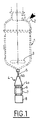
- the polymer is poured through the nozzle 4a and the die 4b by opening the bottom valve 5.
- the nozzle 4a and die 4b assembly constitutes the die block 4.
- the rods 6 leaving the die are cooled by a curtain of water 7 and fed into a granulator 8 which cuts the rods into granules a few millimeters in length.
- the granules are then dried and then stored in silos after possible sieving.
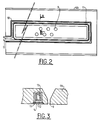
- the die 4b shown in FIGS. 2 and 3 is a metallic mass, for example a parallelepiped, comprising holes 9 in the die in which the rods 6 are formed.
- the outlet face of the die comprises a groove 10 in the vicinity of the die holes 9.
- An electromagnetic inductor 11 is disposed in this groove, advantageously closed by a plate 14.
- This inductor illustrated in FIG. 3, is coated with a layer 12 that is electrically insulating but advantageously a good conductor of heat. Furthermore, this insulating layer 12 will have to withstand the casting temperatures of the polymers, that is to say temperatures of the order of 250 ° C. to 400 ° C.
- Ceramic powders such as magnesia or boron nitride.
- the inductor 11 is disposed in the groove 10, the latter being filled with an insulator 12.
- the inductors 11 are devices comprising a solenoid which may be a single-coil inductor arranged around a magnetic element, allowing homogeneous heating of the die and mainly of the part of the die comprising the tap holes.
- This solenoid is advantageously a copper tube.
- a circulation 13 of cooling fluid is provided in the inductors. This circulation can be ensured by the use of a hollow copper inductor.
- the cooling fluid is advantageously either air or water, or any refrigerant fluids.
- the inductor 11 is connected to a generator (not shown) delivering an appropriate power and advantageously comprising a servo means which makes it possible to regulate the operation and the supply of the inductor by measuring the temperature of the die.
- This power supply is carried out with a frequency current any such as low frequencies, medium frequencies or high frequencies, depending on the geometry of the die to be heated.
- the example below illustrates the operation of a discontinuous polyester production installation equipped with a die heated by an electromagnetic inductor in accordance with the invention.
- the polymerization reactor 1 contains a charge of polymer under development, at a temperature of 285 ° C. Valve 5 is closed.
- the die 4b When the degree of polymerization is reached, the die 4b is heated to a temperature between 270 and 290 ° C. by supplying the inductor 11 with a frequency current at 500 Hz. This warming up takes place in a few seconds.
- the bottom valve 5 is open, the polymer can flow immediately through the holes 9 of the die, because the polymer which could be trapped in the holes has been made fluid and ejectable by the prior temperature setting of the die.
- the die at the end of casting the die is rapidly cooled to a cooling temperature defined above, for example 250 ° C.
- a cooling temperature defined above, for example 250 ° C. This cooling is obtained in the embodiment described by stopping the current supply to the inductor, but maintains the circulation of the cooling fluid.
- the polymer is fixed in the holes of the die and forms a tight plug.
- the temperature of the die is then maintained at a temperature above the crystallization temperature of the polymer, namely for polyethylene terephthalate, at a temperature above 200 ° C.
- a temperature above the crystallization temperature of the polymer namely for polyethylene terephthalate
- cooling to a too low temperature can cause the polymer to shrink or at least suppress the adhesion of the polymer to the surface of the die holes, the plug then no longer being tight.
- the polyester obtained has a constant quality during casting with an index of yellow varying slightly from one granule to another, the total index of the polymer cast (statistical measurement of the total casting ) having a value lower than that of a polymer obtained with casting in a die not heated by induction. This gain on the yellow index can be evaluated at several points.
- Another advantage of the process of the invention is the possibility of working at a die temperature higher than the temperature of the polymer in the reactor.
- the casting speed of the polymer is increased, decreasing the casting time.
- the degradation phenomena of the polymer in the reactor occurring especially at the end of casting are also reduced.
Landscapes
- Engineering & Computer Science (AREA)
- Mechanical Engineering (AREA)
- Physics & Mathematics (AREA)
- Thermal Sciences (AREA)
- Manufacturing & Machinery (AREA)
- Processing And Handling Of Plastics And Other Materials For Molding In General (AREA)
- Multicomponent Fibers (AREA)
- Polyesters Or Polycarbonates (AREA)
- Extrusion Moulding Of Plastics Or The Like (AREA)
Abstract
Description
- La présente invention concerne un procédé et un dispositif pour la fabrication de polymères.
- Elle concerne plus particulièrement un dispositif et un procédé d'extrusion des polymères sous forme de joncs, et plus particulièrement l'extrusion des polymères thermoplastiques.
- Les polymères thermoplastiques tels que les polyesters, polyamides sont généralement fabriqués dans des réacteurs fonctionnant en continu ou discontinu, la fin de réaction étant contrôlée par la viscosité du milieu réactionnel. En fin de réaction, les polymères sont coulés à travers une filière de coulée comprenant des trous de diamètre égal à quelques millimètres, pour former des joncs. Ces joncs sont généralement refroidis après la sortie de filière, par exemple par de l'eau, puis découpés pour former des granulés. Ces granulés sont utilisés comme matières premières par les industries de mise en forme telle que l'industrie textile ou de la fabrication de fils ou fibres, l'industrie de réalisation de compounds pour la fabrication de pièces moulées en matières plastiques.
- Les industries utilisatrices ou de transformation demandent une qualité élevée du polymère, et notamment une grande régularité de la qualité. En effet, si certains granulés présentent une qualité médiocre, telle que mauvais degré de polymérisation, degré de dégradation élevée, degré de cristallinité différent, ces irrégularités peuvent provoquer des casses lors de la fabrication de fils de titre fin ou des points de faiblesse mécanique dans les pièces moulées, ou les fils de plus gros titres tels que les monofilaments.
- Dans les procédés actuels, ces irrégularités interviennent principalement lors des phases de début et fin d'opération dans les procédés discontinus, ou à l'occasion d'anomalies de fonctionnement des procédés continus.
- Ainsi, à titre d'illustration, dans les procédés discontinus la filière de coulée et la vanne de fond du réacteur de polymérisation retiennent une certaine quantité de polymère en fin de coulée d'une opération. Ce polymère est en contact avec l'oxygène de l'air et subit donc une dégradation entre deux coulées. Lors de la coulée suivante, ce polymère dégradé devra être éjecté et rejeté par le flux du nouveau polymère.
- Ce rejet qui peut être de l'ordre de plusieurs kilogrammes représente une diminution de la rentabilité du procédé. En outre, il est impossible de contrôler et déterminer de manière précise quelle quantité de rejet devra être effectuée pour éviter toute pollution de la production.
- En outre, dans les procédés actuels, la température de la filière n'est pas contrôlée de manière uniforme, ce qui peut provoquer la présence de trous bouchés lors du début de la coulée, et des différences de propriétés entre les joncs.
- L'invention a notamment pour but de remédier à ces inconvénients, en proposant un procédé de fabrication d'un polymère thermoplastique permettant de contrôler la température de la filière de coulée pour améliorer la qualité et l'homogénéité du polymère produit et diminuer ou même supprimer les rejets de polymère en début et fin d'opération.
- A cet effet, l'invention propose un procédé de fabrication de polymères thermoplastiques consistant à réaliser la polymérisation jusqu'à un degré déterminé de polymérisation puis à couler le polymère fondu à travers les trous d'une filière de coulée pour former des fils ou joncs et récupérer ceux-ci pour, par exemple, produire des granulés par coupe des joncs. Ce procédé se caractérise en ce que la température de la filière de coulée, au moins au voisinage des trous de filière, est contrôlée et régulée par un ou des moyens de chauffage et/ou refroidissement disposés au voisinage des trous de filières.
- Ainsi, la filière pourra être portée en température avant le début d'une coulée de polymère pour limiter la formation de bouchons.
- En outre, la température de la filière étant homogène, tous les joncs de polymère extrudés subissent un refroidissement identique, produisant ainsi un polymère homogène, notamment sur le plan du degré de cristallinité et de la couleur.
- Selon une autre caractéristique de l'invention, la température de la filière est régulée par un chauffage par induction électromagnétique, les moyens de chauffage et/ou de refroidissement comprenant au moins un inducteur électromagnétique.
- Par ailleurs, le chauffage par induction électromagnétique peut permettre un chauffage très rapide voir instantané diminuant ainsi les problèmes d'inertie thermique de la filière. Ainsi, l'écoulement du polymère est amélioré car sa température est au moins maintenue à la température du réacteur de polycondensation.
- Un autre avantage important du chauffage par induction électromagnétique réside dans le fait qu'il permet de réguler la température de la filière. En effet, les inducteurs électromagnétiques comprennent un circuit de refroidissement, notamment un circuit de refroidissement par circulation d'eau ou d'air. En conséquence, ces inducteurs permettent de chauffer la filière mais également de la refroidir.
- Toutefois, selon le procédé de l'invention on peut prévoir un circuit indépendant de refroidissement de la filière, par exemple en prévoyant des conduits de circulation d'un fluide porteur de frigories sur ou dans la masse de la filière. Dans ce mode de réalisation, les moyens de refroidissement sont distincts des moyens de chauffage.
- Selon le procédé de l'invention, la température du polymère dans les trous de filière peut être contrôlée et maintenue homogène.
- En outre, avant le début de chaque opération la filière peut être chauffée très rapidement à une température voisine de la température de coulée du polymère pour ainsi permettre l'éjection rapide du polymère contenu dans les trous de filière et résidu de la coulée précédente.
- Dans un autre mode de réalisation du procédé de l'invention, après la fin de la coulée, la filière est refroidie à une température telle que le polymère est dans un état figé, c'est à dire ne s'écoule pas sous son propre poids, mais que sa surface reste adhésive à la paroi du trou de filière. Ainsi, le polymère fige dans les trous de filière pour former des bouchons étanches. Pour plus de clarté cette température sera appellée température de refroidissement.
- Les températures limites entre lesquelles doit se situer la température de refroidissement peuvent être illustrées, pour la limite supérieure par la température de ramollissement du polymère et pour la limite inférieure par la température de cristallisation de celui-ci.
- Ces bouchons étanches isolent le reste du polymère contenu dans la filière et dans le système vanne/buse de coulée du polymère disposé en fond du réacteur de polymérisation, d'une contamination par l'air.
- Ces bouchons améliorent l'étanchéité de la vanne de fond du réacteur qui présente souvent des fuites dues à l'usure provoquée par le pouvoir abrasif du polymère.
- Avant la coulée suivante, la filière est chauffée à une température voisine de la température de coulée, l'éjection des bouchons étant réalisée instantanément dès l'ouverture de la vanne de fond du réacteur de polymérisation.
- Cette première partie de polymère formant les bouchons doit être rejetée pour éviter la pollution du polymère total par le polymère constituant les bouchons qui a subi une dégradation par contact avec l'air. Toutefois, après quelques secondes de coulée, la production peut être récupérée car elle n'est pas polluée par les résidus de la coulée précédente. Ainsi, le polymère ayant résidé dans la filière et le système vanne/buse de coulée n'ayant subi aucune dégradation peut être incorporé à la production sans risque de pollution de celle-ci.
- De ce fait, les pertes de polymères en fin et au début de chaque coulée sont diminuées de plusieurs kilogrammes.
- L'invention a également pour objet une filière comprenant un dispositif de régulation de température comprenant au moins un inducteur électromagnétique.
- L'inducteur électromagnétique est avantageusement revêtu d'une couche isolante résistante à des températures élevées, par exemple nettement supérieures à la température de fusion des polymères thermoplastiques.
- Selon un mode de réalisation de l'invention, le ou les inducteurs électromagnétiques sont disposées au voisinage des extrémités débouchantes des trous de la filière, par exemple dans une rainure formée sur la face extérieure de sortie des joncs de la filière. En outre les inducteurs sont disposés de telle manière que les trous de la filière sont dans le champ électromagnétique généré par ceux-ci.
- Selon une autre caractéristique préférée, les inducteurs électromagnétiques comprennent un circuit de refroidissement, de préférence le fluide réfrigérant est l'eau.
- La puissance, la longueur ou le nombre des inducteurs sont déterminés en fonction de la filière à chauffer.
- Le procédé et le dispositif de l'invention peuvent s'appliquer à la fabrication de nombreux polymères, aussi bien dans les procédés continus que discontinus.
- Ce procédé s'applique notamment à la fabrication des polyesters tels que les polytéréphtalates d'éthylèneglycol, polytéréphtalates de butylèneglycol, copolyesters, les polyesters thermotropes etc..., de polyamides comme les polyamides 6.6, 6, 6.12, 6.10 etc ..., l'acétate de cellulose.
- Plus généralement le procédé s'applique aux fabrications de polymères dans lesquelles le polymère est coulée dans une filière en sortie de réacteur de polymérisation.
- D'autres buts, avantages et détails apparaîtront plus clairement au vu des exemples donnés uniquement à titre indicatif et de la description d'un dispositif faite en référence aux figures annexées représentant un mode de réalisation de l'invention et dans lesquelles :
- la figure 1 est un schéma synoptique d'un dispositif polymériseur/système de coulée d'une installation de production de polyester,
- la figure 2 est une vue schématique de la face inférieure d'un mode de réalisation d'une filière conforme à l'invention, et
- la figure 3 est une vue schématique en coupe avec agrandissement selon la ligne III - III de la figure 2.
- Les procédés de fabrication de polymères, notamment de polymères thermoplastiques sont généralement mis en oeuvre dans des installations comprenant des réacteurs agités dans lesquels est réalisée la polymérisation. Un exemple de réacteur 1, est illustré à la figure 1. Les monomères et autres additifs sont introduits dans le réacteur 1 par l'entrée 2. La masse réactionnelle est portée à la température de polymérisation, sous agitation. L'avancement de la polymérisation est déterminée par la mesure de l'évolution du couple des forces nécessaire pour entraîner l'agitateur 3. En effet, ce couple est fonction de la viscosité du mélange réactionnel.
- Quand le degré de polymérisation ou la viscosité désiré est atteint, le polymère est coulé à travers la buse 4a et la filière 4b par ouverture de la vanne de fond 5. L'ensemble buse 4a et filière 4b constitue le bloc filière 4.
- Les joncs 6 sortant de la filière sont refroidis par un rideau d'eau 7 et alimentés dans un granulateur 8 qui coupe les joncs en granulés de quelques millimètres de longueur. Les granulés sont ensuite séchés puis stockés dans des silos après un éventuel tamisage.
- Selon l'invention, la filière 4b représentée aux figures 2 et 3 est une masse métallique par exemple parallélépipédique comprenant des trous 9 de filière dans lesquels sont formés les joncs 6.
- Cette filière peut comprendre des plaques (non représentées) qui permettent d'obturer les trous de filières. Cette plaque est par exemple disposée sur la face d'entrée de la filière.
- Selon l'invention, la face de sortie de la filière comprend une gorge 10 au voisinage des trous de filière 9. Un inducteur électromagnétique 11 est disposé dans cette gorge, avantageusement obturée par une plaque 14.
- Cet inducteur, illustré à la figure 3, est revêtu d'une couche 12 isolante électriquement mais avantageusement bonne conductrice de la chaleur. Par ailleurs, cette couche 12 isolante devra résister aux températures de coulée des polymères, c'est-à-dire à des températures de l'ordre de 250°C à 400°C.
- Comme matière isolante, on peut citer les poudres céramiques telles que la magnésie ou le nitrure de bore.
- Selon un autre mode de réalisation, l'inducteur 11 est disposé dans la gorge 10, celle-ci étant rempli par un isolant 12.
- Les inducteurs 11 sont des dispositifs comprenant un solénoïde qui peut être un inducteur monospire disposé autour d'un élément magnétique, permettant un chauffage homogène de la filière et principalement de la partie de la filière comprenant les trous de coulée. Ce solénoïde est avantageusement un tube de cuivre.
- Dans le mode de réalisation préféré de l'invention, une circulation 13 de fluide de refroidissement est prévue dans les inducteurs. Cette circulation peut être assurée par l'utilisation d'inducteur en cuivre creux. Le fluide de refroidissement est avantageusement, soit de l'air soit de l'eau, soit tout fluides frigo-porteurs.
- L'inducteur 11 est connecté à un générateur (non représenté) délivrant une puissance appropriée et comprenant avantageusement un moyen d'asservissement qui permet de réguler le fonctionnement et l'alimentation de l'inducteur par mesure de la température de la filière. Cette alimentation est réalisée avec un courant de fréquences quelconques telles que basses fréquences, moyennes fréquences ou hautes fréquences, selon la géométrie de la filière à chauffer.
- L'exemple ci-dessous illustre le fonctionnement d'une installation discontinue de production de polyester équipée d'une filière chauffée par un inducteur électromagnétique conformément à l'invention.
- Le réacteur de polymérisation 1 contient une charge de polymère en cours d'élaboration, à une température de 285°C. La vanne 5 est fermée.
- Quand le degré de polymérisation est atteint, la filière 4b est chauffée à une température comprise entre 270 et 290°C par alimentation de l'inducteur 11 avec un courant de fréquences à 500 Hz. Cette mise en température s'effectue en quelques secondes. La vanne de fond 5 est ouverte, le polymère peut s'écouler immédiatement par les trous 9 de la filière, car le polymère qui pouvait être emprisonné dans les trous a été rendu fluide et éjectable par la mise en température préalable de la filière.
- En conséquence, seule la partie contenue dans la filière avant l'ouverture de la vanne de fond devra être éliminée, cette élimination étant réalisée immédiatement pour tous les trous de la filière. La température de la filière est maintenue homogène pendant la durée de la coulée.
- Selon un mode de réalisation de l'invention, en fin de coulée la filière est refroidie rapidement à une température de refroidissement définie ci-dessus, par exemple 250°C. Ce refroidissement est obtenu dans le mode de réalisation décrit par arrêt de l'alimentation en courant de l'inducteur, mais maintient de la circulation du fluide de refroidissement.
- Ainsi, le polymère est figé dans les trous de la filière et forme un bouchon étanche.
- La température de la filière est alors maintenue à une température supérieure à la température de cristallisation du polymère, à savoir pour le polyéthylène téréphtalate, à une température supérieure à 200°C. En effet, un refroidissement à une température trop basse peut provoquer une rétraction du polymère ou tout au moins supprimer l'adhérence du polymère à la surface des trous de filière, le bouchon n'étant alors plus étanche.
- Selon le procédé de l'invention, le polyester obtenu présente une qualité constante au cours de la coulée avec un indice de jaune variant faiblement d'un granulé à l'autre, l'indice total du polymère coulé (mesure statistique sur la coulée totale) ayant une valeur inférieure à celle d'un polymère obtenu avec coulée dans une filière non chauffée par induction. Ce gain sur l'indice de jaune peut être évalué à plusieurs points.
- Un autre avantage du procédé de l'invention est la possibilité de travailler à une température de filière plus élevée que la température du polymère dans le réacteur. Ainsi, la vitesse de coulée du polymère est augmentée, diminuant le temps de coulée. Les phénomènes de dégradation du polymère dans le réacteur intervenant surtout en fin de coulée sont également diminués.
Claims (12)
- Procédé de fabrication de polymères thermoplastiques comprenant les étapes suivantes :• polymérisation d'un polymère dans un réacteur de polymérisation jusqu'à un degré de polymérisation déterminé,• coulée du polymère dans une filière pour former des joncs ou des fils,• refroidissement des joncs ou fils en sortie de filière, et• récupération des joncs.caractérisé en ce que la température de la filière de coulée, au moins au voisinage des trous de filière, est contrôlée et régulée par un ou des moyens de chauffage et/ou refroidissement disposés au voisinage des trous de filières.
- Procédé selon la revendication 1, caractérisé en ce que la température de la filière est régulée par un chauffage par induction électromagnétique.
- Procédé selon l'une des revendications 1 ou 2, caractérisé en ce que le chauffage par induction électromagnétique est généré par au moins un inducteur disposé au voisinage des trous de filière.
- Procédé selon l'une des revendications précédentes, caractérisé en ce que les moyens de refroidissement sont distincts des moyens de chauffage.
- Procédé selon la revendication 3, caractérisé en ce que les moyens de refroidissement de la filière comprennent les moyens de refroidissement des inducteurs électromagnétiques.
- Procédé selon l'une des revendications précédentes, caractérisé en ce que, avant le début d'une coulée, la filière est portée à une température sensiblement égale à la température de coulée.
- Procédé selon l'une des revendications précédentes, caractérisé en ce que, en fin ou arrêt d'une coulée de polymère, la filière est refroidie à une température de refroidissement à laquelle le polymère est dans un état figé, c'est à dire ne s'écoule pas sous son propre poids, mais que sa surface reste adhésive au paroi du trou de filière.
- Filière de coulée de polymère thermoplastique caractérisée en ce qu'elle comprend des moyens de chauffage et de refroidissement pour réguler sa température.
- Filière selon la revendication 8, caractérisée en ce que les moyens de chauffage sont des inducteurs électromagnétiques.
- Filière selon la revendication 8 ou 9, caractérisée en ce que les moyens de refroidissement sont constitués par des canaux formés sur ou dans la filière pour assurer une circulation d'un fluide de refroidissement.
- Filière selon la revendication 8 ou 9, caractérisée en ce que les moyens de refroidissement de la filière sont constitués par les moyens de refroidissement du ou des inducteurs électromagnétiques.
- Filière selon l'une des revendications 9 à 11, caractérisée en ce que le ou les inducteurs électromagnétiques sont disposés dans une gorge formée sur la face de sortie de la filière, au voisinage des trous de filière.
Applications Claiming Priority (2)
| Application Number | Priority Date | Filing Date | Title |
|---|---|---|---|
| FR9408781A FR2722133B1 (fr) | 1994-07-08 | 1994-07-08 | Procede et dispositif de fabrication de polymeres |
| FR9408781 | 1994-07-08 |
Publications (2)
| Publication Number | Publication Date |
|---|---|
| EP0691192A1 true EP0691192A1 (fr) | 1996-01-10 |
| EP0691192B1 EP0691192B1 (fr) | 2000-03-22 |
Family
ID=9465418
Family Applications (1)
| Application Number | Title | Priority Date | Filing Date |
|---|---|---|---|
| EP95420192A Expired - Lifetime EP0691192B1 (fr) | 1994-07-08 | 1995-07-07 | Procédé et dispositif de fabrication de polymères |
Country Status (4)
| Country | Link |
|---|---|
| EP (1) | EP0691192B1 (fr) |
| AT (1) | ATE190903T1 (fr) |
| DE (1) | DE69515745D1 (fr) |
| FR (1) | FR2722133B1 (fr) |
Cited By (2)
| Publication number | Priority date | Publication date | Assignee | Title |
|---|---|---|---|---|
| EP0753392A1 (fr) * | 1995-07-13 | 1997-01-15 | RIETER AUTOMATIK GmbH | Dispositif de fermeture d'une masse fondue, notamment en matière plastique |
| EP0754536A1 (fr) * | 1995-07-18 | 1997-01-22 | RIETER AUTOMATIK GmbH | Dispositif de fermeture d'une masse fondue, notamment en matière plastique |
Citations (7)
| Publication number | Priority date | Publication date | Assignee | Title |
|---|---|---|---|---|
| US3521325A (en) * | 1967-02-15 | 1970-07-21 | Barmag Barmer Maschf | Inductively heated extrusion die |
| JPS5726420A (en) * | 1980-07-24 | 1982-02-12 | Fuji Electric Co Ltd | Cooling device for induction coil |
| JPS57167209A (en) * | 1981-04-07 | 1982-10-15 | Nippon Koshuha Kk | Quick formation of plastic film |
| JPS62177207A (ja) * | 1986-01-27 | 1987-08-04 | Toray Ind Inc | 溶融紡糸方法 |
| JPS63309408A (ja) * | 1987-06-12 | 1988-12-16 | Inoue Japax Res Inc | 加熱成形用型装置 |
| JPH02301505A (ja) * | 1989-05-16 | 1990-12-13 | Kawasaki Steel Corp | 金属溶解炉からの溶融金属排出制御方法 |
| JPH0544105A (ja) * | 1991-02-18 | 1993-02-23 | Toray Ind Inc | 溶融紡糸方法 |
-
1994
- 1994-07-08 FR FR9408781A patent/FR2722133B1/fr not_active Expired - Fee Related
-
1995
- 1995-07-07 EP EP95420192A patent/EP0691192B1/fr not_active Expired - Lifetime
- 1995-07-07 AT AT95420192T patent/ATE190903T1/de not_active IP Right Cessation
- 1995-07-07 DE DE69515745T patent/DE69515745D1/de not_active Expired - Lifetime
Patent Citations (7)
| Publication number | Priority date | Publication date | Assignee | Title |
|---|---|---|---|---|
| US3521325A (en) * | 1967-02-15 | 1970-07-21 | Barmag Barmer Maschf | Inductively heated extrusion die |
| JPS5726420A (en) * | 1980-07-24 | 1982-02-12 | Fuji Electric Co Ltd | Cooling device for induction coil |
| JPS57167209A (en) * | 1981-04-07 | 1982-10-15 | Nippon Koshuha Kk | Quick formation of plastic film |
| JPS62177207A (ja) * | 1986-01-27 | 1987-08-04 | Toray Ind Inc | 溶融紡糸方法 |
| JPS63309408A (ja) * | 1987-06-12 | 1988-12-16 | Inoue Japax Res Inc | 加熱成形用型装置 |
| JPH02301505A (ja) * | 1989-05-16 | 1990-12-13 | Kawasaki Steel Corp | 金属溶解炉からの溶融金属排出制御方法 |
| JPH0544105A (ja) * | 1991-02-18 | 1993-02-23 | Toray Ind Inc | 溶融紡糸方法 |
Non-Patent Citations (6)
| Title |
|---|
| DATABASE WPI Week 8212, Derwent World Patents Index; AN 82-D2150E * |
| DATABASE WPI Week 8905, Derwent World Patents Index; AN 89-036031 * |
| DATABASE WPI Week 9105, Derwent World Patents Index; AN 91-032472 * |
| PATENT ABSTRACTS OF JAPAN vol. 12, no. 28 (C - 471) 27 January 1988 (1988-01-27) * |
| PATENT ABSTRACTS OF JAPAN vol. 17, no. 349 (C - 1078) 2 July 1993 (1993-07-02) * |
| PATENT ABSTRACTS OF JAPAN vol. 7, no. 9 (M - 185) 14 January 1983 (1983-01-14) * |
Cited By (2)
| Publication number | Priority date | Publication date | Assignee | Title |
|---|---|---|---|---|
| EP0753392A1 (fr) * | 1995-07-13 | 1997-01-15 | RIETER AUTOMATIK GmbH | Dispositif de fermeture d'une masse fondue, notamment en matière plastique |
| EP0754536A1 (fr) * | 1995-07-18 | 1997-01-22 | RIETER AUTOMATIK GmbH | Dispositif de fermeture d'une masse fondue, notamment en matière plastique |
Also Published As
| Publication number | Publication date |
|---|---|
| EP0691192B1 (fr) | 2000-03-22 |
| DE69515745D1 (de) | 2000-04-27 |
| FR2722133B1 (fr) | 1996-08-23 |
| FR2722133A1 (fr) | 1996-01-12 |
| ATE190903T1 (de) | 2000-04-15 |
Similar Documents
| Publication | Publication Date | Title |
|---|---|---|
| CN101448614B (zh) | 蜡和似蜡材料造粒的装置和方法 | |
| JP5253735B2 (ja) | ポリマーの水中ペレット化のためのプロセスおよび装置 | |
| JP4085419B2 (ja) | プラスチック押し出し材を供給し処理する方法及び装置 | |
| EP0691192B1 (fr) | Procédé et dispositif de fabrication de polymères | |
| Oliveira et al. | Structure-properties relationships in rotationally moulded polyethylene | |
| CA1303356C (fr) | Procede et dispositif de fabrication de fibres en matieres thermoplastiques en particulier de fibres de verre | |
| WO1987007546A1 (fr) | Procede et dispositif de granulation d'un materiau fondu | |
| FR2711034A1 (fr) | Appareil de lévitation et de fusion et son procédé de fonctionnement. | |
| CA2223508A1 (fr) | Dispositif et procede d'alimentation pour extrudeuses | |
| FR2760384A1 (fr) | Procede et appareil pour la production de granules | |
| FR2623744A1 (fr) | Procede de fabrication d'une pellicule thermoplastique thermore tractable par etirages successifs | |
| EP0586481B1 (fr) | Procede et dispositif pour obtenir un fil en alliage metallique amorphe a base de fer | |
| CA2018205C (fr) | Dispositif pour recuperer par fusion le metal constitutif d'un noyau fusible | |
| EP1103361B1 (fr) | Ligne de fabrication de câble électrique avec récupération de rebuts de matière thermoplastique, et procédé de récupération associé | |
| FR2565887A1 (fr) | Ligne de vulcanisation et/ou reticulation continue, notamment pour la realisation de couches synthetiques isolantes sur des cables | |
| CA2251007C (fr) | Procede de coulee continue des metaux et installation de coulee pour sa mise oeuvre | |
| EP0290423B1 (fr) | Dispositif de fabrication en continu d'une bande métallique mince | |
| FR2927910A1 (fr) | Procede de cristallogenese d'un materiau electriquement conducteur a l'etat fondu. | |
| EP0240482B1 (fr) | Dispositif pour la coulée de l'acier | |
| CA2204548C (fr) | Systeme a levres de filieres chauffees | |
| FR2514688A1 (fr) | Materiau compose de fibres de carbone et d'une matiere thermoplastique, procede de preparation et application dudit materiau | |
| JPH0224886B2 (fr) | ||
| BE390381A (fr) | ||
| FR2459122A1 (fr) | Procede et dispositif pour la fabrication de profiles en matiere plastique expansee en mousse | |
| LU88522A1 (fr) | Procèdé et installation pour le recyclage d'objets composés d'un polymère thermoplastique |
Legal Events
| Date | Code | Title | Description |
|---|---|---|---|
| PUAI | Public reference made under article 153(3) epc to a published international application that has entered the european phase |
Free format text: ORIGINAL CODE: 0009012 |
|
| AK | Designated contracting states |
Kind code of ref document: A1 Designated state(s): AT BE CH DE ES GB GR IE IT LI LU NL PT |
|
| K1C1 | Correction of patent application (title page) published |
Effective date: 19960110 |
|
| 17P | Request for examination filed |
Effective date: 19960607 |
|
| RAP1 | Party data changed (applicant data changed or rights of an application transferred) |
Owner name: RHODIA CHIMIE |
|
| 17Q | First examination report despatched |
Effective date: 19980602 |
|
| GRAG | Despatch of communication of intention to grant |
Free format text: ORIGINAL CODE: EPIDOS AGRA |
|
| GRAG | Despatch of communication of intention to grant |
Free format text: ORIGINAL CODE: EPIDOS AGRA |
|
| GRAH | Despatch of communication of intention to grant a patent |
Free format text: ORIGINAL CODE: EPIDOS IGRA |
|
| GRAH | Despatch of communication of intention to grant a patent |
Free format text: ORIGINAL CODE: EPIDOS IGRA |
|
| GRAA | (expected) grant |
Free format text: ORIGINAL CODE: 0009210 |
|
| AK | Designated contracting states |
Kind code of ref document: B1 Designated state(s): AT BE CH DE ES GB GR IE IT LI LU NL PT |
|
| PG25 | Lapsed in a contracting state [announced via postgrant information from national office to epo] |
Ref country code: NL Free format text: LAPSE BECAUSE OF FAILURE TO SUBMIT A TRANSLATION OF THE DESCRIPTION OR TO PAY THE FEE WITHIN THE PRESCRIBED TIME-LIMIT Effective date: 20000322 Ref country code: IT Free format text: LAPSE BECAUSE OF FAILURE TO SUBMIT A TRANSLATION OF THE DESCRIPTION OR TO PAY THE FEE WITHIN THE PRE;WARNING: LAPSES OF ITALIAN PATENTS WITH EFFECTIVE DATE BEFORE 2007 MAY HAVE OCCURRED AT ANY TIME BEFORE 2007. THE CORRECT EFFECTIVE DATE MAY BE DIFFERENT FROM THE ONE RECORDED.SCRIBED TIME-LIMIT Effective date: 20000322 Ref country code: GR Free format text: LAPSE BECAUSE OF NON-PAYMENT OF DUE FEES Effective date: 20000322 Ref country code: GB Free format text: LAPSE BECAUSE OF FAILURE TO SUBMIT A TRANSLATION OF THE DESCRIPTION OR TO PAY THE FEE WITHIN THE PRESCRIBED TIME-LIMIT Effective date: 20000322 Ref country code: ES Free format text: THE PATENT HAS BEEN ANNULLED BY A DECISION OF A NATIONAL AUTHORITY Effective date: 20000322 Ref country code: AT Free format text: LAPSE BECAUSE OF FAILURE TO SUBMIT A TRANSLATION OF THE DESCRIPTION OR TO PAY THE FEE WITHIN THE PRESCRIBED TIME-LIMIT Effective date: 20000322 |
|
| REF | Corresponds to: |
Ref document number: 190903 Country of ref document: AT Date of ref document: 20000415 Kind code of ref document: T |
|
| REG | Reference to a national code |
Ref country code: CH Ref legal event code: EP |
|
| REF | Corresponds to: |
Ref document number: 69515745 Country of ref document: DE Date of ref document: 20000427 |
|
| REG | Reference to a national code |
Ref country code: IE Ref legal event code: FG4D Free format text: FRENCH |
|
| PG25 | Lapsed in a contracting state [announced via postgrant information from national office to epo] |
Ref country code: PT Free format text: LAPSE BECAUSE OF FAILURE TO SUBMIT A TRANSLATION OF THE DESCRIPTION OR TO PAY THE FEE WITHIN THE PRESCRIBED TIME-LIMIT Effective date: 20000623 |
|
| PG25 | Lapsed in a contracting state [announced via postgrant information from national office to epo] |
Ref country code: DE Free format text: LAPSE BECAUSE OF FAILURE TO SUBMIT A TRANSLATION OF THE DESCRIPTION OR TO PAY THE FEE WITHIN THE PRESCRIBED TIME-LIMIT Effective date: 20000624 |
|
| PG25 | Lapsed in a contracting state [announced via postgrant information from national office to epo] |
Ref country code: LU Free format text: LAPSE BECAUSE OF NON-PAYMENT OF DUE FEES Effective date: 20000707 |
|
| PG25 | Lapsed in a contracting state [announced via postgrant information from national office to epo] |
Ref country code: LI Free format text: LAPSE BECAUSE OF NON-PAYMENT OF DUE FEES Effective date: 20000731 Ref country code: CH Free format text: LAPSE BECAUSE OF NON-PAYMENT OF DUE FEES Effective date: 20000731 Ref country code: BE Free format text: LAPSE BECAUSE OF NON-PAYMENT OF DUE FEES Effective date: 20000731 |
|
| NLV1 | Nl: lapsed or annulled due to failure to fulfill the requirements of art. 29p and 29m of the patents act | ||
| GBV | Gb: ep patent (uk) treated as always having been void in accordance with gb section 77(7)/1977 [no translation filed] |
Effective date: 20000322 |
|
| PLBQ | Unpublished change to opponent data |
Free format text: ORIGINAL CODE: EPIDOS OPPO |
|
| PLBI | Opposition filed |
Free format text: ORIGINAL CODE: 0009260 |
|
| PLBF | Reply of patent proprietor to notice(s) of opposition |
Free format text: ORIGINAL CODE: EPIDOS OBSO |
|
| BERE | Be: lapsed |
Owner name: RHODIA CHIMIE Effective date: 20000731 |
|
| 26 | Opposition filed |
Opponent name: BASF AKTIENGESELLSCHAFT Effective date: 20001222 |
|
| REG | Reference to a national code |
Ref country code: IE Ref legal event code: FD4D |
|
| REG | Reference to a national code |
Ref country code: CH Ref legal event code: PL |
|
| PLBF | Reply of patent proprietor to notice(s) of opposition |
Free format text: ORIGINAL CODE: EPIDOS OBSO |
|
| PLBD | Termination of opposition procedure: decision despatched |
Free format text: ORIGINAL CODE: EPIDOSNOPC1 |
|
| PLBM | Termination of opposition procedure: date of legal effect published |
Free format text: ORIGINAL CODE: 0009276 |
|
| STAA | Information on the status of an ep patent application or granted ep patent |
Free format text: STATUS: OPPOSITION PROCEDURE CLOSED |
|
| 27C | Opposition proceedings terminated |
Effective date: 20061022 |
|
| PLAB | Opposition data, opponent's data or that of the opponent's representative modified |
Free format text: ORIGINAL CODE: 0009299OPPO |