EP0692811A1 - Tube image couleur - Google Patents
Tube image couleur Download PDFInfo
- Publication number
- EP0692811A1 EP0692811A1 EP95304767A EP95304767A EP0692811A1 EP 0692811 A1 EP0692811 A1 EP 0692811A1 EP 95304767 A EP95304767 A EP 95304767A EP 95304767 A EP95304767 A EP 95304767A EP 0692811 A1 EP0692811 A1 EP 0692811A1
- Authority
- EP
- European Patent Office
- Prior art keywords
- electrode
- convergence
- supplementary
- cylinder
- final accelerating
- Prior art date
- Legal status (The legal status is an assumption and is not a legal conclusion. Google has not performed a legal analysis and makes no representation as to the accuracy of the status listed.)
- Granted
Links
- 230000005684 electric field Effects 0.000 description 23
- 239000011521 glass Substances 0.000 description 7
- 230000004075 alteration Effects 0.000 description 6
- 238000010894 electron beam technology Methods 0.000 description 6
- 238000009826 distribution Methods 0.000 description 5
- OAICVXFJPJFONN-UHFFFAOYSA-N Phosphorus Chemical compound [P] OAICVXFJPJFONN-UHFFFAOYSA-N 0.000 description 4
- 230000004323 axial length Effects 0.000 description 3
- 238000010586 diagram Methods 0.000 description 3
- 230000000694 effects Effects 0.000 description 2
- 230000009545 invasion Effects 0.000 description 2
- 230000035945 sensitivity Effects 0.000 description 1
Images


Classifications
-
- H—ELECTRICITY
- H01—ELECTRIC ELEMENTS
- H01J—ELECTRIC DISCHARGE TUBES OR DISCHARGE LAMPS
- H01J29/00—Details of cathode-ray tubes or of electron-beam tubes of the types covered by group H01J31/00
- H01J29/46—Arrangements of electrodes and associated parts for generating or controlling the ray or beam, e.g. electron-optical arrangement
- H01J29/48—Electron guns
- H01J29/50—Electron guns two or more guns in a single vacuum space, e.g. for plural-ray tube
- H01J29/503—Three or more guns, the axes of which lay in a common plane
Definitions
- This invention relates to a color-picture tube, in particular, to the structure of the electrodes, having high resolution all over the phosphor screen.
- the resolution of a color-picture tube depends much on the shape and size of the beam spot produced on the phosphor screen.
- the electrodes of the tube must have such a structure as to produce beam spots which are really circular and of small diameter.
- the section of the electron beam which passes through the main-lens electric-field of the electron gun becomes larger and the beam spot becomes non-circular due to the spherical aberration of the main-lens electric field.
- the aperture has been made as large as possible.
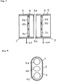
- a color-picture tube of the prior art as disclosed in the patent gazettes of Japanese patent application Toku-Ko-Hei 2-18540 or Toku-Kai-Hei 4-133247, as shown in Fig. 7 and Fig. 8, comprises the main lens part consisting of a convergence electrode 1 and an accelerating electrode 2.
- the convergence electrode 1 comprises a cylinder 3 with an elliptical section and an end plate 4 of the elliptical shape closing the cylinder 3 at the opening side 3a thereof.
- the end plate 4 is placed at a position a little backward from the opening 3a, and has three holes 4a, 4b, and 4c for electron passage arranged in-line.
- the accelerating electrode 2 comprises a cylinder 5 with an elliptical section and an end plate 6 of the elliptic shape closing the cylinder 5 at the opening side 5a thereof.
- the end plate 6 is placed at a position somewhat backward from the opening 5a, and has three holes 6a, 6b, and 6c for electron passage arranged in-line.
- three main-lens electric fields are formed between the three electron-beam-holes 4a, 4b, and 4c and the three electron-beam-holes 6a, 6b, and 6c, and the neibouring two of the three main-lens electric fields partially overlap, to form a main-lens electric field with large apertures.
- the undesirable effect of the spherical aberration can be offset, and the lens magnification may be reduced to produce circular small beam-spots on the phosphor screen.
- the conventional structure of the electrodes despite of its advantage to make the aperture of the main-lens electric-field large, naturally has a limitation. If the outer diameters of the convergence electrode and the final accelerating electrode are set to values near the inside diameter of the neck of the glass bulb, the wall electric-field of the neck part intrudes into the main-lens electric field. Also, if the diameter of the neck part becomes large, the deflection sensitivity is lowered.
- a color-picture tube comprises a convergence electrode, to which the focusing voltage is applied, a final accelerating electrode, to which the anode voltage is applied, and at least one supplementary electrode placed between the convergence electrode and the final accelerating electrode, to which a voltage higher than the focusing voltage and lower than the anode voltage is applied, wherein each of said convergence electrode and said final accelerating electrode comprises a cylinder of an ellipticalsection closed with an end plate of the elliptical section having three holes for electron passage arranged in-line, and at least one of said end plates is set at a position backward from the opening of said cylinder of said supplementary electrode side, andsaid supplementary electrode comprises a cylinder of an ellipticalsection arranged coaxially with said convergence electrode and final accelerating electrode.
- Another color-picture tube have a convergence electrode, to which the focusing voltage is applied, a final accelerating electrode, to which the anode voltage is applied, and at least one supplementary electrode of free electric potential (not connected to any power source) placed betweee convergence electrode and the final accelerating electrode, wherein each of said convergence electrode and said final accelerating electrode comprises a cylinder of an elliptical section closed with an end plate of the elliptical section having three holes for electron passage arranged in-line, and at least one of said end plates is set at a position backward from the opening of said cylinder of said supplementary electrode side, and said supplementary electrode comprises a cylinder of an elliptical section arranged coaxially with said convergence electrode and final accelerating electrode.
- the domain of the main-lens electric field which is formed between the end plates of said two electrodes are expanded.
- the supplementary electrode is supplied with a voltage higher than the focusing voltage and lower than the anode voltage, the electric potential distribution along the axis in the main-lens electric field domain becomes a gentle slope, and the spherical aberration of the main-lens electric field may be reduced further. Further, undesirable invasion of the wall electric-field of the neck of the glass bulb into the main-lens electric field can be prevented by the shield action of the supplementary electrode.
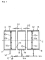
- Fig. 1 is a side sectional view of the main-lens part of a color-picture tube embodying the present invention.
- Fig. 2 is a front view of the main-lens part of a color-picture tube embodying the present invention.
- Fig. 3 is a side sectional view of the main part of a color-picture tube embodying the present invention.
- Fig.4 is a characteristic diagram showing the relationship between the main-lens aperture and the axial length of the supplementary electrode.
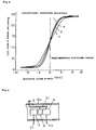
- Fig. 5 is a characteristic diagram illustrating the electric potential distribution along the axis of the main-lens part.
- Fig. 6 is a schematic diagram showing an energizing means to the supplementary electrode.
- Fig. 7 is a side sectional view of the main-lens part of a color-picture tube of the prior art.
- Fig. 8 is a front view of the main-lens part of a color-picture tube of the prior art.
- the main lens part of the color-picture tube comprises a convergence electrode 7, a final accelerating electrode 8, and a supplemantary electrode 9 in between, the convergence electrode 7 being given the focusing voltage Vf, the final accelerating electrode 8 being supplied with anode voltage Va.
- the supplementary electrode 9 is arranged coaxially with the convergence electrode 7 and the final accelerating electrode 8 and is given voltage Vm which is higher than the focusing voltage Vf and is lower than the anode voltage Va.
- the convergence electrode 7 comprises a cylinder 11 of an elliptic section closed with an end plate 10 of the elliptic shape, which is placed at a position a little backward from the opening 11a of the cylinder 11 and has three holes 10a, 10b, and 10c for electron beam passage arranged in-line as shown in Fig. 2(a).
- the final accelerating electrode 8, likewise as the con vergence electrode 7, comprises a cylinder 13 of an elliptic section closed with an end plate 12 of the elliptic shape, which is placed at a position a little backward from the opening 13a of the cylinder 11 and has three holes 12a, 12b, and 12c for electron beam passage arranged in-line.
- the supplementary electrode 9 comprises a cylinder 14 of an elliptic shape but has no end plate as show in Fig. 2(b).
- the main lens part comprising the convergence electrode 7, final accelerating electrode 8 and the supplementary electrode 9, together with three cathodes 15, three control electrodes 16, and an accelerating electrode 17 all arranged in-line, forms the electron gun, and the gun is enclosed within the neck 18a of a glass bulb 18 which is the envelope of the color-picture tube.
- the color-picture tube 18 has a funnel 18b, and is provided at the outside of the funnel 18b near the neck 18a with a deflection yoke 19 to generate deflection magnetic field, by which the three electron beams 20 emitted from the electron guns are deflected to fall on the fluorescent screen (not shown in the figure).
- the distance between the convergence electrode 7 and the final accelerating electrode 8 is larger compared to that of the conventional structure of electrode and the supplementary electrode 9 between them is provided with an arbitrary voltage higher than the focus voltage Vf but lower than the anode voltage Va, so that the electric potential gradient along the z-axis between the convergence electrode 7 and the final accelerating electrode 8 is more gentle than that of the conventional electrode. Consequently, the effective opening of the main-lens electric field becomes larger, and both the spherical aberration and the lens magnification are allowed to be lowered. Also, since the wall electric-field and the main-lens electric field are shielded by the supplementary electrode 9, the unfavorable effect of the wall electric-field on the way of the electron beam etc. can be prevented.
- Fig.4 shown is the variation of the effective main-lens opening against the variation of the axial length L of the supplementary electrode, for the axial length L thereof 0.6mm, 2mm, and 4mm, while the inner diameter of the glass bulb neck 18a being set 17.5mm, the distance G1 between the convergence electrode 7 and the supplementary electrode 9, 0.8mm, the distance G2 between the supplementary electrode 9 and the final accelerating electrode 8, 0.8mm, and Va, Vm, and Vf being set 25kV, 16kV, and 7kV respectively. Any of them shows larger value than the effective main-lens aperture (5.5mm ⁇ ) of the prior art electrodes.
- the potential gradient becomes gentle as L becomes larger, resulting in the enlarging of the effective main-lens-opening.
- the supplementary electrode 9 is a cylinder 14 which has no end plate, resulting in the enlargement of the lens-electric-field-forming domain common to the three main-lens electric fields.
- the potential distribution along the axis is of more gentle gradient than that of the conventional one and the effective main-lens opening can be enlarged.
- the invasion of the wall electric-field on the neck 18a of the glass bulb 18 into the main-lens electric field domain is prevented by the. shielding by the supplementary electrode 9.
- the supplementary electrode 9 is provided with a resistor 21 which is a means to apply to the supplementary electrode a voltage Vm higher than the focus voltageVf and lower than the anode voltage Va.
- the resistor 21 is connected with the power source of the anode voltage Va, and the other end with the ground E, and the voltage Vm is obtained from its middle tap.
- the resistor 21 may be formed as a film on a glass rod which supports the electron gun electrodes or as a film on the inside wall of the neck 18a of the bulb 18; the resistor 21 may not be linear form, but may be meandering or spiral.
- the supplementary electrode 9 may not be connected with the power source, but kept free.
- the supplementary electrode 9, which is placed between the convergence electrode 7 with focusing voltage Vf and the accelerating electrode 8 with anode voltage Va, is given a free voltage induced by both the electrodes 7 and 8.
- the supplementary electrode 9 may be constructed from several cylinders. Also, whereas, in the above embodiment, the end plate 10 of the convergence electrode 7 and the end plate 12 of the final accelerating electrode 8 were both placed at the positions both backward from the openings 11a and 13a of the cylinder 11 and 13, only one of the end plates may be placed at a backward position.
- the three holes for electron passage arranged in-line in the end plates 10 and 12 are not confined to be circular as shown in the figures, but may be all elliptic or of the similar shape, or the outside two holes may be circular or like.
- three main-lens electric fields are formed so as to have overlapping part between the adjacent ones and the supplementary electrode placed between the convergence electrode and the final accelerating electrode causes the electric potential distribution along the axis of the main-lens to have a moderate slope.
- the effective opening of the main-lens is enlarged and the spherical aberration and the lens magnification are both reduced, so that, the radius of the beam spot can be made smaller, realizing high preciseness over the phosphor screen.
Landscapes
- Cathode-Ray Tubes And Fluorescent Screens For Display (AREA)
- Eyeglasses (AREA)
Applications Claiming Priority (2)
| Application Number | Priority Date | Filing Date | Title |
|---|---|---|---|
| JP157749/94 | 1994-07-11 | ||
| JP15774994A JP3324282B2 (ja) | 1994-07-11 | 1994-07-11 | カラー受像管装置 |
Publications (2)
| Publication Number | Publication Date |
|---|---|
| EP0692811A1 true EP0692811A1 (fr) | 1996-01-17 |
| EP0692811B1 EP0692811B1 (fr) | 1998-09-16 |
Family
ID=15656513
Family Applications (1)
| Application Number | Title | Priority Date | Filing Date |
|---|---|---|---|
| EP95304767A Expired - Lifetime EP0692811B1 (fr) | 1994-07-11 | 1995-07-07 | Tube image couleur |
Country Status (8)
| Country | Link |
|---|---|
| US (1) | US5675211A (fr) |
| EP (1) | EP0692811B1 (fr) |
| JP (1) | JP3324282B2 (fr) |
| KR (1) | KR0173724B1 (fr) |
| CN (1) | CN1111895C (fr) |
| DE (1) | DE69504778T2 (fr) |
| MY (1) | MY112156A (fr) |
| TW (1) | TW321778B (fr) |
Cited By (1)
| Publication number | Priority date | Publication date | Assignee | Title |
|---|---|---|---|---|
| EP0798759A3 (fr) * | 1996-03-26 | 1999-06-16 | Sony Corporation | Tube à rayons cathodiques couleur |
Families Citing this family (12)
| Publication number | Priority date | Publication date | Assignee | Title |
|---|---|---|---|---|
| US6133685A (en) * | 1996-07-05 | 2000-10-17 | Matsushita Electronics Corporation | Cathode-ray tube |
| US6320333B1 (en) | 1997-02-07 | 2001-11-20 | Matsushita Electric Industrial Co., Ltd. | Color picture tube |
| JPH10255682A (ja) * | 1997-03-14 | 1998-09-25 | Sony Corp | 陰極線管 |
| US5907217A (en) * | 1997-07-09 | 1999-05-25 | Zenith Electronics Corporation | Uni-bipotential symmetrical beam in-line electron gun |
| JP3528526B2 (ja) | 1997-08-04 | 2004-05-17 | 松下電器産業株式会社 | カラー受像管装置 |
| JPH1167121A (ja) | 1997-08-27 | 1999-03-09 | Matsushita Electron Corp | 陰極線管 |
| KR100335012B1 (ko) * | 1999-11-20 | 2002-05-03 | 박권수 | 폐타이어용 열분해 반응장치 |
| KR20010047512A (ko) * | 1999-11-20 | 2001-06-15 | 권희덕 | 폐타이어용 열분해 반응장치 |
| JP3926953B2 (ja) | 1999-11-25 | 2007-06-06 | 株式会社東芝 | カラー受像管 |
| JP3975764B2 (ja) * | 2002-02-01 | 2007-09-12 | 松下電器産業株式会社 | 電子銃及びカラー受像管装置 |
| US6965192B2 (en) | 2002-03-20 | 2005-11-15 | Matsushita Electric Industrial Co., Ltd. | Color picture tube apparatus |
| JP2005310497A (ja) | 2004-04-20 | 2005-11-04 | Matsushita Toshiba Picture Display Co Ltd | カラーブラウン管装置 |
Citations (6)
| Publication number | Priority date | Publication date | Assignee | Title |
|---|---|---|---|---|
| JPS569946A (en) * | 1979-07-03 | 1981-01-31 | Mitsubishi Electric Corp | Electron gun |
| EP0226145A2 (fr) * | 1985-12-09 | 1987-06-24 | Kabushiki Kaisha Toshiba | Canon à électrons |
| EP0315269A1 (fr) * | 1987-11-04 | 1989-05-10 | Koninklijke Philips Electronics N.V. | Tube image en couleurs, système de déviation et canon électronique |
| JPH0218540A (ja) | 1988-07-06 | 1990-01-22 | Matsushita Electric Ind Co Ltd | 透過式背面スクリーン |
| JPH04133247A (ja) | 1990-09-25 | 1992-05-07 | Matsushita Electron Corp | カラー受像管用電子銃 |
| DE4336532A1 (de) * | 1992-12-17 | 1994-06-23 | Samsung Display Devices Co Ltd | Elektronenkanone mit dynamischer Fokussierung |
Family Cites Families (7)
| Publication number | Priority date | Publication date | Assignee | Title |
|---|---|---|---|---|
| JPS58103752A (ja) * | 1981-12-16 | 1983-06-20 | Hitachi Ltd | カラ−受像管用電子銃 |
| EP0152933B1 (fr) * | 1984-02-20 | 1988-03-02 | Kabushiki Kaisha Toshiba | Canon à électrons |
| US4922166A (en) * | 1986-06-30 | 1990-05-01 | Sony Corporation | Electron gun for multigun cathode ray tube |
| KR970011874B1 (en) * | 1989-07-31 | 1997-07-18 | Lg Electronics Inc | Electron gun for color picture tube |
| US4990822A (en) * | 1989-12-29 | 1991-02-05 | Zenith Electronics Corporation | Focusing electrode assembly for a color cathode ray tube electron gun |
| GB9104649D0 (en) * | 1991-03-05 | 1991-04-17 | Secr Defence | Focusing means for cathode ray tubes |
| US5394054A (en) * | 1993-07-19 | 1995-02-28 | Chunghwa Picture Tubes, Ltd. | Electron gun with electrostatic shielding and method of assembly therefor |
-
1994
- 1994-07-11 JP JP15774994A patent/JP3324282B2/ja not_active Expired - Fee Related
-
1995
- 1995-05-17 TW TW084104881A patent/TW321778B/zh active
- 1995-07-04 CN CN95109010A patent/CN1111895C/zh not_active Expired - Fee Related
- 1995-07-07 DE DE69504778T patent/DE69504778T2/de not_active Expired - Fee Related
- 1995-07-07 EP EP95304767A patent/EP0692811B1/fr not_active Expired - Lifetime
- 1995-07-10 MY MYPI95001922A patent/MY112156A/en unknown
- 1995-07-11 US US08/500,576 patent/US5675211A/en not_active Expired - Lifetime
- 1995-07-11 KR KR1019950020249A patent/KR0173724B1/ko not_active Expired - Fee Related
Patent Citations (6)
| Publication number | Priority date | Publication date | Assignee | Title |
|---|---|---|---|---|
| JPS569946A (en) * | 1979-07-03 | 1981-01-31 | Mitsubishi Electric Corp | Electron gun |
| EP0226145A2 (fr) * | 1985-12-09 | 1987-06-24 | Kabushiki Kaisha Toshiba | Canon à électrons |
| EP0315269A1 (fr) * | 1987-11-04 | 1989-05-10 | Koninklijke Philips Electronics N.V. | Tube image en couleurs, système de déviation et canon électronique |
| JPH0218540A (ja) | 1988-07-06 | 1990-01-22 | Matsushita Electric Ind Co Ltd | 透過式背面スクリーン |
| JPH04133247A (ja) | 1990-09-25 | 1992-05-07 | Matsushita Electron Corp | カラー受像管用電子銃 |
| DE4336532A1 (de) * | 1992-12-17 | 1994-06-23 | Samsung Display Devices Co Ltd | Elektronenkanone mit dynamischer Fokussierung |
Non-Patent Citations (2)
| Title |
|---|
| PATENT ABSTRACTS OF JAPAN vol. 005, no. 059 (E - 053) 22 April 1981 (1981-04-22) * |
| PATENT ABSTRACTS OF JAPAN vol. 016, no. 401 (E - 1253) 25 August 1992 (1992-08-25) * |
Cited By (4)
| Publication number | Priority date | Publication date | Assignee | Title |
|---|---|---|---|---|
| EP0798759A3 (fr) * | 1996-03-26 | 1999-06-16 | Sony Corporation | Tube à rayons cathodiques couleur |
| US6016030A (en) * | 1996-03-26 | 2000-01-18 | Sony Corporation | Color cathode-ray tube with intermediate electrode |
| US6100630A (en) * | 1996-03-26 | 2000-08-08 | Sony Corporation | Color cathode-ray tube |
| EP1365435A3 (fr) * | 1996-03-26 | 2007-08-22 | Sony Corporation | Tube à rayons cathodiques couleur |
Also Published As
| Publication number | Publication date |
|---|---|
| DE69504778T2 (de) | 1999-02-04 |
| TW321778B (fr) | 1997-12-01 |
| US5675211A (en) | 1997-10-07 |
| DE69504778D1 (de) | 1998-10-22 |
| EP0692811B1 (fr) | 1998-09-16 |
| CN1120730A (zh) | 1996-04-17 |
| JPH0822780A (ja) | 1996-01-23 |
| JP3324282B2 (ja) | 2002-09-17 |
| MY112156A (en) | 2001-04-30 |
| KR0173724B1 (ko) | 1999-02-01 |
| KR960005710A (ko) | 1996-02-23 |
| CN1111895C (zh) | 2003-06-18 |
Similar Documents
| Publication | Publication Date | Title |
|---|---|---|
| EP0692811B1 (fr) | Tube image couleur | |
| EP0591515B1 (fr) | Lentille de deviation de faisceaux d'electrons pour tube a rayons cathodiques | |
| KR100305304B1 (ko) | 정전 4중극 렌즈를 통해 다이나믹 포커스 전압을 감소시킨 칼라 음극선관 | |
| US4977348A (en) | Electron discharge tube with bipotential electrode structure | |
| US4965489A (en) | Electron gun for cathode-ray tube | |
| EP0570541B1 (fr) | Canon electronique a ouverture limitatrice basse tension | |
| US5223764A (en) | Electron gun with low voltage limiting aperture main lens | |
| US5177399A (en) | Color cathode ray tube apparatus | |
| US4218634A (en) | Electron gun | |
| US6456080B1 (en) | Cathode ray tube | |
| JP3661253B2 (ja) | カラー受像管装置 | |
| WO1993024951A1 (fr) | Conception d'une lentille principale a chaine de maillons creux pour tube cathodique couleur | |
| US4399388A (en) | Picture tube with an electron gun having non-circular aperture | |
| KR900003905B1 (ko) | 전자총 구조체 | |
| US4473773A (en) | In-line type electromagnetic focusing cathode-ray tube | |
| PL138253B1 (en) | Electron gun for a cathode ray tube in particular tv image tube | |
| US5489814A (en) | Focusing means for cathode ray tubes | |
| EP0247688A2 (fr) | Tube à rayons cathodiques | |
| JPH0973867A (ja) | カラー受像管用電子銃 | |
| JP3409951B2 (ja) | カラー受像管装置 | |
| EP0348912A2 (fr) | Tube à rayons cathodiques couleur | |
| KR960012415B1 (ko) | 칼라 수상관용 전자총 | |
| KR100546579B1 (ko) | 칼라 음극선관용 전자총_ | |
| JPH09231915A (ja) | 陰極線管 | |
| JPH08321264A (ja) | カラー受像管 |
Legal Events
| Date | Code | Title | Description |
|---|---|---|---|
| PUAI | Public reference made under article 153(3) epc to a published international application that has entered the european phase |
Free format text: ORIGINAL CODE: 0009012 |
|
| AK | Designated contracting states |
Kind code of ref document: A1 Designated state(s): DE FR GB IT NL |
|
| 17P | Request for examination filed |
Effective date: 19960419 |
|
| 17Q | First examination report despatched |
Effective date: 19960521 |
|
| GRAG | Despatch of communication of intention to grant |
Free format text: ORIGINAL CODE: EPIDOS AGRA |
|
| GRAG | Despatch of communication of intention to grant |
Free format text: ORIGINAL CODE: EPIDOS AGRA |
|
| GRAH | Despatch of communication of intention to grant a patent |
Free format text: ORIGINAL CODE: EPIDOS IGRA |
|
| GRAH | Despatch of communication of intention to grant a patent |
Free format text: ORIGINAL CODE: EPIDOS IGRA |
|
| GRAA | (expected) grant |
Free format text: ORIGINAL CODE: 0009210 |
|
| AK | Designated contracting states |
Kind code of ref document: B1 Designated state(s): DE FR GB IT NL |
|
| REF | Corresponds to: |
Ref document number: 69504778 Country of ref document: DE Date of ref document: 19981022 |
|
| ET | Fr: translation filed | ||
| PLBE | No opposition filed within time limit |
Free format text: ORIGINAL CODE: 0009261 |
|
| STAA | Information on the status of an ep patent application or granted ep patent |
Free format text: STATUS: NO OPPOSITION FILED WITHIN TIME LIMIT |
|
| 26N | No opposition filed | ||
| REG | Reference to a national code |
Ref country code: GB Ref legal event code: IF02 |
|
| NLS | Nl: assignments of ep-patents |
Owner name: MATSUSHITA ELECTRIC INDUSTRIAL CO., LTD. |
|
| REG | Reference to a national code |
Ref country code: GB Ref legal event code: 732E |
|
| REG | Reference to a national code |
Ref country code: FR Ref legal event code: TP |
|
| PGFP | Annual fee paid to national office [announced via postgrant information from national office to epo] |
Ref country code: DE Payment date: 20070705 Year of fee payment: 13 |
|
| PGFP | Annual fee paid to national office [announced via postgrant information from national office to epo] |
Ref country code: GB Payment date: 20070704 Year of fee payment: 13 |
|
| PGFP | Annual fee paid to national office [announced via postgrant information from national office to epo] |
Ref country code: NL Payment date: 20070703 Year of fee payment: 13 Ref country code: IT Payment date: 20070731 Year of fee payment: 13 |
|
| PGFP | Annual fee paid to national office [announced via postgrant information from national office to epo] |
Ref country code: FR Payment date: 20070710 Year of fee payment: 13 |
|
| GBPC | Gb: european patent ceased through non-payment of renewal fee |
Effective date: 20080707 |
|
| NLV4 | Nl: lapsed or anulled due to non-payment of the annual fee |
Effective date: 20090201 |
|
| PG25 | Lapsed in a contracting state [announced via postgrant information from national office to epo] |
Ref country code: DE Free format text: LAPSE BECAUSE OF NON-PAYMENT OF DUE FEES Effective date: 20090203 |
|
| REG | Reference to a national code |
Ref country code: FR Ref legal event code: ST Effective date: 20090331 |
|
| PG25 | Lapsed in a contracting state [announced via postgrant information from national office to epo] |
Ref country code: NL Free format text: LAPSE BECAUSE OF NON-PAYMENT OF DUE FEES Effective date: 20090201 |
|
| PG25 | Lapsed in a contracting state [announced via postgrant information from national office to epo] |
Ref country code: GB Free format text: LAPSE BECAUSE OF NON-PAYMENT OF DUE FEES Effective date: 20080707 |
|
| PG25 | Lapsed in a contracting state [announced via postgrant information from national office to epo] |
Ref country code: IT Free format text: LAPSE BECAUSE OF NON-PAYMENT OF DUE FEES Effective date: 20080707 Ref country code: FR Free format text: LAPSE BECAUSE OF NON-PAYMENT OF DUE FEES Effective date: 20080731 |