EP0693322A2 - Farbauftragegerät mit ausziebarem Handgriff - Google Patents
Farbauftragegerät mit ausziebarem Handgriff Download PDFInfo
- Publication number
- EP0693322A2 EP0693322A2 EP95302291A EP95302291A EP0693322A2 EP 0693322 A2 EP0693322 A2 EP 0693322A2 EP 95302291 A EP95302291 A EP 95302291A EP 95302291 A EP95302291 A EP 95302291A EP 0693322 A2 EP0693322 A2 EP 0693322A2
- Authority
- EP
- European Patent Office
- Prior art keywords
- handle
- tube
- hand grip
- assembly
- paint
- Prior art date
- Legal status (The legal status is an assumption and is not a legal conclusion. Google has not performed a legal analysis and makes no representation as to the accuracy of the status listed.)
- Withdrawn
Links
Images

Classifications
-
- B—PERFORMING OPERATIONS; TRANSPORTING
- B05—SPRAYING OR ATOMISING IN GENERAL; APPLYING FLUENT MATERIALS TO SURFACES, IN GENERAL
- B05C—APPARATUS FOR APPLYING FLUENT MATERIALS TO SURFACES, IN GENERAL
- B05C17/00—Hand tools or apparatus using hand held tools, for applying liquids or other fluent materials to, for spreading applied liquids or other fluent materials on, or for partially removing applied liquids or other fluent materials from, surfaces
- B05C17/02—Rollers ; Hand tools comprising coating rollers or coating endless belts
- B05C17/0205—Rollers ; Hand tools comprising coating rollers or coating endless belts characterised by the handle, e.g. handle shape or material
-
- B—PERFORMING OPERATIONS; TRANSPORTING
- B25—HAND TOOLS; PORTABLE POWER-DRIVEN TOOLS; MANIPULATORS
- B25G—HANDLES FOR HAND IMPLEMENTS
- B25G1/00—Handle constructions
- B25G1/04—Handle constructions telescopic; extensible; sectional
Definitions
- the present invention relates generally to home appliances such as paint application rollers, brushes and the like which are manipulated by means of a telescoping, extensible handle.
- This application is a continuation of Application Serial No. 08/022,504, filed February 25, 1993.
- the invention is embodied in a paint roller that includes three telescoping elements adapted to provide the utmost in simplicity and reliability of manipulation, light weight and rigidity at low cost.
- the principles of the invention are applicable to other related but different apparatus such as scrapers, brushes, and the like wherein a properly designed, low cost, extensible handle is needed.
- the handle although made in segments adapted to telescope, be positively locked against both axial play and radial or rotational movement.
- Manipulating the roller so as to place it flat against the surface to be painted is an important aspect of paint application. If the roller tends to rotate around the handle axis, application of the paint can be erratic and problematical.
- the portion of the cam lock that is required to be held against rotation relative to the rod is of a small ferrule-like construction with a minimal axial extent. Securing this element against rotational movement relative to the rod has proven difficult and in some cases impossible without using tools such as pliers or the like. Expanding its axial extent would appear to compromise its ability to telescope fully.
- It is another object of the invention to provide a paint application apparatus which includes a roller and a rod section for carrying the roller, and a pair of telescoping tubes, with a pair of eccentric or similar locking devices being provided to permit axial and rotational movement of the elements relative to each other by a simple manipulation of two handle parts of the apparatus.
- a further object of the invention is to provide a telescoping handle arrangement for paint rollers or the like wherein no tools are required for use and in which any degree of adjustment within the overall length of the components may be easily accomplished by grasping exposed surfaces of the product, including a pair of hand grip elements that permit full retraction or nesting of the handle tubes.
- a still further object of the invention is to provide a telescoping handle arrangement having at least two one-way or overrunning clutch type locking arrangements which are simple and self-contained, and which are very effective in sue, especially when used with a proper arrangement of hand grips and other exposed surfaces.
- Yet another object of the invention is to provide a locking mechanism wherein, when two parts are to be released relative to each other, unlimited rotation is permitted in one direction, and relative rotation in another direction will rapidly secure the parts together.
- Another object of the invention is to provide a locking/releasing arrangement which includes two sets of locks and two hand grips, one associated with each part of the locking devices, to facilitate grasping and manipulating whichever set of locks is desired.
- a further object of the invention is to provide a telescoping handle apparatus for a paint roller or the like wherein the components are easily manufactured at low cost and wherein the device may be assembled in a simple and straightforward manner without using fasteners or adhesives.
- a still further object of the invention is to provide an apparatus having a pair of locking devices, one of which is carried by a rod moving in a smaller diameter tube, and the other being carried by such smaller tube and moving within a larger tube, and wherein, in the retracted position, the locking devices lie adjacent each other within the larger tube and wherein a hand grip for the smaller tube can be provided without sacrificing compactness and full retractability.
- Yet another object of the invention is to provide a locking mechanism which include a pair of cooperating cam lock elements, one including cylindrical guide surfaces for an adjacent tubular member and each including an eccentric or offset portion adapted to ensure that upon relative rotation in a given direction, the parts will be wedged together into a locked relation.
- Another object of the invention is to provide a telescoping handle wherein, in one embodiment, the exterior of the larger tube serves as one handle for a tube pair and wherein the smaller tube includes a hand grip portion in the form of a skirt that radially closely overlies both the larger and smaller tubes and provides an annular recess for a part of the other hand grip.
- a paint roller handle assembly that includes a hollow first tube of a larger diameter, a hollow second tube of a smaller diameter and a still smaller rod or tube, with all of the rods or tubes comprising handle sections and being telescopingly retractable with respect to adjacent elements, and with the rod or smallest unit and the smaller tube each carrying a one way locking device on its end, and with the smaller tube having a hand grip providing an attachment portion and an axially extending skirt portion providing a recess between its inner diameter and the outer diameter of the smaller tube so as to accommodate the end of the larger tube when the units are in the retracted position.
- the handle comprises three pieces and wherein the supported article is a paint roller.
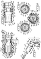
- Figs. 1-3 show a paint roller assembly generally designated 20 and shown to include a plurality of principal elements, namely, an extensible rod element generally designated 22 and supporting a rotatable roller generally designated 24 (Fig. 2), an inner telescoping tube element generally designated 26 and having positioned at its forward end a forward hand grip generally designated 28 and shown to have a preferred contour to which reference will be made later.
- Fig. 1 shows a tubular sleeve generally designated 30 and secured over an other tube generally designated 32 (Fig. 3)) over which is received a contoured large rear hand grip generally designated 34 and preferably including a grip flange 36, which keeps the handle from sliding too far down into an associated paint tray.
- An annular area 37 keeps paint form dripping or running on the O.D. of the hand grip 34 when the roller is in use, and hence the generally radially outwardly extending grip flange functions as a liquid barrier to keep paint or other coating from coming into contact with the outer surface of outer tube 32.
- this unit includes a roller mounting leg generally designated 38 positioning a pair of opposed mounting spools generally designated 30, 42 that are journalled for rotation on the roller mounting leg 38 of the rod 22 by conventional or other methods.
- the rod 22 also includes a spacer leg portion 41, an offset leg 43 and a main rod leg 44 (Fig. 1) which is extensible and retractable within the inner tube element 26 in a manner to be described.
- this unit preferably includes, as best shown in Fig. 4, a contoured front section 46 and shown to include a hexagonal arrangement of flats 47 (Fig. 9), and a slightly reduced diameter main body portion generally designated 48 having a tubular outer surface 49 and an inner surface generally designated 50, and terminating in a rear end portion generally designated 52 (Fig. 5).
- this unit is shown to include a forward end portion generally designated 54 and a main body portion 56 (Fig. 3), the outer diameter surface 58 of which positions the rear hand grip 34.
- An inner cylindrical surface 60 serves as an important part of the telescoping mechanism to be described herein.
- the forward hand grip 28 Positioned over the forward end of the inner tube element 26 is the forward hand grip generally designated 28 which is shown to include a beveled neck portion 62 providing a cylindrical sidewall 64 defining an opening through which a portion of the main rod leg 44 extends in use. A sharp scraper surface 51 is provided to prevent paint build-up on the O.D. of the rod section 44.
- the forward hand grip 28 also includes a forward sleeve portion 66 into which the contoured front section 46 of the inner tube 26 is press fit to prevent relative movement of these two elements. Flats 65 are formed in the front grip section 46; these flats match the hex-pattern sides 47 of the contoured tube section 46. Other non-circular shapes can be used, of course.
- the front hand grip 28 importantly includes a skirt-like element, here a cylindrical skirt 68, having an outer cylindrical gripping surface 70, an inwardly spaced circumferentially extending surface 72 defining a small annular passage 74 between its inner surface 72 and the outer surface 49 or the inner tube main body portion 48.
- the skirt-like element 68 has a continuous outer surface.
- the skirt and the skirt recess 74 are important features of the invention. According to the arrangement just described, the front hand grip 28 is secured in tight, movement-free relation to the front end of the inner tube 26.
- the forward end portion 54 of the outer tube 32 positions a tubular sleeve generally designated 30 that includes a neck portion 76 with a cylindrical surface 78 defining a center passage therethrough.
- the outer surface 49 of the inner tube 26 is spaced from this passage surface 78 by only a working clearance.
- a sharp edge 79 acts as a scraper for dried paint attached to the outer tube surface 49.
- An inner shoulder 77 is smaller than the O.D. of the tube 54 for purposes of retaining the parts in place.
- a lock assembly 80 which forms an important part of the invention.
- apparatus which includes three slidable telescoping members, (a rod and inner and outer tubes), two such locks are provided.
- the two locks are functionally identical, differing only in the manner in which they are secured to their associated movable elements and in their sizes.
- the locking elements slide axially relative to an associated, relatively stationary part and must be separated therefrom by a working clearance which is small enough to aid stability and alignment and large enough to permit movement when needed.
- Each locking element is carried by a relatively movable part to which it is affixed.
- a lock unit generally designated 80 includes a cylindrical main body generally designated 82.
- the lock 80 used with the rod 22 has a central, splined bore 84 for receiving a spline 86 on the rear end portion 88 of the main rod leg 44.
- the end 88 of the rod leg 44 may extend through the cylindrical opening 90 in the body 82 and the splined surface insures a snug fit between these components.
- the force available with the press-fit splined joint is much greater than that available using prior pin or stake attaching methods and thus the spline attachment is an important advantage.
- the lock assembly 80 also includes a cylindrical outer surface 92 which is non-functional relative to the association with the rod. However, this surface serves to mount the body 82 of the lock 80 relative to the tube 26.
- the lock assembly 80 includes, in addition to the body 82, a spool portion generally designated 94 and shown to include front and rear cylindrical guide surfaces 96, 98, each being defined in part by end face surfaces 100, 102 (Fig. 4) a ring stop element 104 and an inner, ring mounting cylinder 106 which is offset with respect to the center lines of the cylindrical surfaces 96, 98.
- the ring mounting cylinder generally designated 106 includes a cylindrical outer ring support surface 108. In this connection, it will be realized that while the surface 108 is circular, its center line is offset from the center lines of the circular cylindrical surfaces 96, 98. Accordingly, an eccentric groove 107 is defined between the various surfaces 100, 102, and 108.
- the other principal element of the lock assembly 80 it an eccentric split locking ring generally designated 110 and shown in Fig. 6, for example, to include an inner surface 112 for engaging the ring support surface 108, an outer, tube contracting surface 114, inner and outer locating end faces 116 and a pair of stop shoulders 118.
- the locking ring 110 is a circular cylinder on its outside diameter surface 114, and includes a circular cylindrical inner diameter surface 112, the latter however being offset from the center line of the outer diameter surface 114.
- Fig. 11 shows an analogous construction for the ring mounting cylinder 106, i.e., the inner and outer cylinders 106, 92 are both circular, but their center lines are slightly offset.
- the locking ring 110 and the ring mounting cylinder 106 may be aligned such that the outer diameter surface 114 of the ring 110 is aligned with and parallel the guide surfaces 96, 98.
- relative rotation of the ring 110 and the cylindrical locking body 82 will cause portions of the ring outer surface 114 to move radially outwardly, pinching them into engagement with the tube I.D. In operation, this is how a releasable locking action is achieved, as will now be described.
- the lock assembly 80 is inserted into the front end of the inner tube 26 with the cylindrical surfaces 96, 98 on the body 82 being in sliding contact with the inner surface 50 of the inner tube 26.
- the neck 62 of the forward hand grip 28 has a rear surface 120 facing the end face 122 of the locking body. This insures that the locking body cannot be removed from the end of the tube 26.
- a slight working clearance between the surfaces 96, 98 and the inner surface 50 of the tube 26 permits axial relative movement of these parts, as long as there is no additional interference.
- Fig. 5 shows the inner tube 26 fully extended.
- the surface 120 on the neck 76 interferes with the outermost edge portions of the outer tube 54, preventing the assembly form coming apart.
- the recess 74 will accommodate the tubular sleeve 30 on the forward end of the outer tube such that these parts may telescope into each other for full retraction.
- the skirt 68 importantly axially overlaps this sleeve 30, in effect permitting the inner tube to be gripped against rotation. Accordingly, when it is time to move the rod, a portion of the offset leg 43 may be grasped and the forward hand grip rotated slightly counterclockwise. This rotation of these parts releases the locking action.
- the rod When the desired position of extension or retraction is reached, the rod is held at the offset leg and the forward hand grip 28 manipulated clockwise as just described.
- the front and rear hand grips are grasped, and relative rotation, first counterclockwise and then clockwise will respectively release and retighten the slidable elements relative to each other.
- While one form of the invention is embodied in an arrangement having three movable elements and two locking units, additional telescoping members may be added simply by telescoping then in the same manner as the present elements are telescoped.
- a major advantage of the invention is that the forward hand grip does not restrict telescoping movement of the outer tube relative to the inner tube, but still provides a surface that can be grasped when the rod is fully retracted and the outer tube surrounds the inner tube. In prior art constructions, this was difficult or impossible to be done with the hands because the action of telescoping the parts together prevented access to the relatively rotatable parts that were required to be gripped.
- an eccentric-ring-in-an-eccentric-groove-type locking mechanism has been described. This is the preferred form of locking apparatus from the standpoint of simplicity, reliability, ease of use and low cost.
- other one-way locking devices are known which may also be suitable for practicing the invention. These include overrunning clutch assemblies, generally including those using spring biased rollers movable in inclined ramps, and tilting-type sprag assemblies such as those used on pipe clamps, etc.
- the tubing and aluminum or steel for the rod section are used for the tubing and aluminum or steel for the rod section, with the locking device parts being made from appropriate plastic material such as nylon or the like.
- the front hand grip is preferably injection molded from a relatively rigid plastic material, whereas the main or remote handle grip is preferably made from or covered with a foam plastic or rubber.
- the ring and skirt 36 and the annular anti-drip groove 37 are important commercial aspects of the invention and are an improvement over roller handles that used hooks or the like to prevent the roller form sliding into the tray. These devices required alignment of the hook or other stop member with the tray. Since the present handle rotates relative to the rod and the roller to adjust the length, the provision of a continuous skirt or ring rather than a hook or the like is strongly preferred so that an engagement surface for the paint tray is always provided.
Landscapes
- Engineering & Computer Science (AREA)
- Mechanical Engineering (AREA)
- Coating Apparatus (AREA)
- Mutual Connection Of Rods And Tubes (AREA)
Applications Claiming Priority (2)
| Application Number | Priority Date | Filing Date | Title |
|---|---|---|---|
| US278838 | 1994-07-22 | ||
| US08/278,838 US5502864A (en) | 1993-02-25 | 1994-07-22 | Paint applicator with improved extensible handle |
Publications (2)
| Publication Number | Publication Date |
|---|---|
| EP0693322A2 true EP0693322A2 (de) | 1996-01-24 |
| EP0693322A3 EP0693322A3 (de) | 1996-05-29 |
Family
ID=23066594
Family Applications (1)
| Application Number | Title | Priority Date | Filing Date |
|---|---|---|---|
| EP95302291A Withdrawn EP0693322A3 (de) | 1994-07-22 | 1995-04-06 | Farbauftragegerät mit ausziebarem Handgriff |
Country Status (5)
| Country | Link |
|---|---|
| US (2) | US5502864A (de) |
| EP (1) | EP0693322A3 (de) |
| JP (1) | JP2952565B2 (de) |
| AU (1) | AU683989B2 (de) |
| CA (1) | CA2145710C (de) |
Cited By (5)
| Publication number | Priority date | Publication date | Assignee | Title |
|---|---|---|---|---|
| GB2329328A (en) * | 1997-09-17 | 1999-03-24 | Universal International Plc | Paint brush |
| GB2441055A (en) * | 2006-08-19 | 2008-02-20 | Harris L G & Co Ltd | A paint roller handle |
| WO2009039578A1 (en) * | 2007-09-28 | 2009-04-02 | Walter Peter Wright | Improved internal locking device for extendable telescoping poles |
| US8627549B2 (en) | 2010-09-09 | 2014-01-14 | John Vernieu | Grip application device for applying a grip to a handle |
| CN106041842A (zh) * | 2016-08-08 | 2016-10-26 | 苏州亘富机械科技有限公司 | 一种可调手柄 |
Families Citing this family (66)
| Publication number | Priority date | Publication date | Assignee | Title |
|---|---|---|---|---|
| IT239017Y1 (it) * | 1995-10-31 | 2001-02-19 | Vebe Snc Di Patelli Giuseppe & | Dispositivo attivato e mantenuto da pressione assiale per reciprocobloccaggio di spezzoni di tubo telescopico particolarmente a |
| US5743577A (en) * | 1996-07-19 | 1998-04-28 | Robert D. Newman, Sr. | Extension handle apparatus |
| US5857241A (en) * | 1997-02-19 | 1999-01-12 | The Wooster Brush Company | Soft grip handle |
| US5921196A (en) * | 1997-05-07 | 1999-07-13 | Stephen O. Slatter | Sport fishing outrigger apparatus |
| EP1004263A1 (de) * | 1998-11-09 | 2000-05-31 | The Procter & Gamble Company | Teleskopischer Sprüharm |
| US20030019180A1 (en) * | 1999-11-09 | 2003-01-30 | Warren Peter A. | Foldable member |
| US8074324B2 (en) * | 1999-11-09 | 2011-12-13 | Foster-Miller, Inc. | Flexible, deployment rate damped hinge |
| US6374565B1 (en) * | 1999-11-09 | 2002-04-23 | Foster-Miller, Inc. | Foldable member |
| US6349451B1 (en) * | 2000-01-28 | 2002-02-26 | Robert D. Newman/Specialty Products Of Greenwood, Missouri, Inc. | Universal tool handle configured for various extension pole connectors |
| US6671930B2 (en) * | 2000-02-01 | 2004-01-06 | Donald D. Lanz | Adjustable tool mount apparatus and specialized tool handle thereof |
| CA2342462A1 (en) | 2000-03-30 | 2001-09-30 | Newell Operating Company | Paint roller and extension pole |
| US20030015057A1 (en) * | 2001-07-23 | 2003-01-23 | Spx Corporation | Extensible jack handle |
| US20040100109A1 (en) * | 2002-11-25 | 2004-05-27 | Johnson Richard Del | Extendable, non-rotating reacher |
| US7096530B2 (en) * | 2003-09-09 | 2006-08-29 | Newell Operating Company | Paint roller with extendable handle |
| EP1694267A2 (de) * | 2003-12-17 | 2006-08-30 | DAVIS, David T. | Pneumatischer lift |
| MXPA06012795A (es) * | 2004-05-05 | 2007-02-15 | Rubbermaid Commercial Products | Almohadillas de trapeador codificadas por color y metodo para codificar por color las mismas. |
| WO2005107565A1 (en) * | 2004-05-05 | 2005-11-17 | Rubbermaid Commercial Products Llc | Color coded mop pads and method of color coding same |
| US20060016054A1 (en) * | 2004-07-20 | 2006-01-26 | Muzzillo Sean A | Light duty consumable prosthesis |
| US20080257279A1 (en) * | 2004-07-28 | 2008-10-23 | Judith Yvonne Jezl | Device for handling reptiles |
| USD529294S1 (en) | 2005-01-31 | 2006-10-03 | Rubbermaid Commercial Products Llc | Universal joint |
| USD549414S1 (en) | 2005-01-31 | 2007-08-21 | Rubbermaid Commercial Products Llc | Mop frame |
| USD533356S1 (en) | 2005-01-31 | 2006-12-12 | Rubbermaid Commercial Products Llc | Universal joint |
| US20060218752A1 (en) * | 2005-03-30 | 2006-10-05 | Potempa Michael M | Collet locks and extension pole assemblies comprising same |
| US20060230581A1 (en) * | 2005-04-15 | 2006-10-19 | Specialty Products Of Greenwood, Missouri, Inc. | Locking mechanism for an extension pole |
| USD548913S1 (en) | 2005-05-10 | 2007-08-14 | Rubbermaid Commercial Products Llc | Mop bucket and wringer |
| USD547017S1 (en) | 2005-05-10 | 2007-07-17 | Rubbermaid Commercial Products Llc | Mop handle |
| USD528729S1 (en) | 2005-05-10 | 2006-09-19 | Rubbermaid Commerical Products Llc | Cart |
| US20060282988A1 (en) * | 2005-06-21 | 2006-12-21 | Thomas Lin | Control structure of retractable handle |
| US20070163065A1 (en) * | 2006-01-19 | 2007-07-19 | Chang Jia L | Extendible cleaner rod |
| US7281292B1 (en) * | 2006-02-16 | 2007-10-16 | Felix John J | Combination paint roller frame and scraper |
| US7780210B1 (en) * | 2006-03-02 | 2010-08-24 | Boyum Paul H | Pickup box retrieval implement |
| USD578769S1 (en) | 2006-07-17 | 2008-10-21 | Kester Patterson | Adjustable paint roller |
| USD563751S1 (en) * | 2006-08-18 | 2008-03-11 | Lanz Donald D | Socket mount, angle adjustable tool holder for extension poles |
| US7490880B1 (en) | 2006-12-06 | 2009-02-17 | Matsui Jason M | Tool and method of use |
| USD549912S1 (en) | 2007-01-12 | 2007-08-28 | Rubbermaid Commercial Products Llc | Mop |
| US7673910B2 (en) | 2007-06-10 | 2010-03-09 | James Moon | Extendable fluid transport apparatus |
| US7670305B2 (en) * | 2007-11-13 | 2010-03-02 | Sam Zhadanov | Device for showering and turbo-rotative water treatment |
| US20090184207A1 (en) * | 2008-01-22 | 2009-07-23 | Warren Peter A | Synchronously self deploying boom |
| US8341798B2 (en) * | 2008-12-08 | 2013-01-01 | The Wooster Brush Company | Expandable supports for paint roller covers |
| USD615261S1 (en) | 2009-02-12 | 2010-05-04 | American Safety Razor | Scraper |
| USD615262S1 (en) | 2009-02-24 | 2010-05-04 | American Safety Razor | Scraper |
| US20120319419A1 (en) * | 2010-12-22 | 2012-12-20 | Golestani Iraj H | Tool attachment device for elongated handles |
| USD660535S1 (en) * | 2011-05-13 | 2012-05-22 | Menius Marvin L | Cleaning device |
| USD667598S1 (en) * | 2011-10-19 | 2012-09-18 | Menius Marvin L | Cleaning device |
| US9156571B2 (en) | 2011-10-28 | 2015-10-13 | Restore Medical Solutions, Inc. | Adjustable surgical instrument stringer with pegs, tray system, and method of sterilization |
| US9259272B2 (en) | 2011-10-28 | 2016-02-16 | Restore Medical Solutions, Inc. | Adjustable surgical instrument stringer, tray system, and method of sterilization |
| USD665960S1 (en) * | 2011-12-05 | 2012-08-21 | Menius Marvin L | Cleaning device |
| TWM434658U (en) * | 2012-03-03 | 2012-08-01 | Jin-Tan Huang | Structure for retractable rod with alignment function |
| US9009920B1 (en) * | 2012-08-02 | 2015-04-21 | Mark J. Ramsey | Motorized extension pole |
| US8800113B1 (en) * | 2013-03-15 | 2014-08-12 | Blackstone Medical, Inc. | Rigid modular connector |
| US9102051B2 (en) * | 2013-07-19 | 2015-08-11 | Chia-Yu Chen | Retractable rod structure of hand tool |
| US9168563B1 (en) | 2014-05-30 | 2015-10-27 | James A. Kalmon | Paint roller frame with a barbed cage |
| FR3026400B1 (fr) * | 2014-09-26 | 2016-10-07 | Exel Ind | <p>dispositif pour le transfert d’un liquide depuis un bidon jusqu’a une cuve de facon etanche</p> |
| US10624447B1 (en) * | 2016-09-22 | 2020-04-21 | Crown Down Cleaners, Llc | Power driven duster and cleaner apparatus |
| US10363773B2 (en) * | 2017-05-05 | 2019-07-30 | Troy Pippus | Accessory holder for a paint tray carrier |
| US20180368384A1 (en) * | 2017-06-21 | 2018-12-27 | Esther Kim | Extendable and Adjustable Insect Entrapment Apparatus |
| US10315304B1 (en) * | 2018-10-03 | 2019-06-11 | Keith Cowan | Cargo retrieval assembly |
| US11698092B2 (en) | 2020-06-22 | 2023-07-11 | Unger Marketing International | Telescopic pole for a cleaning implement |
| USD1028169S1 (en) | 2020-10-29 | 2024-05-21 | Unger Marketing International, Llc | Water conditioning system |
| USD981222S1 (en) | 2021-01-18 | 2023-03-21 | Unger Marketing International, Llc | Clamp for an extendable pole |
| USD973989S1 (en) | 2021-01-18 | 2022-12-27 | Unger Marketing International, Llc | Extendable window cleaning tool |
| USD976506S1 (en) | 2021-01-20 | 2023-01-24 | Unger Marketing International, Llc | Pole connection for a window cleaning tool |
| USD1007793S1 (en) | 2021-01-20 | 2023-12-12 | Unger Marketing International, Llc | Pole connection for a window cleaning tool |
| USD1008582S1 (en) | 2021-01-20 | 2023-12-19 | Unger Marketing International, Llc | Pole connection for a window cleaning tool |
| CN114223379B (zh) * | 2021-12-15 | 2023-01-31 | 格力博(江苏)股份有限公司 | 一种悬挂装置及割草机 |
| WO2025019230A1 (en) * | 2023-07-14 | 2025-01-23 | Two Seventy Six Llc | Extendable dual handle shaft |
Family Cites Families (15)
| Publication number | Priority date | Publication date | Assignee | Title |
|---|---|---|---|---|
| US1327597A (en) * | 1919-03-24 | 1920-01-06 | Richard T Greene | Brush-handle |
| US3407424A (en) * | 1965-09-28 | 1968-10-29 | Otto R. Lanzarone | Adjustable, extensible, telescopic and collapsible handle for attachment to household cleaning devices |
| US3380097A (en) * | 1967-07-24 | 1968-04-30 | Painter Corp E Z | Extension handle for paint roller |
| US3596946A (en) * | 1970-03-09 | 1971-08-03 | Wooster Brush Co The | Cam lock for telescopic members |
| US3751748A (en) * | 1971-12-15 | 1973-08-14 | Wooster Beush Co | Hand held roller frame |
| US3879140A (en) * | 1973-01-11 | 1975-04-22 | Erwin A Ritter | Painting apparatus |
| US3866257A (en) * | 1973-12-26 | 1975-02-18 | Sr William H Cansdale | Swivel top paint roller with adjustable handle |
| US4325157A (en) * | 1979-08-09 | 1982-04-20 | E Z Painter Corporation | Extension handle |
| JPS5712270U (de) * | 1980-06-20 | 1982-01-22 | ||
| US4466152A (en) * | 1982-05-03 | 1984-08-21 | Seco Industries, Inc. | Bowl mop |
| JPS602807Y2 (ja) * | 1982-08-17 | 1985-01-26 | 武 中岡 | 伸縮脚 |
| US4659135A (en) * | 1984-01-20 | 1987-04-21 | Schmelzer Corporation | Adjustable arm rest |
| US4653142A (en) * | 1984-09-19 | 1987-03-31 | Reach High Products, Inc. | Extensible tool handle |
| US4659125A (en) * | 1985-05-23 | 1987-04-21 | Ching Chuan | Handle rod structure of golf retriever |
| US5099539A (en) * | 1990-12-06 | 1992-03-31 | Forester Glen R | Telescoping extension rod having pivotably adjustable tool head |
-
1994
- 1994-07-22 US US08/278,838 patent/US5502864A/en not_active Expired - Lifetime
-
1995
- 1995-03-28 CA CA002145710A patent/CA2145710C/en not_active Expired - Fee Related
- 1995-04-06 EP EP95302291A patent/EP0693322A3/de not_active Withdrawn
- 1995-04-13 US US08/421,622 patent/US5598598A/en not_active Expired - Lifetime
- 1995-04-18 AU AU16505/95A patent/AU683989B2/en not_active Ceased
- 1995-07-21 JP JP7207800A patent/JP2952565B2/ja not_active Expired - Fee Related
Cited By (6)
| Publication number | Priority date | Publication date | Assignee | Title |
|---|---|---|---|---|
| GB2329328A (en) * | 1997-09-17 | 1999-03-24 | Universal International Plc | Paint brush |
| GB2441055A (en) * | 2006-08-19 | 2008-02-20 | Harris L G & Co Ltd | A paint roller handle |
| GB2441055B (en) * | 2006-08-19 | 2011-01-05 | Harris L G & Co Ltd | A paint roller handle |
| WO2009039578A1 (en) * | 2007-09-28 | 2009-04-02 | Walter Peter Wright | Improved internal locking device for extendable telescoping poles |
| US8627549B2 (en) | 2010-09-09 | 2014-01-14 | John Vernieu | Grip application device for applying a grip to a handle |
| CN106041842A (zh) * | 2016-08-08 | 2016-10-26 | 苏州亘富机械科技有限公司 | 一种可调手柄 |
Also Published As
| Publication number | Publication date |
|---|---|
| CA2145710C (en) | 2000-09-26 |
| JPH09105405A (ja) | 1997-04-22 |
| US5598598A (en) | 1997-02-04 |
| CA2145710A1 (en) | 1996-01-23 |
| JP2952565B2 (ja) | 1999-09-27 |
| AU683989B2 (en) | 1997-11-27 |
| US5502864A (en) | 1996-04-02 |
| EP0693322A3 (de) | 1996-05-29 |
| AU1650595A (en) | 1996-02-01 |
Similar Documents
| Publication | Publication Date | Title |
|---|---|---|
| US5598598A (en) | Paint applicator with improved extensible handle | |
| US5460458A (en) | Tool reach extension apparatus | |
| US4524484A (en) | Extension handle having cooperating male and female locking sleeves | |
| US5692856A (en) | Lock assembly for extension handle | |
| US5011319A (en) | Locking mechanism for telescoping tubular poles | |
| US7096530B2 (en) | Paint roller with extendable handle | |
| CA2209147C (en) | Multi-faceted extension pole | |
| US6311368B1 (en) | Handle for household utensils | |
| US7302745B2 (en) | Method for locking a first tube member to a second tube member | |
| US8240008B2 (en) | On-the-go adjustable extension pole providing hands-free tool connection and disconnection | |
| WO1995002140A1 (en) | Flow-through telescoping pole | |
| NZ528087A (en) | Wand assembly for domestic applicance | |
| US6874557B2 (en) | Ergonomic and easily serviceable taper tool | |
| JP2003529010A (ja) | カートリッジから物質を分与するデバイス | |
| EP1138398A2 (de) | Unterarmgestützter Farbroller | |
| US7314074B2 (en) | Ergonomic and easily serviceable taper tool | |
| EP3601128B1 (de) | Wickelvorrichtung zum wickeln eines flexiblen elements davon | |
| US5690181A (en) | Tool handle mounting structure for garden tools | |
| US12263501B2 (en) | Compound applicator | |
| EP1730408B1 (de) | Anordnung zur einstellung von teleskopisch bewegbaren elementen | |
| GB2282435A (en) | Baton | |
| US20240336207A1 (en) | Load carriers and add-on parts for load carriers | |
| AU2003252873B2 (en) | Wand assembly for a domestic appliance |
Legal Events
| Date | Code | Title | Description |
|---|---|---|---|
| PUAI | Public reference made under article 153(3) epc to a published international application that has entered the european phase |
Free format text: ORIGINAL CODE: 0009012 |
|
| AK | Designated contracting states |
Kind code of ref document: A2 Designated state(s): DE ES FR GB IT |
|
| PUAL | Search report despatched |
Free format text: ORIGINAL CODE: 0009013 |
|
| AK | Designated contracting states |
Kind code of ref document: A3 Designated state(s): DE ES FR GB IT |
|
| STAA | Information on the status of an ep patent application or granted ep patent |
Free format text: STATUS: THE APPLICATION HAS BEEN WITHDRAWN |
|
| 17P | Request for examination filed |
Effective date: 19961018 |
|
| 18W | Application withdrawn |
Withdrawal date: 19961115 |